MIXING CONSOLES
USER’S MANUAL
MANUALE D’USO
ENGLISH
ITALIANO

2
96MAN0174-REV.43/22
IMPORTANT SAFETY INSTRUCTIONS
Watch for these symbols:
• The lightning flash with arrowhead symbol within an equilateral triangle is intended to alert the user to
the presence of uninsulated “dangerous voltage” within the product’s enclosure, that may be of sufficient
magnitude to constitute a risk of electric shock to persons.
• The exclamation point within an equilateral triangle is intended to alert the user to the presence of
important operating and maintenance (servicing) instructions in the literature accompanying the
appliance.
1. Read these instructions.
2. Keep these instructions.
3. Heed all warnings.
4. Follow all instructions.
5. Do not use this apparatus near water.
6. Clean only with dry cloth.
7. Do not block any ventilation openings. Install in accordance with the manufacturer’s instructions.
8. Do not install near any heat sources such as radiators, heat registers, stoves, or other apparatus (including
amplifiers) that produce heat.
9. Do not defeat the safety purpose of the polarized or grounding-type plug. A polarized plug has two blades
with one wider than the other. A grounding-type plug has two blades and a third grounding prong. The
wide blade or the third prong are provided for your safety. If the provided plug does not fit into your
outlet, consult an electrician for replacement of the obsolete outlet.
10. Protect the power cord from being walked on or pinched, particularly at plugs, convenience receptacles,
and the point where they exit from the apparatus.
11. Only use attachments/accessories specified by the manufacturer.
12. Use only with the cart, stand, tripod, bracket, or table specified by the manufacturer, or sold with the
apparatus. When a cart is used, use caution when moving the cart/apparatus combination to avoid injury
from tip-over.
13. Unplug this apparatus during lightning storms or when unused for long periods of time.
14. Refer all servicing to qualified service personnel. Servicing is required when the apparatus has been
damaged in any way, such as power supply cord or plug is damaged, liquid has been spilled or objects have
fallen into the apparatus, the apparatus has been exposed to rain or moisture, does not operate normally,
or has been dropped.
15. Warning: to reduce the risk of fire or electric shock, do not expose this apparatus to rain or moisture.
16. Do not expose this equipment to dripping or splashing and ensure that no objects filled with liquids, such
as vases, are placed on the equipment.
17. To completely disconnect this apparatus from the ac mains, disconnect the AC ADAPTER unit plug from the
AC receptacle.
18. The mains plug of the power supply cord shall remain readily operable.
19. This apparatus contains potentially lethal voltages. To prevent electric shock or hazard, do not remove the
chassis, input module or ac input covers. No user serviceable parts inside. Refer servicing to qualified
service personnel.
20. The equipment covered by this manual are not intended for high moisture outdoor environments.
Moisture can damage the internal electronic and cause corrosion of electrical contacts and metal parts.
Avoid exposing the equipment to direct moisture.
21. Use only the AC/DC ADAPTER provided with the unit to connect the console to the mains.
22. Use only the USB type A – type A cable provided with the unit to connect the AC ADAPTER with the
console.
23. The AC/DC ADAPTER complies with all applicable safety standard.
24. No serviceable parts are inside the AC/DC ADAPTER, in case of fault replace it with a new one.

3
This marking shown on the product or its literature, indicates that it should not be disposed with other
household wastes at the end of its working life. To prevent possible harm to the environment or human health
from uncontrolled waste disposal, please separate this from other types of wastes and recycle it responsibly to
promote the sustainable reuse of material resources. Household users should contact either the retailer where
they purchased this product, or their local government office, for details of where and how they can take this
item for environmentally safe recycling. Business users should contact their supplier and check the terms and
conditions of the purchase contract. This product should not be mixed with other commercial wastes for
disposal.
FEDERAL COMMUNICATIONS COMMISSION (FCC) STATEMENT
This device complies with part 15 of the FCC rules. Operation is subject to the following two conditions:
(1) This device may not cause harmful interference, and
(2) this device must accept any interference received, including interference that may cause undesired operation.
CAUTION: Changes or modifications not expressly approved by the party responsible for compliance could void the user’s authority
to operate the equipment.
NOTE: This equipment has been tested and found to comply with the limits for a Class B digital device, pursuant to part 15 of the
FCC Rules. These limits are designed to provide reasonable protection against harmful interference in a residential installation. This
equipment generates, uses, and can radiate radio frequency energy and, if not installed and used in accordance with the instruction
manual, may cause harmful interference to radio communications. However, there is no guarantee that interference will not occur in
a particular installation. If this equipment does cause harmful interference to radio or television reception, which can be determined
by turning the equipment off and on, the user is encouraged to try to correct the interference by one or more of the following
measures:
• Reorient or relocate the receiving antenna.
• Increase the separation between the equipment and receiver.
• Connect the equipment into an outlet on a circuit different from that to which the receiver is connected.
• Consult the dealer or an experienced radio/TV technician for help.
DECLARATION OF CONFORMITY
The product is in compliance with the following European Directives:
EMC 2014/30/EU, RED 2014/53/EU, LVD 2014/35/EU, RoHS 2011/65/EU and WEEE 2012/19/EU.
WARNING (EN 55032 CISPR 32)
Under the EM disturbance, the ratio of signal-noise will be changed above 10 dB.
LIMITED WARRANTY
Proel warrants all materials, workmanship and proper operation of this product for a period of two years from the original date of
purchase. If any defects are found in the materials or workmanship or if the product fails to function properly during the applicable
warranty period, the owner should inform about these defects the dealer or the distributor, providing receipt or invoice of date of
purchase and defect detailed description. This warranty does not extend to damage resulting from improper installation, misuse,
neglect or abuse. Proel S.p.A. will verify damage on returned units, and when the unit has been properly used and warranty is still
valid, then the unit will be replaced or repaired. Proel S.p.A. is not responsible for any “direct damage” or “indirect damage” caused
by product defectiveness.
• This unit package has been submitted to ISTA 1A integrity tests. We suggest you control the unit conditions immediately after
unpacking it.
• If any damage is found, immediately advise the dealer. Keep all unit packaging parts to allow inspection.
• Proel is not responsible for any damage that occurs during shipment.
• Products are sold “delivered ex warehouse” and shipment is at charge and risk of the buyer.
• Possible damages to unit should be immediately notified to forwarder. Each complaint for package tampered with should be
done within eight days from product receipt.
CONDITIONS OF USE
Proel do not accept any liability for damage caused to third parties due to improper installation, use of non-original spare parts, lack
of maintenance, tampering or improper use of this product, including disregard of acceptable and applicable safety standards. Proel
strongly recommends that this loudspeaker cabinet be suspended taking into consideration all current National, Federal, State and
Local regulations. The product must be installed be qualified personal. Please contact the manufacturer for further information.

4
SUMMARY - ENGLISH
INTRODUCTION ................................................................................................................................... 5
DESCRIPTION ....................................................................................................................................... 5
INSTRUCTIONS .................................................................................................................................... 5
1. MIC/LINE XLR input .................................................................................................................. 5
2. MIC/LINE JACK input ................................................................................................................ 5
3. LINE/-30dB switch .................................................................................................................... 5
4. +48V phantom switch .............................................................................................................. 7
5. +48V LED .................................................................................................................................. 7
6. PEAK detector .......................................................................................................................... 7
7. GAIN control ............................................................................................................................. 7
8. LOW CUT switch ....................................................................................................................... 7
9. HIGH control ............................................................................................................................. 7
10. MID control ........................................................................................................................... 7
11. FREQ control ......................................................................................................................... 7
12. LOW control .......................................................................................................................... 7
13. FX/AUX send control ............................................................................................................. 7
14. PAN control ........................................................................................................................... 8
15. MONO CHANNEL FADER LEVEL control ................................................................................. 8
16. LINE (L MONO – R) jack inputs .............................................................................................. 8
17. STEREO IN MINI JACK input .................................................................................................. 8
18. BAL control ........................................................................................................................... 8
19. STEREO CHANNEL LEVEL control ........................................................................................... 8
20. FX/AUX send control ............................................................................................................. 8
21. AUX SEND jack output .......................................................................................................... 8
22. FX PRESETS selector .............................................................................................................. 8
23. FX DISPLAY number ............................................................................................................... 8
24. FX LEVEL control ................................................................................................................... 9
25. MP3 PLAYER/RECORDER ....................................................................................................... 9
26. USB PORT .............................................................................................................................. 9
27. CH / USB BT switch ............................................................................................................... 9
28. MAIN MIX FADER control ...................................................................................................... 9
29. MAIN MIX L & R XLR output .................................................................................................. 9
30. PHONES and C.ROOM level control .................................................................................... 10
31. PHONES stereo jack output ................................................................................................ 10
32. C.ROOM jack output ........................................................................................................... 10
33. L & R LEVEL meters ............................................................................................................. 10
34. ON LED ................................................................................................................................ 10
35. POWER switch .................................................................................................................... 10
36. DC IN 5V 1A supply socket input ......................................................................................... 10
DSP EFFECTS PROCESSOR OPERATING INSTRUCTIONS ...................................................................... 11
MP3 PLAYER/RECORDER OPERATING INSTRUCTIONS ....................................................................... 11
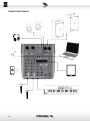
CONNECTION EXAMPLE .................................................................................................................... 14
TECHNICAL SPECIFICATION ................................................................................................................ 15
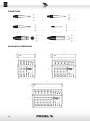
CONNECTORS .................................................................................................................................... 16
MECHANICAL DIMENSIONS ............................................................................................................... 16

5
INTRODUCTION
Thank you for choosing this PROEL product and for your trust in our brand, synonymous of accuracy, high quality
and reliability. All our products are CE approved and designed for continuous use in professional applications.
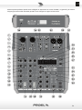
DESCRIPTION
PLAYMIX is a series of mixers created by PROEL to offer in a very compact and stylish package a high inputs
density, a full set of features and a superior audio quality, at a very convenient price point.
PLAYMIX mixers are available in 3 models, with the same channel and master functions, but offering 6, 8 or 10
inputs respectively. The mono MIC/LINE channels feature low-noise, high-headroom microphone preamps, 3-
band EQ with sweep MIDs and HPF, and 60mm control faders, for a full control of your sound.
All models feature an advanced DIGITAL section with LCD display, including:
- A high-quality 24-bit built-in DSP with 100 studio-grade presets of single and combined effect
(REVERBS, DELAYS, MODULATIONS)
- A 48KHz stereo USB audio interface for playing/recording thru PC connection
- A built-in MP3 player from USB memory key or BLUETOOTH interface
- On-the-go stereo recording on USB memory key
Carefully designed and engineered in Italy by PROEL, PLAYMIX mixers are hosted in rugged cases, providing
extended durability for a stage-proof use and they offer in an ultra-compact format the performance of
professional consoles, delivering a clean and accurate sound for a wide range of applications.
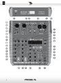
INSTRUCTIONS
NOTE: the three models differ only by the number of MONO channels, 2, 4 and 6 respectively. The
STEREO channels (2) and the MASTER section are the same for all the three models. The following
instructions refer to the channel numbering of PLAYMIX6.
1. MIC/LINE XLR input
This is a female XLR connector that accepts a balanced input from microphones, instruments or line audio
devices. The XLR input is wired as follows:
Pin 1 = shield or ground
Pin 2 = + positive or "hot"
Pin 3 = - negative or "cold"
2. MIC/LINE JACK input
This is a female JACK connector that accepts a balanced input from microphones, instruments or line audio
devices. The JACK input is wired as follows:
Tip = + positive or "hot"
Ring = - negative or "cold"
Sleeve = shield or ground
When connecting an unbalanced signal, wire them as follows:
Tip = + positive or "hot"
Sleeve = shield or ground
3. LINE/-30dB switch
Pressing this button, a 30dB attenuation is engaged on both XLR and JACK inputs. Use this button when
connecting a LINE output device or, in general, to avoid the clipping (PEAK LED flashing) when a high-level
signal is connected.

6

7
4. +48V phantom switch
This switch engages the phantom power on MIC Input. Most professional condenser microphones and active
DIBOX require phantom power, which is a lower DC voltage delivered to the microphone on pin 2 and 3 of
the XLR microphone connector. Dynamic microphones do not require phantom power, however phantom
power will not harm most dynamic microphones should you plug one in while the phantom power is on.
Check the manual of your microphone to find out for sure whether or not phantom power can damage it.
5. +48V LED
This LED shows if the phantom power is on or off for the correspondent channel XLR input.
6. PEAK detector
The PEAK LED indicates that the input signal is near to the CLIPPING point.
IMPORTANT: if the LED PEAK flashes, reduce the level of the input signal using the GAIN control and/or the
PAD switch.
7. GAIN control
The gain control adjusts the input sensitivity of the mic and line inputs. This allows the signal from mics and
instruments to be adjusted to optimal internal levels.
8. LOW CUT switch
This switch cuts low frequencies below 80 Hz at a rate of 6 dB per octave. We recommend that you use the LOW
CUT filter on all connected microphones except those for kick drum, bass guitar, bassy synth patches or recordings.
These aside, there isn’t much that you want to hear below 80 Hz and filtering it out makes the low frequency you
want much punchier and more defined. The LOW CUT filter can also help to reduce the possibility of feedbacks in
live situations, and it helps to conserve the amplifier power. Another way to use the LOW CUT filter is in
combination with the LOW EQ on vocals during live performances. Many times, bass shelving EQ can really benefit
voices, but adding LOW EQ also boosts stage rumble, mic handling clunks, and breath pops.
9. HIGH control
This control gives you up to 15dB boost or cut at 12KHz with a “SHELVING” curve shape. Use it to increase or
reduce the sound “clarity” or “brightness”.
10. MID control
This control gives you up to 12 dB boost or cut at the frequency determined by the FREQ knob (see FREQ
next) with a "PEAKING" curve shape. Use it to add or reduce the sound "presence".
11. FREQ control
This knob ranges from 250 Hz to 6 kHz and determines the center frequency for the MID EQ. This allows you
to select the precise narrow band of frequencies you want to be affected by the MID EQ.
12. LOW control
This control gives you up to 15dB boost or cut at 80Hz with a “SHELVING” curve shape. Use it to increase or
reduce the sound “punch”.
13. FX/AUX send control
This control sends the signal to the internal Digital Multieffect processor and to the AUX SEND output. This
signal is post-fader or, in other words, it depends on the position of the channel's FADER.

8
14. PAN control
It adjusts the amount of channel signal sent to the left versus the right outputs. Use it to position the sound
origin in a panoramic stereo scene.
15. MONO CHANNEL FADER LEVEL control
It adjusts the level of the channel signal and send it to the MAIN MIX outputs.
16. LINE (L MONO – R) jack inputs
These are female JACK connectors that accepts a balanced or unbalanced line level input signal from almost
any line source. If the R jack is not inserted, the L channel operates as a MONO channel with this input as a
single signal source. Wiring is the same of previous paragraphs.
17. STEREO IN MINI JACK input
This is a MINI JACK (3.5mm) female connector that accepts a STEREO MINI JACK plug from Computer / Tablet
/ Cell phone / MP3 players. The MINI JACK is wired as follows:
Tip = positive signal of left channel
Ring = positive signal of right channel
Sleeve = shield or ground
This input is wired in parallel to the input of the first stereo channel (3/4 of PLAYMIX6, 5/6 of PLAYMIX8, 7/8
of PLAYMIX10): both inputs can be listened simultaneously, but we recommend using only one of the two at
a time.
18. BAL control
It adjusts the amount of channel signal sent to the left versus the right outputs if the channel is used as
MONO, or it fades the LEFT or RIGHT signal amount if the channel is used as STEREO.
19. STEREO CHANNEL LEVEL control
It adjusts the level of the STEREO channel signal and send it to the MAIN MIX outputs.
20. FX/AUX send control
This control sends the signal to the internal Digital Multieffect processor and to the AUX SEND output. This
signal is post-level control and is the sum of both L&R channels.
21. AUX SEND jack output
This jack connector sends out unbalanced line-level signals made of the sum of the input channel’s FX sends,
usually for connecting to an external effect device or a stage monitor. This signal is post-fader or, in other
words, it depends on the position of the channel’s FADER.
22. FX PRESETS selector
Rotating this knob is possible to select the DSP effects.
23. FX DISPLAY number
This display shows the number of the currently loaded preset. When rotating the FX PRESETS selector, the
display scrolls the numbers and flashes until the new preset is confirmed by pressing the knob.

9
24. FX LEVEL control
It adjusts the level of the internal effect signal sent to the MAIN MIX outputs.
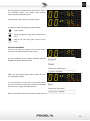
25. MP3 PLAYER/RECORDER
This is the MP3 PLAYER/RECORDER section. The display shows the player’s current status and the buttons
below allow to control it. The player can operate with a USB PENDRIVE or with a COMPUTER or as
BLUETOOTH player. See further in this manual the operating instructions for the MP3 PLAYER/RECORDER.
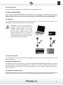
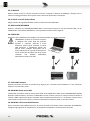
26. USB PORT
This is the USB port to which you can connect a USB pendrive or a PC. For the connection to a PC use the
same USB-A / USB-A cable provided with the power adapter.
IMPORTANT: when a personal computer is
connected to the front panel USB port, the
computer supplies power to the mixer
through this port. Therefore, the
rear USB
port and AC/DC adapter should not be
connected. M
ake sure the PC USB port is
capable of powering the mixer, because it
may happen that some old computers do not
have enough power on the USB port.
27. CH / USB BT switch
This switch allows to select the inputs for second STEREO channel between its physical JACK connectors and
the BT / MP3 player.
28. MAIN MIX FADER control
The MAIN MIX controls the output level just before the MAIN MIX and HEADPHONE/C.ROOM outputs. When
the potentiometer is fully down the MAIN MIX is off, while the "0" indicates a +4dBu nominal output level.
Typically, this control is set near the "0" label and left alone, but it can be used for song fadeouts or quick
system-wide mutes.
29. MAIN MIX L & R XLR output
These XLR and provide a line-level signal that represents the fully mixed stereo signal controlled by the MAIN
MIX. Connect these to the inputs of your power amplifier, powered speaker or other audio processors.

10
30. PHONES and C.ROOM level control
This controls the PHONES and C.ROOM output's level.
31. PHONES stereo jack output
STEREO JACK connector for the headphones output. The signal is the same of MAIN MIX outputs.
32. C.ROOM jack output
These JACK connectors provide a line-level signal that can be used to monitor the MAIN MIX program or as
an additional output.
33. L & R LEVEL meters
The level meters are made of two columns of four LEDs with three colors to indicate different ranges of signal
level:
• green = shows the nominal operative level of the signal (from -10 to 0 dB)
• yellow = shows the max operative level of the signal (+3 dB)
• red = shows an excessive signal level (+6dB).
NOTICE: For correct use, the RED LEDs must always remain OFF except for occasional short
periods.
34. ON LED
Indicates when the mixer is switched on.
35. POWER switch
Switch this one on and your mixer has power. Switch it off and it doesn’t. Make sure that all master output
knobs are turned all the way down when powering your mixer up or down.
36. DC IN 5V 2A supply socket input
Here’s where you plug in your mixer’s external power supply. You should always connect your power supply
to the mixer before you plug the power supply into an electrical outlet.
IMPORTANT: while the supply socket is shaped like a typical USB socket, it cannot be used to
connect a computer.

11
DSP EFFECTS PROCESSOR OPERATING INSTRUCTIONS
The internal Digital Multieffect processor is built around a powerful 24bit DSP. It includes 100 different
presets of studio-grade effect algorithm.
HOW TO USE THE FX:
1. Rotate the FX PRESET selector knob (22) to choose the type of effect (preset) you want to use,
rotating the knob the number on the display scrolls and flashes. After you have chosen the effect,
press the FX PRESET selector (22): the preset will be loaded and the number on the display will
remain fixed.
2. Send the signal to the effect with the FX/AUX control (13) (20) of the channel you want to add the
effect to.
3. Rotate the FX LEVEL knob (23) until you hear the effect added to the original signal, then adjust the
knobs to combine the wet effected signal with the natural dry signal.
PRESET DESCRIPTION:
p 00-10. HALL 1 – This type of reverb simulates the ambience of a concert hall varying its size from smaller
to larger. Dense, smooth reverb with long pre delay and a lot of high frequency reflections. Works
well with vocals, electric and acoustic guitars, strings and woodwinds.
p 11-20. HALL 2 – Similar to previous with a different timbre and reflections.
p 21-30. ROOM1 – This type of reverb reproduces the more intimate ambience of natural room acoustics. It
features a lot of early reflections with a few of high frequency. Emulating and scaling their size from
smaller to bigger, works well with vocals, fingered guitars, drums.
p 31-40. ROOM 2 – Similar to previous with a different timbre and reflections.
p 41-45. SHORT DELAY – Typical echo + feedback effect with shorter delay times.
p 46-55. DELAY – Typical echo + feedback effect channels with increasing delay times.
p 56-65. DELAY+REV – Typical reverb and echo effect combined together with increasing times.
p 66-70. CHORUS – Provides a soft, ethereal sweeping effect with increasing times, perfect for
enhancement of electric and acoustic guitar and bass. Also adds a dramatic effect to vocals,
particularly group harmonies and choirs.
p 71-75. FLANGER – Creates a strong sweeping effect with increasing times and panning left to right,
particularly effective on rock electric guitar, lead and rhythm.
p 76-80. PHASER – Creates a sweet sweeping effect with increasing times, particularly effective on rock
electric guitar, lead and rhythm.
p 81-85. TREMOLO – Creates a volume modulation with increasing times, particularly effective on blues
and rock electric guitars, lead and rhythm.
p 86-90. WAHWAH – Typical tone modulation effect used on electric guitars.
p 91-95. CHORUS+DEL – Chorus and Delay effect combinations.
p 96 97. FLANGER+DEL – Flanger and Delay effects combinations.
p 98-99. WAHWAH+DEL – WahWah and Delay effect combinations.
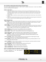
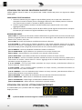
MP3 PLAYER/RECORDER OPERATING INSTRUCTIONS
If neither BLUETOOTH, PC nor USB pendrive is
connected the display shows:

12
The MODE button switches between the player’s operating modes:
USB PENDRIVE PLAYER
If a USB pendrive is inserted in the front panel USB port
the internal MP3 player start to play the first song
contained in the USB pendrive. The display shows at
first the number of the song and afterwards the time of
the current song, the order is always alphanumerical,
starting from the root folder to the subfolders.
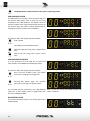
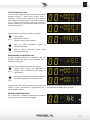
The buttons under the display operate as follow:
PLAY / PAUSE
The display shows the PAUSE status:
Skip to the previous song, then it plays it from
start.
Skip to the next song, then it plays it from
start.
USB PENDRIVE RECORDER
It is also possible to use the USB key to record the
mixer output. Press MODE until the display shows:
The buttons under the display operate as follow:
Press until the recorder starts, the display
shows the recording time progression:
Pressing REC button again the recorder
pauses the recording, the display shows:
The recorded files are contained in the USB pendrive
under the “JL_REC” folder, stored in progression with
the name “AC69nnnn.WAV”.
Note: all files are stored with 44100 sample rate,
16 bit, 2 channels.
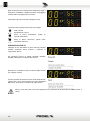
BLUETOOTH PLAYER
If a previous Bluetooth device is not already paired, the
display flashes:

13
From the Bluetooth preferences of your device, choose
the "PLAYMIX
" device, the display stops flashing
confirming the pairing and shows:
Pressing PLAY in your player the display shows:
The buttons under the display operate as follow:
PLAY / PAUSE
Skip to the previous song, then it plays it from
start.
Skip to the next song, then it plays it from
start.
PC AUDIO INTERFACE
Connect a PC using the USB port on the front panel,
wait some seconds and check the pc setting.
On your computer click on START, SETTING, SYSTEM,
SOUND, the Output device must be:
When you start playing some audio content on your
PC, the display changes:
It is also possible to set the mixer as the Input device
for your PC and then record the sound from the MAIN
MIX on the PC, using a recording software:
Note: the sound from the mixer can be recorded at up to 48000 sample rate, 16 bit, 2 channels.

14
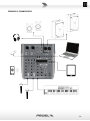
CONNECTION EXAMPLE

15
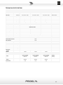
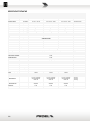
TECHNICAL SPECIFICATION
Model PLAYMIX6 PLAYMIX8 PLAYMIX10 Connectors
MONO INPUT CHANNEL
Mic Input sensitivity from -10 to -45 dB from -10 to -45 dB from -10 to -45 dB Balanced XLR-F
impedance 1 Kohm 1 Kohm 1 Kohm
Line Input
sensitivity
from +20 to -15 dB
from +20 to -15 dB
from +20 to -15 dB
Balanced JACK
impedance 20 Kohm 20 Kohm 20 Kohm
Lo cut 80Hz, 6dB/oct. 80Hz, 6dB/oct. 80Hz, 6dB/oct.
EQ HIGH (shelving) ±15 dB @ 12K Hz ±15 dB @ 12K Hz ±15 dB @ 12K Hz
MID (peaking)
±12 dB @ 250-6K Hz
±12 dB @ 250-6K Hz
±12 dB @ 250-6K Hz
LOW (shelving) ±15 dB @ 80 Hz ±15 dB @ 80 Hz ±15 dB @ 80 Hz
STEREO INPUT CHANNEL
Line Input sensitivity from +12 to -15 dB from +12 to -15 dB from +12 to -15 dB Balanced JACK
impedance
20 Kohm
20 Kohm
20 Kohm
Stereo Mini JACK
MASTER SECTION
MAIN MIX nom. out level +4 dBu +4 dBu +4 dBu Balanced XLR-M
C. ROOM output nom. out level +4 dBu +4 dBu +4 dBu Balanced JACK
SEND output
nom. out level
+4 dBu
+4 dBu
+4 dBu
Balanced JACK
HEADPHONES min. impedance 64 ohm 64 ohm 64 ohm Stereo JACK
Bluetooth Version 5.0, Audio Streaming
USB Player Stereo IN/OUT, 16-bit converter, 44,1 KHz sample rate Type A
DIGITAL EFFECT PROCESSOR
Effects 100 presets
A/D and D/A converters 24 bit
DSP resolution 24 bit
Controls 2-DIGIT display, DIAL, LEVEL
GENERAL SPECIFICATIONS
Maximum level all outputs +15 dBu
Crosstalk
meas. at 1 KHz
> 75 dB
HUM & Noise unweighted < 90 dB
THD + Noise at +4dB, 1kHz < 0,009 %
Dimensions
(WxHxD)
247 x 274 x 61 mm 331 x 274 x 61 mm 415 x 274 x 61 mm
Weight 1,80 kg 2,50 kg 3,00 kg
POWER REQUIREMENTS
Supply
use only supplied
AC/DC ADAPTER
5VDC 2A
use only supplied
AC/DC ADAPTER
5VDC 2A
use only supplied
AC/DC ADAPTER
5VDC 2A
EU Plug
US Plug
UK Plug
Mains Supply
Voltage 100-240 VAC (±10%)
50/60 Hz
100-240 VAC (±10%)
50/60 Hz
100-240 VAC (±10%)
50/60 Hz
Consumption
15 W
15 W
15 W

16
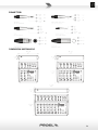
CONNECTORS
MECHANICAL DIMENSIONS

ISTRUZIONI DI SICUREZZA IMPORTANTI
Guarda questi simboli:
• Il lampo con la freccia all'interno di un triangolo equilatero ha lo scopo di avvisare l'utente della presenza di
"tensione pericolosa" non isolata all'interno della custodia del prodotto, che può essere di ampiezza sufficiente a
costituire un rischio di scossa elettrica per le persone.
• Il punto esclamativo all'interno di un triangolo equilatero avverte l'utente della presenza di importanti istruzioni
operative e di manutenzione (assistenza) nella documentazione che accompagna l'apparecchio.
1. Leggere queste istruzioni.
2. Conservare queste istruzioni.
3. Fare attenzione a tutti gli avvertimenti.
4. Seguire tutte le istruzioni.
5. Non usare questo dispositivo vicino all’acqua.
6. Pulire solo con uno strofinaccio asciutto.
7. Non bloccare alcuna fessura di ventilazione. Installare conformemente alle istruzioni del produttore.
8. Non installare nelle vicinanze di fonti di calore come radiatori, caloriferi, stufe o altri apparecchi (amplificatori
compresi) che generano calore.
9. Non annullare l’obiettivo di sicurezza delle spine polarizzate o con messa a terra. Le spine polarizzate hanno due
lame, con una più larga dell’altra. Una spina con messa a terra ha due lame e un terzo polo di terra. La lama larga o
il terzo polo servono per la sicurezza dell’utilizzatore. Se la spina fornita non è adatta alla propria presa, consultate
un elettricista per la sostituzione della spina.
10. Disporre il cavo di alimentazione in modo tale da essere protetto dal calpestio e da spigoli taglienti e che non possa
essere danneggiato, in particolare in prossimità delle spine, del cavo di prolunga e nel punto in cui il cavo di
alimentazione esce dall’apparecchio.
11. Usare solo dispositivi opzionali/accessori specificati dal produttore.
12. Usare solo con carrello, supporto, cavalletto, sostegno o tavola specificate dal produttore o acquistati con
l’apparecchio. Quando si usa un carrello, prestare attenzione, muovendo il carrello/la combinazione di apparecchi,
a non ferirsi.
13. Staccare la spina in caso di temporale o quando non si usa l’apparecchio per un lungo periodo.
14. Per l’assistenza tecnica rivolgersi a personale qualificato. L’assistenza tecnica è necessaria nel caso in cui l’unità sia
danneggiata, per es. per problemi del cavo di alimentazione o della spina, rovesciamento di liquidi od oggetti
caduti nell’apparecchio, esposizione alla pioggia o all’umidità, anomalie di funzionamento o cadute
dell’apparecchio.
15. Avvertenza: per ridurre il rischio di incendi o scosse elettriche, non esporre questo apparecchio alla pioggia o
all'umidità.
16. Non esporre questa apparecchiatura a gocciolamenti o schizzi e assicurarsi che nessun oggetto riempito di liquidi,
come i vasi, venga posta sull'apparecchiatura.
17. Per scollegare completamente questo apparato dalla rete elettrica AC, scollegare la spina dell’adattatore AC dalla
presa elettrica AC.
18. La spina di alimentazione del cavo di alimentazione deve rimanere facilmente accessibile.
19. Questo apparecchio contiene tensioni potenzialmente letali. Per evitare scosse elettriche o rischi, non rimuovere
lo chassis, il modulo di ingresso o le coperture degli ingressi AC. All'interno non ci sono parti riparabili dall'utente.
Per l'assistenza, rivolgersi a personale di assistenza qualificato.
20. Gli apparati trattati in questo manuale non sono destinati ad ambienti esterni ad alta umidità. L'umidità può
danneggiare l’elettronica interna e causare la corrosione dei contatti elettrici e delle parti metalliche. Evitare di
esporre l’apparato all'umidità diretta.
21. Utilizzare solo l'ADATTATORE AC fornito con l'unità per collegare la console alla rete elettrica.
22. Utilizzare solo il cavo USB tipo A – tipo A fornito con l'unità per collegare l'ADATTATORE AC/DC alla console.
23. L'ADATTATORE AC/DC è conforme a tutti gli standard di sicurezza applicabili.
24. All'interno dell'ADATTATORE AC/DC non sono presenti parti riparabili, in caso di guasto sostituirlo con uno nuovo.

18
Il marchio riportato sul prodotto o sulla documentazione indica che il prodotto non deve essere smaltito con altri rifiuti
domestici al termine del ciclo di vita. Per evitare eventuali danni all’ambiente si invita l’utente a separare questo
prodotto da altri tipi di rifiuti e di riciclarlo in maniera responsabile per favorire il riutilizzo sostenibile delle risorse
materiali. Gli utenti domestici sono invitati a contattare il rivenditore presso il quale è stato acquistato il prodotto o
l’ufficio locale preposto per tutte le informazioni relative alla raccolta differenziata e al riciclaggio per questo tipo di
prodotto. Gli utenti aziendali sono invitati a contattare il proprio fornitore e verificare i termini e le condizioni del
contratto di acquisto. Questo prodotto non deve essere smaltito unitamente ad altri rifiuti commerciali.
DICHIARAZIONE DI CONFORMITÀ
Il prodotto è conforme alle seguenti direttive europee:
EMC 2014/30/EU, RED 2014/53/EU, LVD 2014/35/EU, RoHS 2011/65/EU and WEEE 2012/19/EU.
AVVERTIMENTO EN 55032 (CISPR 32)
Sotto il disturbo EM, il rapporto segnale-rumore verrà modificato oltre i 10 dB.
GARANZIA LIMITATA
Proel garantisce tutti i materiali, la lavorazione e il corretto funzionamento di questo prodotto per un periodo di due anni dalla data
di acquisto originale. I difetti rilevati entro il periodo di garanzia sui prodotti venduti, attribuibili a materiali difettosi o difetti di
costruzione, devono essere tempestivamente segnalati al proprio rivenditore o distributore, allegando evidenza scritta della data di
acquisto e descrizione del tipo di difetto riscontrato. Sono esclusi dalla garanzia difetti causati da uso improprio o manomissione.
Proel constata tramite verifica sui resi la difettosità dichiarata, correlata all’appropriato utilizzo, e l’effettiva validità della garanzia;
provvede quindi alla sostituzione o riparazione dei prodotti, declinando tuttavia ogni obbligo di risarcimento per danni diretti o
indiretti eventualmente derivanti dalla difettosità.
• L’imballo è stato sottoposto a test di integrità secondo la procedura ISTA 1A. Si raccomanda di controllare il prodotto subito
dopo l’apertura dell’imballo..
• Se vengono riscontrati danni informare immediatamente il rivenditore. Conservare quindi l’imballo completo per permetterne
l’ispezione.
• Proel declina ogni responsabilità per danni causati dal trasporto.
• Le merci sono vendute “franco nostra sede” e viaggiano sempre a rischio e pericolo del distributore.
• Eventuali avarie e danni dovranno essere contestati al vettore. Ogni reclamo per imballi manomessi dovrà essere inoltrato
entro 8 giorni dal ricevimento.
CONDIZIONI D'USO
Proel non si assume alcuna responsabilità per danni causati a terzi a causa di installazione impropria, uso di parti di ricambio non
originali, mancanza di manutenzione, manomissione o uso improprio di questo prodotto, incluso il mancato rispetto di standard di
sicurezza accettabili e applicabili. Proel raccomanda vivamente di sospendere questo cabinet per altoparlanti tenendo in
considerazione tutte le normative nazionali, federali, statali e locali vigenti. Il prodotto deve essere installato da personale
qualificato. Si prega di contattare il produttore per ulteriori informazioni.

19
SOMMARIO – ITALIANO
INTRODUZIONE ................................................................................................................................. 20
DESCRIZIONE ..................................................................................................................................... 20
ISTRUZIONI ........................................................................................................................................ 20
1. Ingresso MIC-XLR ................................................................................................................... 20
2. Ingresso LINE JACK ................................................................................................................. 20
3. -20dB PAD interruttore ........................................................................................................... 20
4. +48V interruttore alimentazione phantom ............................................................................. 22
5. +48V LED ................................................................................................................................ 22
6. PEAK rilevatore di picco .......................................................................................................... 22
7. GAIN controllo di guadagno ................................................................................................... 22
8. LO CUT filtro elimina bassi ...................................................................................................... 22
9. HIGH equalizzatore controllo alti ............................................................................................ 22
10. MID equalizzatore controllo medi ....................................................................................... 22
11. FREQ controllo frequenza ................................................................................................... 22
12. LOW equalizzatore controllo bassi ...................................................................................... 22
13. FX/AUX controllo mandata ................................................................................................. 23
14. PAN controllo panoramico .................................................................................................. 23
15. FADER LEVEL controllo di livello del canale ......................................................................... 23
16. LINE-JACK (L MONO – R) ingressi jack ................................................................................. 23
17. STEREO IN ingresso MINI JACK ............................................................................................ 23
18. BAL controllo bilanciamento ............................................................................................... 23
19. STEREO CHANNEL LEVEL controllo livello ........................................................................... 23
20. FX/AUX controllo mandata ................................................................................................. 23
21. AUX SEND uscita jack .......................................................................................................... 23
22. FX PRESETS selettore effetto ............................................................................................... 23
23. FX DISPLAY .......................................................................................................................... 24
24. FX LEVEL controllo livello effetto......................................................................................... 24
25. MP3 PLAYER/RECORDER ..................................................................................................... 24
26. PORTA USB .......................................................................................................................... 24
27. CH/USB BT selettore ........................................................................................................... 24
28. MAIN MIX livello uscita MIX ............................................................................................... 24
29. MAIN MIX L & R uscite XLR bilanciate ................................................................................. 24
30. C.ROOM/PHONES livello uscita cuffia e c.room .................................................................. 25
31. PHONES uscita jack stereo per cuffia .................................................................................. 25
32. C.ROOM L & R uscite jack control room .............................................................................. 25
33. L & R LEVEL METERS indicatori di livello ............................................................................. 25
34. ON LED indicatore acceso/spento ....................................................................................... 25
35. POWER interruttore di accensione ..................................................................................... 25
36. DC IN 5V 1A ingresso presa di alimentazione ..................................................................... 25
ISTRUZIONI PER L'USO DEL PROCESSORE DI EFFETTI DSP ................................................................. 26
ISTRUZIONI PER L'USO DEL LETTORE/REGISTRATORE MP3 ............................................................... 26
ESEMPIO DI CONNESSIONE ............................................................................................................... 29
SPECIFICHE TECNICHE ....................................................................................................................... 30
CONNETTORI ..................................................................................................................................... 31
DIMENSIONI MECCANICHE ............................................................................................................... 31

20
INTRODUZIONE
Grazie per aver scelto un prodotto PROEL e della fiducia riposta nel nostro marchio, sinonimo di accuratezza,
elevata qualità ed affidabilità. Tutti i nostri prodotti sono conformi alle normative CE per utilizzazione
continua in impianti di diffusione sonora.
DESCRIZIONE
PLAYMIX è una serie di mixer creati da PROEL per offrire in un formato molto compatto e attraente un’alta densità di
ingressi, una serie completa di funzioni ed una superiore qualità audio, ad un livello di prezzo molto conveniente.
I mixer PLAYMIX sono disponibili in 3 modelli, con le stesse funzioni di canale e master, ma con 6, 8 e 10 canali
rispettivamente. I canali mono MIC/LINE includono preamplificatori microfonici a basso rumore e ad alta dinamica,
equalizzatori a tre bande con MID parametrici e filtro HPF, e fader da 60 mm per un controllo completo del suono.
Tutti i modelli sono dotati di un'avanzata sezione DIGITALE con display LCD, che comprende:
- Un DSP integrato a 24 bit di alta qualità, con 100 preset da studio di effetti singoli e combinati
(RIVERBERO, DELAY, MODULAZIONI)
- Un'interfaccia audio USB stereo a 48 KHz per la riproduzione/registrazione tramite connessione al PC
- Un lettore MP3 integrato dalla chiave di memoria USB o dall'interfaccia BLUETOOTH
- Registrazione stereo su chiave di memoria USB
Accuratamente progettati e ingegnerizzati in Italia da PROEL, i mixer PLAYMIX sono alloggiati in robuste scocche
che garantiscono una lunga durata per un uso a prova di palcoscenico, e offrono in un formato ultracompatto le
prestazioni di console professionali, con un suono pulito e preciso per una vasta gamma di applicazioni.
ISTRUZIONI
NOTA: i tre modelli si differenziano solo per il numero dei canali MONO, rispettivamente 2, 4 e 6. I
canali STEREO (2) e la sezione MASTER sono gli stessi per tutti e tre i modelli. Le seguenti istruzioni
si riferiscono alla numerazione dei canali di PLAYMIX6.
1. Ingresso MIC/LINE XLR
È un connettore XLR femmina, in grado di accettare un segnale bilanciato da microfoni, strumenti e apparati
con uscita di linea. L’ingresso XLR ha i seguenti terminali:
Pin 1 = schermo o massa
Pin 2 = + positivo o “caldo”
Pin 3 = - negativo o “freddo”
2. Ingresso MIC/LINE JACK
È un connettore JACK femmina, in grado di accettare un segnale bilanciato da microfoni, strumenti e apparati
con uscita di linea. L’ingresso JACK ha i seguenti terminali:
Tip (punta) = + positivo o “caldo”
Ring (anello) = - negativo o “freddo”
Sleeve (manicotto) = schermo o massa
Quando si collega un segnale sbilanciato, le terminazioni sono le seguenti:
Tip (punta) = + positivo o “caldo”
Sleeve (manicotto) = schermo o massa
3. LINE/-30dB interruttore
Premendo questo pulsante viene attivata un'attenuazione di 30dB su entrambi gli ingressi XLR e JACK.
La pagina si sta caricando...
La pagina si sta caricando...
La pagina si sta caricando...
La pagina si sta caricando...
La pagina si sta caricando...
La pagina si sta caricando...
La pagina si sta caricando...
La pagina si sta caricando...
La pagina si sta caricando...
La pagina si sta caricando...
La pagina si sta caricando...
La pagina si sta caricando...
-
 1
1
-
 2
2
-
 3
3
-
 4
4
-
 5
5
-
 6
6
-
 7
7
-
 8
8
-
 9
9
-
 10
10
-
 11
11
-
 12
12
-
 13
13
-
 14
14
-
 15
15
-
 16
16
-
 17
17
-
 18
18
-
 19
19
-
 20
20
-
 21
21
-
 22
22
-
 23
23
-
 24
24
-
 25
25
-
 26
26
-
 27
27
-
 28
28
-
 29
29
-
 30
30
-
 31
31
-
 32
32


PROEL SOUND PLAYMIX8 Manuale utente
- Categoria
- Attrezzatura musicale
- Tipo
- Manuale utente
in altre lingue
- English: PROEL SOUND PLAYMIX8 User manual