
AC Master
PURE SINE WAVE INVERTER
12/2500, 24/2500, 12/3500
EN
USER’S AND INSTALLATION MANUAL
NL
GEBRUIKERS
- EN INSTALLATIEHANDLEIDING
DE
BEDIENUNGS
- UND INSTALLATIONSANLEITUNG
FR
MANUEL D'INSTALLATION ET
D'UTILISATION
IT
MANUALE DI USO E MANUTEN
ZIONE
ES
MANUAL DEL USUARIO Y DE INSTALACIÓN
10000011809/1

2
AC Master
Product description
The AC Master is a sine wave inverter. The AC Master converts DC energy from the battery into AC
output power. The AC Master 2500-3500 is equipped with an AC transfer switch and is suitable for
creating systems with multiple units in parallel or 3 phase configuration.
Productbeschrijving
De AC Master is een sinusomvormer. De AC Master vormt gelijkspanning (DC) van de accu om
naar wisselspanning (AC-uitgang). De AC Master 2500-3500 is uitgerust met een AC-
omschakelautomaat. Deze is geschikt voor het creëren van systemen met meerdere parallelle units
of een drie fasen configuratie.
Produktbeschreibung
Der AC Master ist ein Sinus-Wechselrichter. Der AC Master wandelt Gleichstrom von der Batterie in
Wechsel-Ausgangsspannung um. Der AC Master 2500-3500 ist mit einem Wechselstrom-
Umschalter ausgestattet und eignet sich für die Einrichtung von Systemen mit mehreren Einheiten
in Parallelkonfiguration oder 3-phasiger Konfiguration.
Description de l’appareil
L'AC Master est un convertisseur sinusoïdal. L'AC Master convertit l'énergie CC de la batterie en
puissance de sortie CA. L'AC Master 2500-3500 est équipé d'un commutateur de transfert CA et
peut être utilisé pour créer des systèmes à plusieurs unités en configuration en parallèle ou
triphasée.
Descrizione del prodotto
AC Master è un inverter di onda sinusoidale. AC Master converte l’energia CC dalla batteria in
energia di uscita CA. L’AC Master 2500-3500 è dotato di un interruttore di trasferimento CA ed è
adatto per la creazione di sistemi con più unità in parallelo o con una configurazione trifase.
Descripción del producto
El AC Master es un inversor de onda sinusoidal. El AC Master convierte la energía de CC de la
batería en corriente de salida CA. El AC Master 2500-3500 está equipado con un interruptor de
transferencia de CA y es adecuado para crear sistemas con múltiples unidades en paralelo o en
configuración trifásica.

AC Master
3
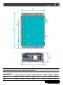
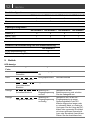
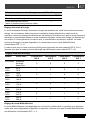
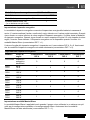
Dimensions
Afmetingen/Abmessungen/Dimensions/Dimensioni/Dimensiones
Model
Model/Modell/Modèle/
Modello/Modelo
A (mm) B (mm) C (mm) D (mm) E (mm) F (mm) G (mm) H (mm)
2500 436,0 240,0 95,6 268,6 8,5 11,5 128,0 283,0
3500
496,0 240,0 125,6 268,6 8,5 11,5 128,0 283,0

4
AC Master

AC Master
5
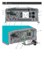
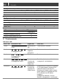
Front panel
Frontpaneel/Frontpanel/Panneau avant /Frontalino/Panel frontal
1 Remote port (RS-232)
Afstandsbedieningspoort (RS-232)/Anschluss Fernbedienung (RS-232)/Port distant (RS-232)/Porta a distanza
(RS-232)/Puerto remoto (RS-232)
2 Terminal for remote switch and CAN termination
Aansluiting voor afstandsbediening en CAN-bus afsluitweerstand/Anschluss für Fernbedienungsschalter und
CAN-Terminierung/Borne pour commutateur à distance et terminaison CAN/Terminale per interruttore remoto e
terminazione CAN/Terminal para interruptor remoto y terminación CAN
3 CAN1 port *
CAN1-poort */CAN1-Anschluss*/Port CAN1*/Porta CAN1*/Puerto CAN1*
4 CAN2 port *
CAN2-poort */CAN2-Anschluss*/Port CAN2*/Porta CAN2*/Puerto CAN2*
5 AC input circuit breaker 20 Amp
AC-ingang zekering 20 Amp/AC-Eingangsschutzschalter 20 A/Disjoncteur d'entrée CA 20 A/Interruttore ingresso
CA 20 Amp/Interruptor de entrada CA de 20 A
6 AC input
AC-ingang/AC-Eingang/Entrée CA/Ingresso CA/Entrada CA
7 AC output
AC-uitgang/AC-Ausgang/Sortie CA/Uscita CA/Salida CA
8 Chassis ground terminal
Aarde-aansluiting/Erdungspunkt/Point de masse/Punto di messa a terra/Terminal de conexión a tierra del chasis
9 AC output socket
AC-uitgang (contactdoos)/AC-Ausgangsdose/Prise de sortie CA/Presa uscita CA/Toma de salida CA
10 Battery input (DC) +
Accu-ingang + /Batterieeingang + /Entrée de la batterie + /Ingresso batteria + /Entrada de batería +
11 Battery input (DC) -
Accu-ingang - /Batterieeingang - /Entrée de la batterie - /Ingresso batteria - /Entrada de batería -
12 LCM port **
LCM-poort **/LCM-Anschluss **/Port LCM **/Porta LCM**/Puerto LCM **
13 DIP switches
DIP switches/DIP-Schalter/Commutateurs DIP/Commutatori DIP/Conmutadores DIP
14 LED indicator
LED/LED-Anzeige/Voyant DEL/Indicatore LED/Indicador LED
15 Main switch
Hoofdschakelaar/Hauptschalter/Interrupteur principal/Interruttore principale/Interruptor principal
16 Hard-wire connection for AC output and AC input
AC-uitgang (vaste installatie) en AC-ingang/Festverkabelte Verbindung für AC-Ausgang und AC-Eingang /
Connexion câblée pour sortie et entrée CA/Collegamento cablato per uscita CA e ingresso CA/Conexión
cableada para salida CA y entrada CA
17 Internal grounding cable (GND)
Interne aardingskabel (GND)/Internes Erdungskabel (GND)/Câble de terre interne (GND)/Cavo di messa a terra
interno (GND)/Cable interno de puesta a tierra (GND)
18 Internal grounding cable (Inverter Neutral)
Interne aardingskabel (Inverter Neutral)/Internes Erdungskabel (Inverter Neutral)/Câble de terre interne (Inverter
Neutral)/Cavo di messa a terra interno (Inverter Neutral)/Cable interno de puesta a tierra (Inverter Neutral)

6
AC Master
* This is not a MasterBus port. Do not connect a CAN port to a MasterBus network. This will cause
hardware damage.
** LCM is not supported by Mastervolt.
* Dit is geen MasterBus-poort. Verbind een CAN-poort niet met een MasterBus-netwerk. Dit leidt tot schade aan de
hardware.
** LCM wordt niet ondersteund door Mastervolt.
* Kein MasterBus-Anschluss. Ein CAN-Anschluss darf nicht mit einem MasterBus-Netzwerk verbunden werden.
Andernfalls wird die Hardware beschädigt.
** LCM wird von Mastervolt nicht unterstützt.
* Ce n'est pas un port MasterBus. Ne connectez pas de port CAN à un réseau MasterBus. Cela endommagerait le
matériel.
** LCM n'est pas pris en charge par Mastervolt.
*Non si tratta di una porta MasterBus. Non collegare un porta CAN ad una rete MasterBus. Questo provocherà danni
all’hardware.
** LCM non è supportato da Mastervolt.
* No se trata de un puerto MasterBus. No conecte puertos CAN a una red MasterBus. Causaría daños en los
components.
** Mastervolt no admite LCM.
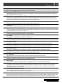
Identification label
Serienummersticker/Typenschild/Étiquette d'identification/Etichetta di identificazione/Etiqueta de
identificación

AC Master
7
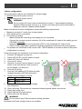
Installation instructions
This section provides a step by step instruction of the stand-alone installation of the AC
Master 2500/3500. Please read the entire manual for instructions on safety, grounding,
configuration settings, additional features and creating systems with multiple units.
Read the safety instructions! See section 1 on page 13.
Use isolated tools!
Installatie instructies
Dit hoofdstuk biedt stapsgewijze instructies voor de installatie van een enkele AC
Master 2500/3500. Lees de hele handleiding voor instructies over veiligheid, aarding,
configuratie-instellingen, aanvullende functies en het maken van systemen met
meerdere units.
Lees de veiligheidsinstructies! Zie hoofdstuk 1 op pagina 29.
Gebruik geïsoleerde gereedschappen!
Installationsanweisungen
Dieser Abschnitt enthält eine schrittweise Anleitung zur Installation eines unabhängigen
AC Master 2500/3500. Bitte machen Sie sich mit dem Inhalt der gesamten Anleitung
vertraut, insbesondere den Hinweisen zu Sicherheit, Erdung,
Konfigurationseinstellungen, zusätzlichen Funktionen und Einrichtung von Systemen
mit mehreren Einheiten.
Lesen Sie die Sicherheitsanweisungen! Siehe Abschnitt 1 auf Seite 45.
Verwenden Sie isolierte Werkzeuge!
Instructions d’installation
Cette section fournit les instructions étape par étape pour l'installation de l'AC Master
2500/3500 autonome. Veuillez lire entièrement le manuel pour connaître les instructions
en matière de sécurité et de mise à la terre, les réglages de configuration, les fonctions
supplémentaires et pour créer des systèmes avec plusieurs unités.
Lire les directives de sécurité! Voir la section 1 à la page 61.
Utiliser des outils isolés!
Istruzioni di installazione
Questa sezione fornisce istruzioni passo passo relative all’installazione indipendente di
AC Master 2500/3500. Leggere l’intero manuale per le istruzioni sulla sicurezza, la
messa a terra, le impostazioni di configurazione, le funzioni aggiuntive e la creazione di
sistemi con unità multiple.
Leggere le istruzioni di sicurezza! Vedere la sezione 1 a pagina 77.
Utilizzare utensili isolati!
Instrucciones de instalación
Esta sección ofrece instrucciones detalladas para la instalación de un AC Master
2500/3500 independiente. Lea todo el manual para obtener instrucciones de
seguridad, puesta a tierra, ajustes de configuración, características adicionales y
creación de sistemas de varias unidades.
Lea las instrucciones de seguridad! Consulte la sección 1 de la página 93.
¡Use herramientas aisladas!

8
AC Master
1. Disconnect power supplies.
Verwijder de stroomvoorzieningen.
Unterbrechen Sie die Stromversorgung.
Déconnecter les alimentations électriques.
Scollegare le alimentazioni.
Desconecte la fuente de alimentación.
2. Switch OFF the AC Master.
Schakel de AC Master naar OFF (uit).
Schalten Sie den Schalter des AC Master auf OFF.
Mettre l'AC Master sur OFF.
Spegnere AC Master.
Sitúe el interruptor del AC Master en la posición OFF.
3. Select a location that complies with section 6 on page 14.
Selecteer een locatie die overeenstemt met hoofdstuk 6 op pagina 30.
Wählen Sie einen Standort aus, der den Anforderungen in Abschnitt 6 auf Seite 46 entspricht.
Choisir un emplacement conforme à la section 6 de la page 62.
Selezionare una posizione conforme alla sezione 6 a pagina 78.
Seleccione una ubicación que cumpla con la sección 6 de la página 94.

AC Master
9
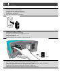
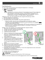
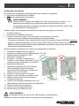
4. Mount the AC Master with four screws to a solid surface.
Monteer de AC Master met vier schroeven op een stevige ondergrond.
Montieren Sie den AC Master mit 4 Schrauben an eine feste Wand.
Fixer l’AC Master sur une surface solide à l’aide des quatre vis.
Fissare l’AC Master su una superficie solida con quattro viti.
Monte de AC Master con cuatro tornillos en una superficie sólida.
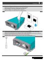
5. Connect the chassis ground terminal to the central grounding point of the vehicle/ship.
Sluit de aarde-aansluiting aan op het centrale massapunt van het schip/voertuig.
Schließen Sie den Erdungspunkt des AC Master an den zentralen Erdungspunkt des Fahrzeugs / Schiffes an.
Connecter le point de masse au point de masse central du véhicule/bateau.
Collegare il punto di messa a terra al punto di messa a terra del veicolo/della barca.
Conecte el punto de conexión a tierra al punto de conexión a tierra central del vehículo/barco.

10
AC Master
6. Optional: Connect control panel or remote switch, see section 6 on page 14.
Optioneel: Sluit het bedieningspaneel of de afstandsschakelaar aan, zie hoofdstuk 6 op pagina 30. Optional:
Schließen Sie das Bedienungspanel oder den Fernbedienungsschalter an, siehe Abschnitt 6 auf Seite 46.
En option : Connecter un panneau de contrôle ou un commutateur à distance, voir la section 6 à la page 62.
Opzionale: Collegare il pannello di controllo o l'interruttore a distanza, vedere la sezione 6 a pagina 78.
Opcional: Conecte el panel de control o el interruptor remoto. Consulte la sección 6 de la página 94.
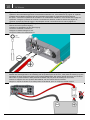
7. Connect the battery to the DC input.
Sluit de accu aan op de DC-ingang.
Schließen Sie die Batterie an den DC-Eingang.
Connecter la batterie à l’entrée CC.
Collegare la batteria all'ingresso CC.
Conecte la batería a la entrada de CC.
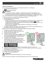
8. Integrate a fuse holder in the positive battery wire, but do not place the fuse yet.
Monteer een zekeringhouder in de bedrading naar de positieve pool van de accu, maar plaats de zekering nog niet.
Integrieren Sie einen Sicherungs-halter in das positive Batteriekabel, aber setzen Sie die Sicherung noch nicht ein.
Raccorder un porte-fusible au câble positif de la batterie. Ne pas placer le fusible pour le moment.
Inserire un supporto nel cavo positivo della batteria, ma non inserire ancora il fusibile.
Integre un soporte de fusible en el cable positivo de la batería, pero no coloque el fusible todavía.

AC Master
11
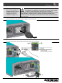
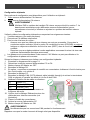
9. Connect the AC load.
Sluit de AC belasting aan.
Schließen Sie die AC-Last an.
Connecter la charge CA.
Collegate il carico CA.
Conecte la carga de CA.
See section 5 on page 14 for instructions on neutral grounding.
Zie hoofdstuk 5 op pagina 30 voor instructies over aarding van de nulleider.
Hinweise zur Neutralleitererdung siehe Abschnitt 5 auf Seite 46.
Voir la section 5 à la page 62 pour les instructions relatives à la mise à la terre du neutre.
Vedere la sezione 5 a pagina 78 per le istruzioni sulla messa a terra del neutro.
Consulte la sección 5 de la página 94 para obtener instrucciones acerca de la puesta
a tierra de neutro.
AC socket
AC-contactdoos/AC-Steckdose /Prise CA/Presa CA/Toma de CA
AC hard-wired
AC vaste installatie/AC festverkabelt/CA câblé/Cablato CA/CA cableado

12
AC Master
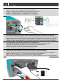
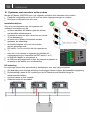
10. Optional: Connect AC input, see section 7 on page 16.
Optioneel: Verbind de AC-ingang, zie hoofdstuk 7 op pagina 32.
Optional: Verbinden Sie den AC-Eingang, siehe Abschnitt 7 auf Seite 48.
En option : connexion de l'entrée CA, voir la section 7 à la page 64.
Opzionale: collegare l’ingresso CA, vedere la sezione 7 a pagina 80.
Opcional: conecte la entrada CA; consulte la sección 7 de la página 96.
11. Set the desired output voltage and other configuration settings, see section 8 on page 18.
Stel de gewenste uitgangsspanning en andere configuratie-instellingen in, zie hoofdstuk 8 op pagina 34.
Stellen Sie die gewünschte Ausgangsspannung und andere Konfigurationseinstellungen ein, siehe Abschnitt 8 auf Seite 50.
Réglage de la tension de sortie souhaitée et d'autres réglages de configuration, voir la section 8 à la page 66.
Impostare la tensione di uscita desiderata e altre impostazioni di configurazione, vedere la sezione 8 a pagina 82.
Consulte la tensión de salida deseada y otros ajustes de configuración; consulte la sección 8 en la página 97.
12. Check all wiring. If all wiring is OK: Place the inverter fuse.
Controleer alle bedrading. Indien de bedrading juist is aangesloten: Plaats de omvormerzekering.
Überprüfen Sie die gesamte Verkabelung. Falls OK: Setzen Sie die DC-Sicherung ein.
Vérifier tout le câblage. Si OK : Positionner le fusible du convertisseur.
Ispezionare tutti i cavi. Se sono OK: Collocare il fusibile dell'inverter.
Si todo el cableado es correcto: Coloque el fusible del inverso.
13. Switch ON the AC Master. In case of remote operation choose REMOTE.
Schakel de AC Master naar ON (aan). In geval van bediening op afstand, kies REMOTE.
Schalten Sie den Schalter des AC Master auf ON. Schalten Sie im Falle der Fernbedienung auf REMOTE.
Mettre l'AC Master sur ON. En cas de fonctionnement à distance, choisir REMOTE.
Mettere su ON l´AC Master. In caso di utilizzo a distanza, scegliere REMOTE.
Sitúe el interruptor del AC Master en la posición ON. En caso de funcionamiento remoto, seleccione REMOTE.

ENGLISH
13
1. Safety instructions
WARNING!
Read the entire manual before using the AC Master. Keep the manual at a safe location for
future reference.
Use the AC Master following the instructions and specifications stated in this manual.
Connections and safety features must be executed according to the locally applicable
regulations.
Operation of the AC Master without proper grounding may lead to hazardous situations!
Use DC-cables with an appropriate size, see recommended wire sizes DC in section 6.
Integrate an appropriate fuse in the positive wiring and place it nearby the battery, see technical
specifications table on page 27.
If the positive and negative wires on the DC-input (battery) are exchanged, the AC Master will
be damaged. Damage of this kind is not covered by guarantee. Check whether all connections
are connected correctly before placing the fuse.
Do not connect the AC-output of the AC Master to an incoming AC source.
Never open the housing as high voltages may be present inside!
2. Liability
Mastervolt cannot be held liable for:
Consequential damage resulting from the use of the AC Master.
Possible errors in the included manual and the consequences of these.
Use that is inconsistent with the purpose of the product.
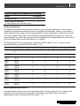
3. Warranty
Mastervolt assures the product warranty of the AC Master during two years after purchase, on the
condition that the product is installed and used according to the instructions in this manual.
Installation or use not according to these instructions may result in under performance, damage or
failure of the product and may void this warranty. The warranty is limited to the cost of repair and/or
replacement of the product. Costs for labour or shipping are not covered by this warranty.
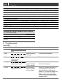
4. Correct disposal of this product
(Waste Electrical & Electronic Equipment)
This product is designed and manufactured with high quality materials and
components, which can be recycled and reused. When this crossed-out wheeled bin
symbol is attached to a product, it means the product is covered by the European
Directive 2012/19/EU.
Please be informed about the local separate collection system for electrical and electronic products.
Please act according to your local rules and do not dispose of your old products with your normal
household waste. The correct disposal of your old product will help prevent potential negative
consequences to the environment and human health.

14
ENGLISH
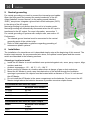
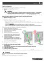
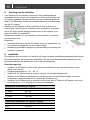
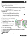
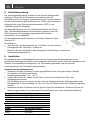
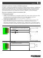
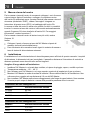
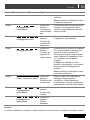
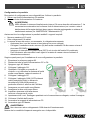
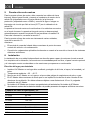
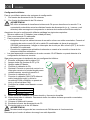
5. Neutral grounding
For neutral grounding you need to connect the internal ground cables:
Open the front panel and connect the neutral conductor of the AC
output (labelled ‘Inverter Neutral’) to the safety ground (labelled
‘GND’), see picture. Integrate a ground fault circuit-interrupter (GFCI)
in the wiring of the AC output.
Neutral grounding is only active when the unit is in Inverter mode.
Neutral grounding will automatically disconnect when the AC input is
transferred to the AC output. For more information, see section 7.
For neutral grounding of systems with multiple units, see section 10.
Furthermore:
The chassis ground terminal must be connected to the central
grounding point of the vehicle/ ship.
Refer to locally applicable regulations regarding grounding of
autonomous power systems.
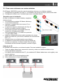
6. Installation
The installation of a stand-alone unit is described step-by-step at the beginning of this manual. The
location requirements, the recommended wire sizes, the optional control panel and the remote
switch are described in the following sections.
Choosing a location to install
Install the AC Master in a well-ventilated room protected against rain, snow, spray, vapour, bilge,
moisture and dust.
Ambient temperature: –25 ... 40 °C / –13…104 °F.
Never use the AC Master at a location where there is danger of gas or dust explosions.
Mount the AC Master in such a way that obstruction of the airflow through the ventilation
openings is prevented. No objects must be located within a distance of 10 cm / 4 inch around
the AC Master.
Do not install the AC Master in the same compartment as the batteries. Do not mount the AC
Master straight above the batteries because of possible corrosive sulphur fumes.
Recommended wire sizes DC input
Model
Minimum cross section
12/2500 95 mm
2
24/2500 50 mm
2
12/3500 120 mm
2
Recommended wire sizes AC input / output
Model Minimum cross section
output
2500 2,50 mm
2
3500 2,50 mm
2

ENGLISH
15
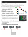
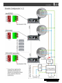
AC Master Inverter Control Panel (optional)
Optionally an AC Master Inverter Control Panel (article number: 70405080) is connected to the
remote port (RS-232). In case of a system with multiple units: Always connect the control panel to
the Master unit. Before using the control panel, make sure the main switch of the connected unit is
at “REMOTE” position before startup.
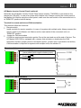
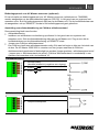
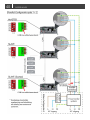
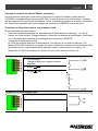
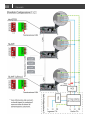
Terminal for remote switch and CAN termination
This terminal offers two functions:
Remote switch
Install a switch for remote operation. In case of a system with multiple units: Always connect the
remote switch to the Master unit. Make sure the main switch of the connected unit is at
“REMOTE” position.
Jumper for CAN termination
A CAN bus requires two termination points. One at the start and one at the end of the bus. The
AC Master 2500-3500 is equipped with a jumper that activates or deactivates the CAN
termination resistor (jumper closed = termination active ; jumper open
= termination not active).
CAN termination is required for systems with multiple units, see section 10.
Remote switch
1 Ground (GND)
(same polarity with negative battery input)
2
Enable
− (ENB)
3
Enable
+ (ENB)
Jumper for CAN termination
4 Jumper slot
5 Jumper slot

16
ENGLISH
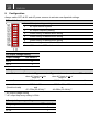
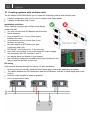
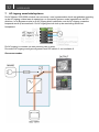
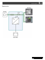
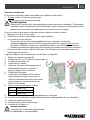
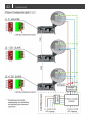
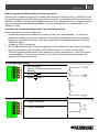
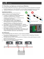
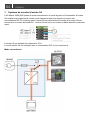
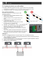
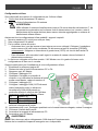
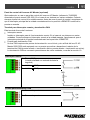
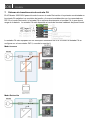
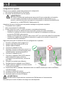
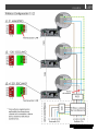
7. AC input transfer system
The AC Master 2500-3500 switches from Inverter mode to Bypass mode if the power provided on
the AC input meets the voltage and frequency requirements as set with the DIP switches. In Bypass
mode the AC input is directly connected to the AC output, saving battery power. The AC input is
available on the hard-wire terminal behind the front panel.
The AC input is equipped with a 20 Amp circuit breaker.
The AC input mode is configured with DIP switch 2, see section 8.
Inverter mode

ENGLISH
17
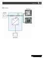
Bypass mode

18
ENGLISH
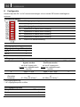
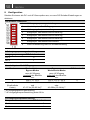
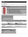
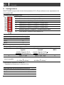
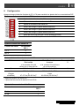
8. Configuration
Always switch OFF all DC and AC power sources to activate new dipswitch settings.
DIP switch functions
1 AC output voltage setting
2 AC input transfer system
3 AC output frequency setting
4 Power saving or Master/Slave setting
5 Power saving or Master/Slave setting
6 Power saving or Master/Slave setting
7 Power saving mode or Master/Slave mode
8 LCM remote or DIP switch control
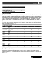
AC output voltage setting
Output voltage DIP switch 1
230 V 0
240 V 1
AC input transfer system
Mode Inverter- to Bypass mode
when AC input is in the
range of:
Bypass- to Inverter mode
when AC input is out of
range of:
DIP switch 2
0 230V* +/-12% 230V* +12%, -25% 0
1
(Sensitive loads)
230V* +/-12%
and
47~57Hz (53~63Hz)**
230V* +12%, -25%
or
46~58Hz (52~64Hz)**
1
* AC output voltage setting
** AC output frequency setting is 60Hz
AC output frequency setting
Frequency
DIP switch 3
50 Hz 0
60 Hz 1

ENGLISH
19
Power Saving mode or Master/Slave mode select
Mode DIP switch 7
Power Saving Mode ON 0
Master/Slave mode ON
(in a system with multiple units)
1
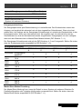
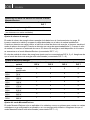
Power Saving setting
The Power Saving mode saves energy from the battery in no load operation. The inverter scans the
output and compares the detected load to the set threshold value. When a load is detected which is
lower than the Power Saving threshold value, the inverter switches into Power Saving Mode. When
a load is detected which is approximately 2~3 times the threshold value, the inverter is switched
back on. Power Saving is not available when the inverter is in Master/Slave mode (DIP switch 7 =
1).
The Power Saving threshold value is set with DIP switch 4, 5 and 6. Make sure that Power Saving
Mode is selected (DIP switch 7 = 0).
Power Saving setting
Model Threshold
value
DIP switch 4 DIP switch 5 DIP switch 6 DIP switch 7
2500/3500 Power saving
disabled
0 0 0 0
2500
3500
50 W
70 W
1 0 0 0
2500
3500
75 W
105 W
0 1 0 0
2500
3500
100 W
140 W
1 1 0 0
2500
3500
125 W
175 W
0 0 1 0
2500
3500
150 W
210 W
1 0 1 0
2500
3500
175 W
245 W
0 1 1 0
2500
3500
200 W
280 W
1 1 1 0
Master/Slave mode setting
Master/Slave mode is only applicable when the unit is used in a system with multiple units for
parallel configuration or 3 phase configuration. Make sure that Master/Slave mode is selected (DIP
switch 7 = 1).

20
ENGLISH
Parallel configuration
DIP switch 4 DIP switch 5 DIP switch 6 DIP switch 7
Master 0 0 0 1
Slave 0 0 1 1
3 phase configuration
DIP switch 4
DIP switch 5
DIP switch 6
DIP switch 7
Master (0°)
0
0
0
1
Slave (-120°) 1 0 0 1
Slave (120°) 1 0 1 1
LCM remote or DIP switch control select
DIP switch 8
LCM remote control ON 0
DIP switch control ON 1
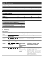
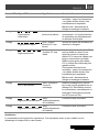
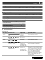
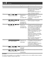
9. Operation
LED indicator
LED color
LED indication
Meaning
What to do?
Green
Solid
Power OK
Normal operation
Green
Slow blinking
Power
Saving Mode
Normal operation
Green
Intermittent blinking
Bypass Normal operation
Orange
Fast blinking
Warning: DC-
input voltage
too high
Check battery voltage and switch off
charger.
Orange
Slow blinking
Warning: DC-
input voltage
too low
Check if DC input voltage is too low
because of voltage drop across the
DC cables due to too long or too
narrow cables. Reduce the length of
the DC cables or use cables with a
larger gauge.
Loose or corroded connections:
Tighten the connections; burnt cables
must be corrected immediately.
Flat battery: Disconnect the load and
La pagina sta caricando ...
La pagina sta caricando ...
La pagina sta caricando ...
La pagina sta caricando ...
La pagina sta caricando ...
La pagina sta caricando ...
La pagina sta caricando ...
La pagina sta caricando ...
La pagina sta caricando ...
La pagina sta caricando ...
La pagina sta caricando ...
La pagina sta caricando ...
La pagina sta caricando ...
La pagina sta caricando ...
La pagina sta caricando ...
La pagina sta caricando ...
La pagina sta caricando ...
La pagina sta caricando ...
La pagina sta caricando ...
La pagina sta caricando ...
La pagina sta caricando ...
La pagina sta caricando ...
La pagina sta caricando ...
La pagina sta caricando ...
La pagina sta caricando ...
La pagina sta caricando ...
La pagina sta caricando ...
La pagina sta caricando ...
La pagina sta caricando ...
La pagina sta caricando ...
La pagina sta caricando ...
La pagina sta caricando ...
La pagina sta caricando ...
La pagina sta caricando ...
La pagina sta caricando ...
La pagina sta caricando ...
La pagina sta caricando ...
La pagina sta caricando ...
La pagina sta caricando ...
La pagina sta caricando ...
La pagina sta caricando ...
La pagina sta caricando ...
La pagina sta caricando ...
La pagina sta caricando ...
La pagina sta caricando ...
La pagina sta caricando ...
La pagina sta caricando ...
La pagina sta caricando ...
La pagina sta caricando ...
La pagina sta caricando ...
La pagina sta caricando ...
La pagina sta caricando ...
La pagina sta caricando ...
La pagina sta caricando ...
La pagina sta caricando ...
La pagina sta caricando ...
La pagina sta caricando ...
La pagina sta caricando ...
La pagina sta caricando ...
La pagina sta caricando ...
La pagina sta caricando ...
La pagina sta caricando ...
La pagina sta caricando ...
La pagina sta caricando ...
La pagina sta caricando ...
La pagina sta caricando ...
La pagina sta caricando ...
La pagina sta caricando ...
La pagina sta caricando ...
La pagina sta caricando ...
La pagina sta caricando ...
La pagina sta caricando ...
La pagina sta caricando ...
La pagina sta caricando ...
La pagina sta caricando ...
La pagina sta caricando ...
La pagina sta caricando ...
La pagina sta caricando ...
La pagina sta caricando ...
La pagina sta caricando ...
La pagina sta caricando ...
La pagina sta caricando ...
La pagina sta caricando ...
La pagina sta caricando ...
La pagina sta caricando ...
La pagina sta caricando ...
La pagina sta caricando ...
La pagina sta caricando ...
-
 1
1
-
 2
2
-
 3
3
-
 4
4
-
 5
5
-
 6
6
-
 7
7
-
 8
8
-
 9
9
-
 10
10
-
 11
11
-
 12
12
-
 13
13
-
 14
14
-
 15
15
-
 16
16
-
 17
17
-
 18
18
-
 19
19
-
 20
20
-
 21
21
-
 22
22
-
 23
23
-
 24
24
-
 25
25
-
 26
26
-
 27
27
-
 28
28
-
 29
29
-
 30
30
-
 31
31
-
 32
32
-
 33
33
-
 34
34
-
 35
35
-
 36
36
-
 37
37
-
 38
38
-
 39
39
-
 40
40
-
 41
41
-
 42
42
-
 43
43
-
 44
44
-
 45
45
-
 46
46
-
 47
47
-
 48
48
-
 49
49
-
 50
50
-
 51
51
-
 52
52
-
 53
53
-
 54
54
-
 55
55
-
 56
56
-
 57
57
-
 58
58
-
 59
59
-
 60
60
-
 61
61
-
 62
62
-
 63
63
-
 64
64
-
 65
65
-
 66
66
-
 67
67
-
 68
68
-
 69
69
-
 70
70
-
 71
71
-
 72
72
-
 73
73
-
 74
74
-
 75
75
-
 76
76
-
 77
77
-
 78
78
-
 79
79
-
 80
80
-
 81
81
-
 82
82
-
 83
83
-
 84
84
-
 85
85
-
 86
86
-
 87
87
-
 88
88
-
 89
89
-
 90
90
-
 91
91
-
 92
92
-
 93
93
-
 94
94
-
 95
95
-
 96
96
-
 97
97
-
 98
98
-
 99
99
-
 100
100
-
 101
101
-
 102
102
-
 103
103
-
 104
104
-
 105
105
-
 106
106
-
 107
107
-
 108
108


Mastervolt AC Master 24/2500 (230 V) Manuale utente
- Tipo
- Manuale utente
- Questo manuale è adatto anche per
in altre lingue
Documenti correlati
-
Mastervolt Digital AC 1x6A Manuale utente
-
-
Mastervolt AC Master 12/1500 (230 V) Manuale utente
-
-
-
-
-
Altri documenti
-
 Giandel PS-1000PDR 1000W Pure Sine Wave Inverter Manuale utente
-
Vetus Inverter type IV Manuale utente
-
Dometic MSI 2312T, MSI 2324T,MSI 3512T, MSI 3524T Istruzioni per l'uso
-
-
Hama 00047828 Manuale del proprietario
-
-
Victron energy Quattro 5k 8k 10k 15k 100-100A 230V (firmware xxxx4xx) Manuale del proprietario
-
 G-Tec Saturn Manuale utente
-
Trane WFE 2 Technical Manual
-
Vivanco 6-SOCKET MASTER-SLAVE MULTIPLE POWER OUTLET Manuale del proprietario

