Maytag MGD5707TQ1 Manuale del proprietario
- Tipo
- Manuale del proprietario

O
GAS DRYER
USE & CARE GUIDE
SECADORA A GAS
MANUAL DE USO Y CUIDADO
SECHEUSE A GAZ
GUIDE D'UTILISATION ET D'ENTRETIEN
Z
FOR QUESTI()NS ABOUT FEATURES, OPERATION/PERFORMANCE,
PARTS, ACCESSORIES OR SERVICE CALL: 1.800.688.9900
IN CANADA, CALL: 1.800.807.6777
VISIT ()UR WEBSITE AT WWW.MAYTAG.COM
IN CANADA, WWW.MAYTAG.CA
SI TIENE PREGUNTAS RESPECT() A LAS CARACTERiSTICA8,
FUNCIONAMIENT(), RENDIMIENTO, PARTES, ACCES()RI()S O
SERVICIO TECNICO, LLAME AL: 1.800.688.9900
O VISITE NUESTRO SITIO WEB EN
WWW.MAYTAG.COM
AU CANADA, POUR ASSISTANCE, INSTALLATION OU SERVICE,
COMPOSER LE : 1.800.807.6777
OU VISITEZ NOTRE SITE {NTERNET _,
WWW.MAYTAG.CA
W10088775

TABLE OF CONTENTS
DRYER SAFETY ..................................................................... 3
INSTALLATION INSTRUCTIONS ........................................ 5
TOOI.S AND PARTS .......................................................... 5
LOCATION REQUIREMENTS ........................................... 5
EI.ECTRICAL REQUIREMENTS ........................................... 7
GAS SUPPI Y REQUIREMENTS .......................................... 7
VENTING REQUIREMENTS ............................................... 8
PI.AN VENT SYSTEM ....................................................... 10
INSTAI.I. VENT SYSTEM ................................................... 11
INSTAH. I.EVEHNG EEGS ................................................ 11
MAKE GAS CON NECTION ............................................. 12
CON NECT VENT ............................................................. 12
LEVEl. [DRYER................................................................... 12
REVERSE DOOR SWING (OPTIONAl.) ............................ 13
COMPI.ETE INSTAl I ATION ............................................ 14
DRYER USE ......................................................................... 15
STARIING YOUR [DRYER ................................................ 15
DRYING RACK OPTION ................................................. 16
DRYER CARE ...................................................................... 16
C_LEANING THE [DRYER I.OCATION ............................... 16
CI.EANING THE I.INT SCREEN ........................................ 16
CLEANING THE DRYER INTERIOR ................................. 17
REMOVING ACCUMUI.AFED [.INT ................................ 17
VACATION AND MOVING CARE .................................. 17
CHANGING THE DRUM lIGHT ..................................... 17
TROUBLESHOOTING ........................................................ 18
ASSISTANCE OR SERVICE .................................................. 20
WARRANTY ....................................................................... 21
P
INDICE
SEGURIDAD DE LA SECADORA ....................................... 22
INSTRUCCIONES DE INSTALACION ............................... 24
HERRAMIENTAS Y PIEZAS .............................................. 24
REQUISITOS [DE UBICACION ....................................... 24
REC,)UISITOS EI.ECTRICOS .............................................. 26
REQUISITOS DEI. SUMINISTRO DE GAS ....................... 27
REC,)UISITOS [DEVENTII ACION ..................................... 28
PI.ANIFICACId_)N DE[ SISTEMA DE VENTILACI('_)N ....... 29
INSTAI.ACION [])El. SISI EMA DE VENTII.ACION ........... 31
INSIAI.ACION DE LAS PATAS NIVELADORAS .............. 31
CONEXI('_)N DEI. SUMINISTRO DE GAS ........................ 31
CONEXION DEI. DUCTO [DE ESCAPE ............................ 32
NIVEI.ACION DE EA SECADORA ................................... 32
COMO INVERTIR ELCIERRE DE EA
PUERTA (OPCIONAI) ..................................................... 33
COMPLETE [A INSTAEACION ........................................ 34
USO DE LA SECADORA .................................................... 35
PUESTA EN MARCHA DE SU SECADC)RA ..................... 35
OPCION ES-IANTE DE SECADO ..................................... 36
CUIDADO DE LA SECADORA .......................................... 37
I IMPIEZA DEI. IUGAR DONDE ESTI_ I.A SECADORA... 37
LIMPIEZA DEI. FILTRO DE PE[ USA ................................ 37
I IMPIEZA [DE[ INTERIOR [DELA SECADORA ................ 38
El IMINACI(_)N DE PEI.USA ACUMU[ ADA .................... 38
CUIDADO PARA I.AS VACACIONES Y [.A MUDANZA. 38
CAMBIO DE LA EUZ DEE TAMBOR ............................... 38
SOLUClON DE PROBLEMAS ............................................ 39
AYUDA O SERVICIO Tf_CNICO ........................................ 41
GARANTIA ........................................................................ 42
TABLE DES MATIERES
Sf_CURITI!DE LA Sf_CHEUSE .............................................. 43
INSTRUCTIONS D'INSTALLATION .................................. 45
OUTI[ I.AGE ET PIECES NECESSAIRES ............................. 45
EXIGENCES D'INSTAI.LATION ........................................ 45
SPECI FICATIONS 1_[ECTRIQU ES..................................... 47
SPECIFICATIONS DE E'AI.IMENTATION EN GAZ .......... 48
EXIGENCES CONCERNANT IJEVACUATION ................ 49
PI.ANIFICATION DU SYSTEME D'EVACUATION ........... 50
INSIAEI.ATION DU SYSTEME D'EVACUATION ............ 52
INSTAI.I.ATION [DES PIEDS DE NIVELEEMENT. .............. 52
RACCORDEMENT AU GAZ ............................................ 52
RACCORDEMENT DU CONDUIT D'EVACUATION ...... 53
MISE _, NIVEAU [DE I.A SECHEUSE ................................. 53
INVERSION DU SENS D'OUVERTURE DE IA
PORTE (FACUI.TATIF) ..................................................... 54
ACHEVER I.'INSTAI.I.ATION ........................................... 55
UTILISATION DE LA SECHEUSE ....................................... 56
MISE EN MARCHE DE LA SECHEUSE ............................. 56
OPTION GRIHE DE SECHAGE ....................................... 57
ENTRETIEN DE LA SI_CHEUSE ........................................... 58
NETTOYA¢;E [DE UEMPI.ACEMENT [DE I.A SECHEUSE... ,_8
NETTOYAGE DU FILTRE ,'_ CHARPIE ............................. ,_8
NETTOYACE [DE [ 'INTERIEUR DE IA SECHEUSE ........... 58
COMMENT ENI.EVER I.A CHARPIE ACCUMUI.EE .......... 59
PRECAUTIONS _, PRENDRE POUR I.ES VACANCES ET
AVANT UN DEMENAGEMENT ....................................... 59
CHANGEMENT [DE I'AMPOUI E DU TAMBOUR .......... 59
Df_PANNAGE ..................................................................... 60
ASSISTANCE OU SERVICE ................................................. 62
GARANTIE ......................................................................... 63
2

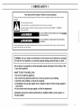
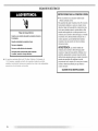
DRYER SAFETY
Your safety and the safety of others are very important.
We have provided many important safety messages in this manual and on your appliance. Always read and obey all safety
messages.
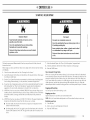
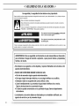
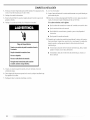
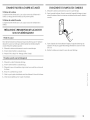
This is the safety alert symbol.
This symbol alerts you to potential hazards that can kill or hurt you and others.
All safety messages will follow the safety alert symbol and either the word "DANGER" or "WARNING."
These words mean:
You can be killed or seriously injured if you don't immediately
follow instructions.
You can be killed or seriously injured if you don't follow
instructions.
All safety messages will tell you what the potential hazard is, tell you how to reduce the chance of injury, and tell you what can
happen if the instructions are not followed.
I
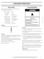
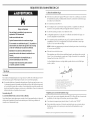
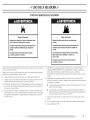
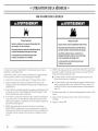
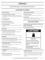
I WARNING: For your safety, the information in this manual must be followed to minimize
the risk of fire or explosion, or to prevent property damage, personal injury, or death.
- Do not store or use gasoline or other flammable vapors and liquids in the vicinity of this
or any other appliance.
- WHAT TO DO IF YOU SMELL GAS:
• Do not try to light any appliance.
• Do not touch any electrical switch; do not use any phone in your building.
• Clear the room, building, or area of all occupants.
• Immediately call your gas supplier from a neighbor's phone. Follow the gas supplier's
instructions.
• If you cannot reach your gas supplier, call the fire department.
- Installation and service must be performed by a qualified installer, service agency, or
the gas supplier.

In the State of Massachusetts, the following installation instructions apply:
[] Installations and repairs must be performed by a qualified or licensed contractor, plumber, or gasfitter qualified or licensed by
the State of Massachusetts.
[] If using a ball valve, it shall be a T-handle type.
[] A flexible gas connector, when used, must not exceed 3 feet.
iMPORTANT SAFETY INSTRUCTIONS
WARNING: To reduce the risk of fire, electric shock, or injury to persons when using the dryer, follow basic precautions,
including the following:
[] Read all instructions before using the dryer.
[] Do not place items exposed to cooking oils in your dryer.
Items contaminated with cooking oils may contribute to
a chemical reaction that could cause a load to catch fire.
[] Do not dry articles that have been previously cleaned in,
washed in, soaked in, or spotted with gasoline, dry-
cleaning solvents, or other flammable or explosive
substances as they give off vapors that could ignite or
explode.
[] Do not allow children to play on or in the dryer. Close
supervision of children is necessary when the dryer is
used near children.
[] Before the dryer is removed from service or discarded,
remove the door to the drying compartment.
[] Do not reach into the dryer if the drum is moving.
[] Do not install or store the dryer where it will be exposed
to the weather.
[] Do not tamper with controls.
[] Do not repair or replace any part of the dryer or attempt
any servicing unless specifically recommended in this
Use and Care Guide or in published user-repair
instructions that you understand and have the skills to
carry out.
[] Do not use fabric softeners or products to eliminate static
unless recommended by the manufacturer of the fabric
softener or product.
[] Do not use heat to dry articles containing foam rubber or
similarly textured rubber-like materials.
[] Clean lint screen before or after each load.
! Keep area around the exhaust opening and adjacent
surrounding areas free from the accumulation of lint, dust,
and dirt.
[] The interior of the dryer and exhaust vent should be
cleaned periodically by qualified service personnel.
[] See installation instructions for grounding requirements.
SAVE THESE iNSTRUCTiONS
iMPORTANT: The gas installation must conform with local codes, or in the absence of local codes, with the National Fuel Gas
Code, ANSI Z223.1/NFPA 54 or the Canadian Natural Gas and Propane Installation Code, CSA B149.1.
The dryer must be electrically grounded in accordance with local codes, or in the absence of local codes, with the National
Electrical Code, ANSI/NFPA 70 or Canadian Electrical Code, CSA C22.1.
4

INSTALLATION INSTRUCTIONS
TOOLS AND PARTS
Gather the required tools and parts before starting installation. Read and follow the
instructions provided with ally tools listed here.
8" or 10" pipe wrench
8" or 10" adjustable
wrench (for gas
connections/
Flat-blade screwdriver
Adjustable wrench that
opens to 1" (2.5 cm) or
hex-head socket wrench
(for adjusting dryer feet)
_/4"nut driver or socket
wrench (recommended)
• level
• Knife
• Vent clamps
• Pipe-joint compound
resistant to [P gas
• Caulking gun and
compound (for installing
new exhaust vent)
• Pliers
• Tape measure
Parts supplied:
Remove parts package from dryer drum. Check that all parts were included.
4 lew_ling legs
Parts needed:
Check local codes and consult gas supplier. Check existing gas supply, electrical supply and
venting, and read "Electrical Requirements," "Gas Supply Requirements" and "Venting
Requirements" before purchasing parts.
Mobile home installations require special parts (listed following) that may be ordered by
calling the dealer from whom you purchased your dryer. For further information, please refer
to the "Assistance or Service" section of this manual.
• Mobile Home Installation Kit. Ask for Part Number 346764.
• Metal exhaust system hardware.
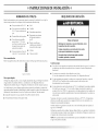
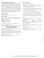
LOCATION REQUIREMENTS
Explosion Hazard
Keep flammable materials and vapors, such as
gasoline, away from dryer.
Place dryer at least 18 inches (46 cm) above the floor
for a garage installation.
Failure to do so can result in death, explosion, or fire.
You will need
• A location that allows for proper exhaust installation. A gas dryer must be exhausted to
the outdoors. See "Vc'nting Requirements."
• A grounded electrical outlet located within 2 ft (61 cm) of either side of the dryen See
"Electrical Requirements."
• A sturdy floor to support the dryer and a total weight (dryer and load) of 200 Ibs (90.7 kg).
The combined weight of a companion appliance should also be considered.
• A level floor with a maximum slope of 1" (2.5 cm) under entire dryer. ([f slope is greater
than 1" [2.5 cml, install Extended Dryer Feet kit, Part No. 279810.) Clothes may not
tumble properly and models with automatic sensor cycles may not operate correctly if
dryer is not level.
Do not operate your dryer at temperatures below 45°F (7°C). At lower temperatures, the dryer
might not shut off at the end of an automatic cycle. Drying times can be extended.
The dryer must not be installed or stored in an area where it will be exposed to water and/or
weather.
Check code requirements. Some codes limit, or do not permit, installation of the dryer in
garages, closets, mobile homes or sleeping quarters. Contact your local building inspector.
NOTE: No other fuel-burning appliance can be installed in the same closet as a dryer.
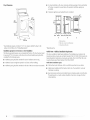
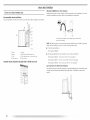
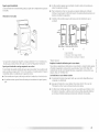
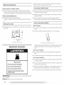
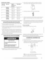
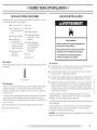
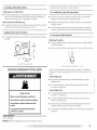
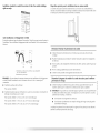
Installation Clearances
The location must be large enough to allow the dryer door to open fully.
I

Dryer Dimensions
43%"
(110 cm)
(70.5 cm)
223/4"
(57.8 cm)
*Most installations require a minimum 5" (12.7 cm) clearance behind the dryer for the
exhaust vent with elbow. See "Venting Requirements."
Installation spacing for recessed area or closet installation
The following spacing dimensions are recommended for this dryer, This dryer has been tested
for spacing of 0" (0 cm) clearance on the sides and rear. Recommended spacing should be
considered for the following reasons:
• Additional spacing should be considered for ease of installation and servicing.
• Additional clearances might be required for wall, door and floor moldings.
• Additional spacing should be considered on all sides of the dryer to reduce noise transfer.
• For closet installation, with a door, minimum ventilation openings in the top and bottom
of the door are required. [ ouvered doors with equivalent ventilation openings are
acceptable.
• Companion appliance spacing should also be considered.
_" 3"*
(7.6cm)
(7.6cm)
C
B. Side view - closet or confined area
C. Closet door with vents
*Required spacing
Mobile Home - Additional Installation Requirements
This dryer is suitable for mobile home installations. The installation must conform to the
Manufactured Home Construction and Safety Standard, Title 24 CFR, Part 3280 (formerly the
Federal Standard for Mobile Home Construction and Safety, Title 24, HUD Part 280) or the
Canadian Manufactured Home Standard, CAN/CSA-Z240 MH.
Mobile home installations require:
• Metal exhaust system hardware, which is aw_ilable for purchase from your dealer.
• Mobile Home Installation Kit Part Number 346764. See 'qools and Parts" section for
information on ordering.
• Special provisions must be made in mobile homes to introduce outside air into the dryer.
The opening (such as a nearby window) should be at least twice as large as the dryer
exhaust opening.
6

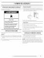
ELECTRICAL REQU IREMENTS
Electrical Shock Hazard
Plug into a grounded 3 prong outlet.
Do not remove ground prong.
Do not use an adapter.
Do not use an extension cord.
Failure to follow these instructions can result in death,
fire_ or electrical shock.
120 Volt, 60 Hz., AC only, 15- or 20-amp fused electrical supply is required. A time-delay
fuse or circuit breaker is recommended. [t is also recommended that a separate circuit
serving only this dryer be provided.
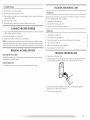
GROUNDING iNSTRUCTiONS
• For a grounded, cord-connected dryer:
This dryer must be grounded. In the event of malfunction or
breakdown, grounding will reduce the risk of electric shock
by providing a path of least resistance for electric current.
This dryer is equipped with a cord having an equipment-
grounding conductor and a grounding plug. The plug must
be plugged into an appropriate outlet that is properly
installed and grounded in accordance with all local codes
and ordinances.
WARNING: Improper connection of the equipment-
grounding conductor can result in a risk of electric shock.
Check with a qualified electrician or service representative
or personnel if you are in doubt as to whether the dryer is
properly grounded. Do not modify the plug provided with the
dryer: if it will not fit the outlet, have a proper outlet installed
by a qualified electrician.
SAVE THESE INSTRUCTIONS
GAS SUPPLY REQUIREMENTS
Explosion Hazard
Use a new CSA international approved gas supply line.
install a shut-off valve.
Securely tighten all gas connections.
if connected to LP, have a qualified person make sure
gas pressure does not exceed 13" (33 cm) water
column.
Examples of a qualified person include:
licensed heating personnel,
authorized gas company personnel, and
authorized service personnel.
Failure to do so can result in death, explosion, or fire.
Gas Type
Natural Gas:
This dryer is equipped for use with Natural gas. [t is design-certified by CSA International for
I.P/propane or butane/gases with appropriate conversion.
• Your dryer must have the correct burner for the type of gas in your home. Burner
information is located on the rating plate in the door well of your dryer. Ifthis information
does not agree with the type of gas available, contact your dealer or call the phone
numbers referenced on the front page of this manual.
[P gas conversion:
Conversion must be made by a qualified technician.
No attempt shall be made to convert the appliance from the gas specified on the model/serial
rating plate for use with a different gas without consulting your gas company.
I

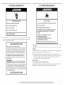
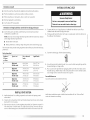
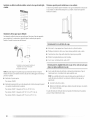
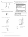
Gas Supply Line:
• Must include 1/8" NPT minimum plugged tapping accessible for test gauge connection,
immediately upstream of the gas connection to the dryer. See illustration.
• 1/2" IPS pipe is recommended.
• 3/8"approved aluminum or copper tubing is acceptable for lengths under 20 ff (6.1 m) if
local codes and gas supplier permit.
• If you are using Natural gas, do not use copper tubing.
• kengths over 20 ff (6.1 m) should use larger tubing and a different size adapter fitting.
• If your dryer has been converted to use LP gas, 3/8" I.P compatible copper tubing can be
used. If the total length of the supply line is more than 20 ft (6.1 m), use larger pipe.
NOTE: Pipe-joint compounds that resist the action of IP gas must be used. Do not use
TEFLON '_tape.
• Must include a shutoff valve:
In the U.S.A.:
An individual manual shutoff w_lve must be installed within six (6) feet (1.8 m) of the dryer
in accordance with the National Fuel Gas Code, ANSI Z223.1.
In Canada:
An individual manual shutoff valve must be installed in accordance with the B149.1,
Natural Gas and Propane Installation Code. [t is recommended that an individual manual
shutoff valve be installed within six (6) feet (1.8 m) of the dryer.
The location should be easy to reach for opening and closing.
A C E
B D
A. _" flexible gas connector
B. _" pipe to flare adapter fitting
C. _" NP I minimum plugged tapping
D. _//' NPT gas supply line
E. Gas shutoff valve
Gas supply connection requirements
• Use an elbow and a %" flare x %" NPT adapter fitting between the flexible gas connector
and the dryer gas pipe, as needed to avoid kinking.
• Use only pipe-joint compound. Do not use FEFI.ON _÷*tape.
• [his dryer must be connected to the gas supply line with a listed flexible gas connector
that complies with the standard for connectors for gas appliances, ANSI Z21.24 or
CSA 6.10.
_-f_TEFLON is a registeued trademark of E.I. Du Pont De Nemours and Company.
Burner Input Requirements:
Elevations above 10,000 ft (3,048 m):
• When instal led above 10,000 ft (3,048 m) a 4% reduction of the burner Btu rating shown
on the model/serial number plate is required for each ,000 ft (305 m) increase in
elevation.
Gas supply pressure testing
• The dryer must be disconnected from the gas supply piping system during pressure testing
at pressures greater than % psi.
Dryer Gas Pipe
• The gas pipe that comes out through the rear of your dryer has a %" male pipe thread.
A
(23.5cm)
A. a_,,NPT dryer pipe
VENTI NG REQU I REMENTS
Fire Hazard
Use a heavy metal vent.
Do not use a plastic vent.
Do not use a metal foil vent.
Failure to follow these instructions can result in death
or fire.
WARNING: lb reduce the risk of fire, this dryer MUST BE EXHAUSTED OUTDOORS.
IMPORTANT: Observe all governing codes and ordinances.
[he dryer exhaust must not be connected into any gas vent, chimney, wall, ceiling or a
concealed space of a building.
8

If using an existing vent system
• Clean lint from the entire length of the system and make sure exhaust hood is not plugged
with lint.
• Replace any plastic or metal foil vent with rigid or flexible heavy metal vent.
• Review Vent system chart. Modify existing vent system if necessary to achieve the best
drying performance.
If this is a new vent system
Exhaust
Vent material
• Use a heavy metal vent. Do not use plastic or metal foil vent.
• 4" (10.2 cm) heavy metal exhaust vent and clamps must be used.
4" ( 10.2 cm) heavy metal _'xhaust vent
Vent products can be purchased from your dealer or by calling Maytag Services. For more
information, see the "Assistance or Service" section of this manual.
Rigid metal vent
• For best drying performance, rigid metal vents are recommended.
• Rigid metal vent is recommended to avoid crushing and kinking.
Flexible metal vent
• Flexible metal vents are acceptable only if accessible for cleaning.
• Flexible metal vent must be fully extended and supported when the dryer is in its final
location.
• Remove excess flexible metal vent to avoid sagging and kinking that may result in
reduced airflow and i)oor i)erformance. •
• Do not install flexible metal vent in enclosed walls, ceilings or floors.
Elbows
45 ° elbows provide better airflow than 90 ° elbows.
Good Better
Clamps
• Use clamps to seal all joints.
• Exhaust vent must not be connected or secured with screws or other fastening devices
that extend into the interior of the duct. Do not use duct tape.
Clamp
Recommended hood styles are shown here.
B
(10.2 cm)
A. Louvemd hood style"
B.Box hood style"
The angled hood style (shown here) is acceptable.
An exhaust hood should cap the vent to kee I) rodents and insects from entering the home.
Exhaust hood must be at least 12" (30.5 cm) from the ground or any object that may be in
the path of the exhaust (such as flowers, rocks or hushes, snow line, etc./.
Do not use an exhaust hood with a magnetic latch.
Improper venting can cause moisture and lint to collect
indoors, which may result in:
[] Moisture damage to woodwork, furniture, paint, wallpaper,
carpets, etc.
[] Housecleaning problems and health problems.

PLAN VENT SYSTEM
Choose your exhaust installation type
Recommended exhaust installations
Typical installations vent tile dryer from the rear of tile dryer. Other installations are possible.
A ¸
B
.........i..............................F
A. Dryer
B. Elbow
C. Wall
D. Fxhaust hood
E. Clamps
£ Rigid metal or flexible metal vent
G. V_'nt length necessary to connect elbows
H. fxhaust outlet
Standard exhaust installation with rigid metal or flexible metal vent
Alternate installations for close clearances
Venting systems come in many w_rieties. Select the type best for your installation. |wo close-
clearance installations are shown. Refer to the manufacturer's instructions.
[.........
A B
A. Over-the-top installation (aho available with one offset elbow)
B.Periscope installation
NOTE: The following kits for close clearance alternate installations are available for purchase.
Please see the "Assistance or Service" section of this manual to order.
• Over-the-lbp Installation:
Part Number 4396028
• Periscope Installation (For use with dryer vent to wall vent mismatch):
Part Number 4396037 - 0" (0 cm) to 18" (45.72 cm) mismatch
Part Number 4396011 - 18" (45.72 cm) to 29" (73.66 cm) mismatch
Part Number 4396014- 29" (73.66 cm) to 50" (127 cm) mismatch
Special provisions for mobile home installations
The exhaust vent must be securely fastened to a noncombustible portion of the mobile home
structure and must not terminate beneath the mobile home. Terminate the exhaust vent
outside.
/

Determine vent path
• Select the route that will provide the straightest and most direct path outdoors.
• Plan the installation to use the fewest number of elbows and turns.
• When using elbows or making turns, allow as much room as possible.
• Bend vent gradually to avoid kinking.
• Use the fewest 90 ° turns possible.
Determine vent length and elbows needed for best drying performance
• Use the Vent system chart below to determine type of vent material and hood
combinations acceptable to use.
NOTE: Do not use vent runs longer than those specified in the Vent system chart. Exhaust
systems longer than those specified will:
• Shorten the life of the dryer.
• Reduce performance, resulting in longer drying times and increased energy usage.
The Vent system chart provides venting requirements that will help to achieve the best drying
performance.
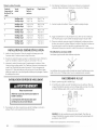
Vent system chart
90 ° turns hoods
or elbows
0 Rigid metal 64 ft 120 m) 58 ft (17.7 m)
Flexible metal 36 ft (11 r'n) 28 ft (8.5 r'n)
1 Rigid metal 54 ft (16.,5 m) 48 ft (14.6 m)
Flexible metal 31 ft 19.4 m) 23 ft 17 m)
2 Rigid metal 44 ft (13.4 m/ 38 ft (11.6 m/
Flexible metal 27 ft (8.2 m/ 19 ft 15.8 m/
3 Rigid metal 35 ft (10.7 m) 29 ft (8.8 m)
Flexible metal 25 ft (7.6 m) 17 ft (5.2 m)
4 Rigid metal 27 ft (8.2 m) 21 ft (6.4 m)
Flexible metal 23 ft (7 m) 15 ft (4.6 m)
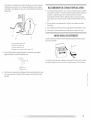
INSTALL VENT SYSTEM
1. Install exhaust hood. Use caulking compound to seal exterior wall opening around
exhaust hood.
2. Connect vent to exhaust hood. Vent must fit inside exhaust hood. Secure vent to exhaust
hood with 4" (10.2 cm) clamp.
3. Run vent to dryer location. Use the straightest path possible. See "Determine vent path" in
"Plan Vent System." Avoid 90° turns. Use clamps to seal all joints. Do not use duct tape,
screws or other fastening devices that extend into the interior of the vent to secure vent.
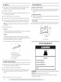
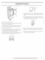
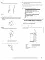
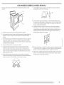
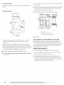
INSTALL LEVELING LEGS
Excessive Weight Hazard
Use two or more people to move and install dryer.
Failure to do so can result in back or other injury.
1. [b protect the floor, use a large flat piece of cardboard from the dryer carton. Place
cardboard under the entire back edge of the dryer.
2. Firmly grasp the body of the dryer (not the top or console panel). Gently lay the dryer on
the cardboard. See illustration.
Examine the leveling legs. Find the diamond marking.
4. Screw the legs into the leg holes by hand. Use a wrench to finish turning the legs until the
diamond marking is no longer visible.
5. Place a carton corner post from dryer packaging under each of the 2 dryer back corners.
Stand the dryer up. Slide the dryer on the corner posts until it is close to its final location.
Leave enough room to connect the exhaust vent or gas line.
For mobile home use
Gas dryers must be securely fastened to the floor.
Mobile home installations require a Mobile Home Installation Kit. See "[bols and Parts"
section for information on ordering.
I

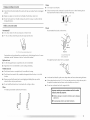
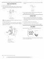
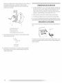
MAKE GAS CONNECTION
1. Remove the red cap from the gas pipe.
2. Using a wrench to tighten, connect the gas supply to the dryer. Use pipe-joint compound
on the threads of all non-flared male fittings. If flexible metal tubing is used, be sure there
are no kinks.
A.................................._ _ .......................B
A. Flared male thread
B. Non-flared male thread
NOTE: For [.P gas connections, you must use pipe-joint compound resistant to the action
of [P gas. Do not use ]EFi.ON _tape.
A combination of pipe fittings must be used to connect the dryer to the existing gas line.
Shown is a recommended connection. Your connection may be different, according to the
supply line type, size, and location.
I
A
A. _" flexible gas connector
B. _" dryer pipe
C. _" to _" pipe elbow
D. _" pipe-to-flare adapter fitting
3. Open the shutoff valve in the supply line. [he valve is open when the handle is parallel to
the gas pipe.
A. Closed valve
B.Open valve
4. lest all connections by brushing on an approved noncorrosive leak-detection solution.
Bubbles will show a leak. Correct any leak found.
CONNECT VENT
1. Using a 4" (10.2 cm) clamp, connect vent to exhaust outlet in dryer. If connecting to
existing vent, make sure the vent is clean. The dryer vent must fit over the dryer exhaust
outlet and inside the exhaust hood. Check that the vent is secured to exhaust hood with a
4" (10.2 cm) clamp.
2. Move dryer into its final location. Do not crush or kink vent.
3. (On gas models) Check that there are no kinks in the flexible gas line.
4. Once the exhaust vent connection is made, remove the corner posts and cardboard.
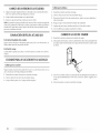
LEVEL DRYER
Check the levelness of the dryer. Check levelness first side to side, then front to back.
If the dryer is not level, prop up the dryer using a wood block. Use a wrench to adjust the legs
up or down and check again for levelness.
t,_¢,TEFLON is a registered trademalk of E.I. Du Pont De Nemours and Company.
12

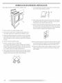
REVERSE DOOR SWING (OPTIONAL)
You can change your door swing from a right-side opening to a left-side opening, if desired. 7. Attach door hinges to dryer door so that tile larger hole is at the bottom of the hinge.
1. Place towel (A) on top of dryer to protect surface.
2. Open dryer door. Remove bottom screws from cabinet side of hinges (D). loosen (do not
remove) top screws from cabinet side of hinges.
3. I.ifl door until top screws in cabinet are in large part of hinge slot. Pull door forward off
screws. Set door (handle side up) on top of dryer. Remove top screws from cabinet.
4. Remove screws attaching hinges to door.
5. Remove screws at top, bottom and side of door (4 screws). Holding door over towel on
dryer, grasp skies of outer door anti gently lift to separate it from inner door. Do not pry
apart with putty knife. Do not pull on door seal or plastic door catches.
6. Be certain to keep cardboard spacer centered between doors. Reattach outer door panel
to inner door panel so handle is on the side where hinges were just removed.
8. Remove door strike (E) from cabinet. Use a small, flat-blade screwdriver to gently remove
4 hinge hole plugs (F) on left side of cabinet, insert plugs into hinge holes on right side of
cabinet.
9. insert screws into bottom holes on left side of cabinet, lighten screws halfway. Position
door so large end of door hinge slot is over screws. Slide door up so screws are in bottom
of slots. Tighten screws, insert and tighten top screws in hinges.
10. Remove door strike plug (B). Insert the door strike you removed in Step 8 into hole and
secure with screw, insert door strike plug into original door strike hole and secure with
screw.
11. Close door and check that door strike aligns with door catch (C). [f it is needed, slide door
catch left or right within slot to adjust alignment.

COMPLETE INSTALLATION
1. Check that all parts are now installed. If there is an extra part, go back through the steps to
see which step was skipped.
2. Check that you have all of your tools.
3. Check the dryer's final location. Be sure the vent is not crushed or kinked.
4. Check that the dryer is level. See "level Dryer."
Electrical Shock Hazard
Plug into a grounded 3 prong outlet.
Do not remove ground prong.
Do not use an adapter.
Do not use an extension cord,
Failure to follow these instructions can result in death,
fire, or electrical shock.
6. Remove any protective film on the console and any tape remaining on the dryer.
7. Dispose of/recycle all packaging materials.
8. Read "Dryer Use."
9. Wipe the dryer drum interior thoroughly with a damp cloth to remove any dust.
10. Select a Timed Dry heated cycle, and start the dryer. Do not select the Air Only
]emperature setting.
If the dryer will not start, check the following:
• Dryer is plugged into a grounded 3 prong outlet.
• Electrical supply is connected.
• Household fuse is intact and tight, or circuit breaker has not tripped.
• Dryer door is closed.
11. When the dryer has been running for 5 minutes, open the dryer door and feel for heat. [f
you feel heat, cancel cycle and close door. If you do not feel heat, turn off the dryer and
check that the gas supply line shutoff valve is open.
• If the gas supply line shutoff valve is closed, open it, then repeat the 5-minute test as
outlined above.
• If the gas supply line shutoff valve is open, contact a qualified technician.
5. Plug into a grounded 3 prong outlet. Turn on power.
14

DRYER USE
STARTING YOUR DRYER
Explosion Hazard
Keep flammable materials and vapors, such as
gasoline, away from dryer,
Do not dry anything that has ever had anything
flammable on it (even after washing).
Failure to follow these instructions can result in death,
explosion, or fire.
Fire Hazard
No washer can completely remove oil.
Do not dry anything that has ever had any type of oil on
it (including cooking oils).
items containing foam, rubber, or plastic must be dried
on a clothesline or by using an Air Cycle.
Failure to follow these instructions can result in death
or fire.
iI!"I
This book covers several different models. Your dryer may not have all of the cycles and
features described.
Before using your dryer, wipe the dryer drum with a damp cloth to remove dust from storing
and shipping.
1. Clean lint screen before each load. See "Cleaning the Lint Screen."
2. I.oad clothes loosely into the dryer and close the door. Do not pack the dryer. Allow space
for clothes to tumble freely.
3. Ibm the Cycle Control knob to the recommended cycle for the type of load being dried,
Use the Energy Preferred setting (*) to dry most heavy to medium-weight fabrics.
4. If your dryer has a lemperature selector, set it to the recommended setting for the type of
fabric being dried. See "Dryer Cycle Descriptions" (separate sheet) for temperature
suggestions. On some models, temperature is included in the cycle selections.
5. (OPTIONAl.) Your dryer may have a WRINKI.E PREVENT feature selector. When you are
unable to remove a load from the dryer as soon as it stops, wrinkles can form. This feature
periodically tumbles, rearranges and fluffs the load without heat to help smooth out
wrinkles.
6. (OPTIONAL) Your dryer may have an END OF CYCLE SIGNAL. The signal is helpful when
drying items that should be removed from the dryer as soon as it stops.
• On some models, the volume of the End of Cycle signal can be adjusted, Turn the
selector to the desired volume.
• On other models, tile End of Cycle signal is part of tile Start button and is selectable.
Turn the START button to ON or OFF. The signal will sound only if the selector is set
to On.
7. Select the desired Option. See "Dryer Cycle Descriptions" (separate sheet).
8. If desired, add fabric softener sheet. Follow instructions on the package.
9. Push the START button.
How Automatic Drying Works
When you are using the Auto Moisture Sensing Cycle, the dryness of the load is determined
by two metal strips/sensors) located on the inside of the dryer. The metal strips help "feel" the
amount of moisture left in the clothes as they pass. When moisture is left in the clothes, the
Cycle Control knob will not advance. As clothes begin to dry, the amount of water left in the
clothes decreases, and the timer advances through the remainder of the cycle. When the
selected dryness level is reached, the dryer goes into a cool down period of up to 10 minutes.
Stopping and Restarting
You can stop your dryer anytime during a cycle.
Stopping your dryer
Open the dryer door or turn the Cycle Control knob to OFF.
NOTE: The Cycle Control knob should point to an Off area when the dryer is not in use.
Restarting your dryer
1. Close the door.
2. Select a new cycle and temperature (if desired).
3. Push the START button.

DRYING RACK OPTION
Use the Drying Rack to dry items such as sweaters and pillows without tumbling. The drum
turns, but the rack does not move.
[f your model does not have a drying rack, you may be able to purchase one for your model. [b
find out whether your model allows drying rack usage and for information on ordering, please
refer to the front page of the manual or contact the dealer from whom you purchase(] your dryer.
NOTE: The rack must be removed for normal tumbling. Do not use the automatic cycle with
the drying rack.
To use the drying rack
1. Place drying rack in dryer.
Style 1: Your drying rack has front legs. Slide rear pegs into the dimples on the back wall
of the dryer. I.ower the front legs to rest on the dryer opening.
Style 2: Your drying rack does not have front legs. Do not remove the lint screen. Slide
drying rack over the bottom of the dryer door opening. Push down to secure rack on
frame.
2. Put wet items on top) of rack, leaving space between items. Do not allow items to hang
over the edge of the rack. Close the door.
3. Select a timed drying cycle and temperature, or an air cycle. Items containing foam,
rubber, or plastic must be dried on a clothesline or by using an air cycle. Refer to the
following table.
4. Start the dryer. Reset cycle to complete drying, if needed.
Rack Dry Cycle Temp Time
Washable wool items (block to shape, lay Timed Drying low 60 min.
flat on rack)
Stuffed toys/pillows ]cotton or polyester Timed Drying low 60 min.
filled)
Stuffed toys/pillows Air (no heat) N/A 90 min.
Foam rubber filled
¢+ DRYER CARE ¢+
CLEANING THE DRYER LOCATION
Kee l) dryer area clear and free from items that would obstruct the flow of combustion and
ventilation air.
Explosion Hazard
Keep flammable materials and vapors, such as
gasoline, away from dryer.
Place dryer at least 18 inches (46 cm) above the floor
for a garage installation.
Failure to do so can result in death, explosion, or fire.
CLEANING THE LINT SCREEN
Clean lint screen before each load. A screen blocked by lint can increase drying time.
IMPORTANT:
• Do not run the dryer with the lint screen loose, damaged, blocked or missing. Doing so
can cause overheating and damage to both the dryer and fabrics.
• If lint falls off the screen into the dryer during removal, check the exhaust hood and
remove the lint.
Every Load Cleaning
1. The lint screen is located on top of the dryer, Pull the lint screen toward you. Roll lint off
the screen with your fingers. Do not rinse or wash screen to remove lint. Wet lint is hard
to remove.
2. Push the lint screen firmly back into place,
16

As Needed Cleaning
1. Roll lint off the screen with your fingers.
2. Wet both sides of lint screen with hot water.
3. Wet a nylon brush with hot water and liquid detergent. Scrub lint screen with the brush to
remove residue buildup.
4. Rinse screen with hot water.
5. Thoroughly dry lint screen with a clean towel. Replace screen in dryer.
CLEANING THE DRYER INTERIOR
1. Apply a liquid, nonflammable household cleaner to the stained area of the drum and rub
with a soft cloth until stain is removed.
2. Wipe drum thoroughly with a damp cloth.
3. Tumble a load of clean cloths or towels to dry the drum.
NOTE: Garments that contain unstable dyes, such as denim blue jeans or brightly colored
cotton items, may discolor the dryer interior. These stains are not harmful to your dryer and
will not stain future loads of clothes. Dry unstable dye items inside-out to avoid dye transfer.
REMOVING ACCUMULATED LINT
From Inside the Dryer Cabinet
lint should be removed every 2 years, or more often, depending on dryer usage. Cleaning
should be done by a qualified person.
From the Exhaust Vent
lint should be removed every 2 years, or more often, depending on dryer usage.
VACATION AND MOVING CARE
Vacation care
Oi)erate your dryer only when you are at home. If you will be on vacation or not using your
dryer for an extended period of time, you should:
1. Unplug dryer or disconnect power.
2. Close shutoff valve in gas supply line.
3. Clean lint screen. See "Cleaning the lint Screen."
Moving care
1. Unplug the power supply cord.
2. Close shutoff valve in gas supply line.
3. Disconnect gas supply line pipe and remove fittings attached to dryer pipe.
4. Cap the open fuel supply line.
5. Make sure leveling legs are secure in dryer base.
6. Use masking tape to secure dryer door.
CHANGING THE DRUM LIGHT
1. Unplug dryer or disconnect power.
2. Open the dryer door. I.ocate the light bulb cover on the back wall of the dryer. Remove
the screw located in the lower right-hand corner of the cover. Remove the cover.
3. Turn bulb counterclockwise. Replace the bulb with a 1O-watt appliance bulb only.
Replace the cover and secure with the screw.
4. Plug in dryer or reconnect power.
I

TROUBLESHOOTING
First try the solutions suggested here and possibly avoid the cost of a service call...
DRYER OPERATION
Dryer will not run
Has a household fuse blown, or has a circuit breaker tripped?
Electric dryers use 2 household fuses or circuit breakers. The drum may be turning, but
you may not have heat. Replace the fuse or reset the circuit breaker. If the problem
continues, call an electrician.
• Was a regular fuse used?
Use a time-delay fuse.
• Is the dryer door firmly closed?
• Was the Start button firmly pressed?
• Is a cycle selected?
The dryer will not start ill the Wrinkle Prevent position. Move tile dial past OFF.
No heat
• Has a household fuse blown, or has a circuit breaker tripped?
The drum may be turning, but you may not have heat. Replace the fuse or reset the circuit
breaker. [f the problem continues, call an electrician.
• Is the valve open on the gas supply line?
Unusual sounds
• Has the dryer had a period of non-use?
If the dryer hasn't been used for a while, there may be a thumping sound during the first
few minutes of operation.
• Is a coin, button, or paper clip caught between the drum and front or rear of the dryer?
Check the front and rear edges of the drum for small objects. Clean out pockets before
laundering.
• Is it a gas dryer?
The gas valve clicking is a normal operating sound.
• Are the four legs installed, and is the dryer level front to back and side to side?
The dryer may vibrate if not properly installed. See the Installation Instructions.
• Is the clothing knotted or balled up?
When balled up, the load will bounce, causing the dryer to vibrate. Separate the load
items and restart the dryer.
Timer does not noticeably advance
• Is the dryer set to Timed or Air Dry?
The timer moves slowly and continuously for the time setting.
• Is the dryer set to Automatic Drying?
The timer moves only when the clothing is mostly dry. See "How Automatic Drying
Works" in "Dryer Use."
DRYER RESULTS
Clothes are not drying satisfactorily, drying times are too long, or load is too hot
• Is the lint screen clogged with lint?
lint screen should be cleaned before each load.
Fire Hazard
Use a heavy metal vent.
Do not use a plastic vent.
Do not use a metal foil vent.
Failure to follow these instructions can result in death
or fire.
• Is the exhaust vent or outside exhaust hood clogged with lint, restricting air movement?
Run the dryer for 5-10 minutes. Hold your hand under tile outside exhaust hood to check
air movement. [f you do not feel air movement, clean exhaust system of lint or replace
exhaust vent with heavy metal or flexible metal vent. See the Installation Instructions.
• Are fabric softener sheets blocking the grille?
Use only one fabric softener sheet, and use it only once.
18

• Isthe exhaust vent the correct length?
Check that the exhaust vent is not too long or has too many turns, long venting will
increase drying times. See the Installation Instructions.
• Is the exhaust vent diameter the correct size?
Use 4" (I0.2 cm) diameter vent material.
Explosion Hazard
Keep flammable materials and vapors, such as
gasoline, away from dryer.
Place dryer at least 18 inches (46 cm) above the floor
for a garage installation.
Failure to do so can result in death, explosion, or fire.
• Is the dryer located in a room with temperature below
45°F (7°C)?
Proper operation of dryer cycles requires temperatures above 45°F (7°C).
• Is the dryer located in a closet?
Closet doors must have ventilation openings at the top and bottom of the door. Sides and
front of dryer require a minimum of 1H(2.5 cm) of airspace, and the rear of the dryer
requires 5' (12.7 cm). See the Installation Instructions.
• Has an air dry cycle been selected?
Select the right cycle for the types of garments being dried.
• Is the load too large and heavy to dry quickly?
Separate the load to tumble freely.
Cycle time too short
Excessive Weight Hazard
Use two or more people to move and install dryer.
Failure to do so can result in back or other injury.
• Is the automatic cycle ending early?
The load may not be contacting the sensor strips. Level the dryer.
Change the dryness level setting on Automatic Cycles. Increasing or decreasing the
dryness level will change the amount of drying time in a cycle.
Lint on load :_J,
• Is the lint screen clogged?
I.int screen should be cleaned before each load. _'
Stains on load or drum
• Was dryer fabric softener properly used?
Add dryer fabric softener sheets at the beginning of the cycle. Fabric softener sheets added
to a partially dried load can stain your garments.
Drum stains are caused by dyes in clothing (usually blue jeans). [his will not transfer to
other clothing.
Loads are wrinkled
• Was the load removed from dryer at the end of the cycle?
• Was the dryer overloaded?
Dry smaller loads that can tumble freely.
Odors
• Have you recently been painting, staining or varnishing in the area where your dryer is
located?
If so, ventilate the are,]. When the odors or fumes are gone from the area, rewash and dry
the clothing.

ASSISTANCE OR SERVICE
Before calling for assistance or service, please check "Troubleshooting." It may save you the
cost of a service call. If you still need help, follow the instructions below.
When calling, please know the purchase date and the complete model and serial number of
your appliance. This information will help us to better respond to your request.
If you need replacement parts
If you need to order replacement parts, we recommend that you use only factory specified
parts. Factory specified parts will fit right and work right because they are made with the same
precision used to build every new MAYTAG _ appliance.
[b locate factory specified parts in your area, call the following customer assistance telephone
number or your nearest designated service center.
IN THE U.S.A.
Call the Maytag Services, LI.C Customer Assistance toll free: 1-800-688-9900.
Our consultants provide assistance with:
• Features and specifications on our full line of appliances.
• Installation information.
• Use and maintenance procedures.
• Accessory and repair parts sales.
• Specialized customer assistance (Spanish speaking, hearing impaired, limited vision,
etc.).
• Referrals to local dealers, repair parts distributors and service companies. Maytag _
appliances designated service technicians are trained to fulfill the product warranty and
provide after-warranty service, anywhere in the United States.
[b locate the Maytag appliances designated service company in your area, you can also
look in your telephone directory Yellow Pages.
For further assistance
If you need further assistance, you can write to Maytag appliances with any questions or
concerns at:
Maytag Services, I.[.C
ATTN: CAIR' Center
RO. Box 2370
Cleveland, TN 37320-2_W0
Please include a daytime phone number in your correspondence.
IN CANADA
Call the Whirlpool Canada [.P Customer interaction Centre toll free: 1-800-807-6777.
Our consultants provide assistance with:
• Features and specifications on our full line of appliances.
• Use and maintenance procedures.
• Accessory and repair parts sales.
• Referrals to local dealers, repair parts distributors, and service companies. Whirlpool
Canada LP designated service technicians are trained to fulfill the product warranty and
provide after-warranty service, anywhere in Canada.
For further assistance
If you need further assistance, you can write to Whirlpool Canada [P with any questions or
concerns at:
Customer interaction Centre
Whirlpool Canada I.P
1901 Minnesota Court
Mississauga, Ontario [5N 3A7
Please include a daytime phone number in your correspondence.
20
La pagina si sta caricando...
La pagina si sta caricando...
La pagina si sta caricando...
La pagina si sta caricando...
La pagina si sta caricando...
La pagina si sta caricando...
La pagina si sta caricando...
La pagina si sta caricando...
La pagina si sta caricando...
La pagina si sta caricando...
La pagina si sta caricando...
La pagina si sta caricando...
La pagina si sta caricando...
La pagina si sta caricando...
La pagina si sta caricando...
La pagina si sta caricando...
La pagina si sta caricando...
La pagina si sta caricando...
La pagina si sta caricando...
La pagina si sta caricando...
La pagina si sta caricando...
La pagina si sta caricando...
La pagina si sta caricando...
La pagina si sta caricando...
La pagina si sta caricando...
La pagina si sta caricando...
La pagina si sta caricando...
La pagina si sta caricando...
La pagina si sta caricando...
La pagina si sta caricando...
La pagina si sta caricando...
La pagina si sta caricando...
La pagina si sta caricando...
La pagina si sta caricando...
La pagina si sta caricando...
La pagina si sta caricando...
La pagina si sta caricando...
La pagina si sta caricando...
La pagina si sta caricando...
La pagina si sta caricando...
La pagina si sta caricando...
La pagina si sta caricando...
La pagina si sta caricando...
La pagina si sta caricando...
-
 1
1
-
 2
2
-
 3
3
-
 4
4
-
 5
5
-
 6
6
-
 7
7
-
 8
8
-
 9
9
-
 10
10
-
 11
11
-
 12
12
-
 13
13
-
 14
14
-
 15
15
-
 16
16
-
 17
17
-
 18
18
-
 19
19
-
 20
20
-
 21
21
-
 22
22
-
 23
23
-
 24
24
-
 25
25
-
 26
26
-
 27
27
-
 28
28
-
 29
29
-
 30
30
-
 31
31
-
 32
32
-
 33
33
-
 34
34
-
 35
35
-
 36
36
-
 37
37
-
 38
38
-
 39
39
-
 40
40
-
 41
41
-
 42
42
-
 43
43
-
 44
44
-
 45
45
-
 46
46
-
 47
47
-
 48
48
-
 49
49
-
 50
50
-
 51
51
-
 52
52
-
 53
53
-
 54
54
-
 55
55
-
 56
56
-
 57
57
-
 58
58
-
 59
59
-
 60
60
-
 61
61
-
 62
62
-
 63
63
-
 64
64


Maytag MGD5707TQ1 Manuale del proprietario
- Tipo
- Manuale del proprietario
in altre lingue
- English: Maytag MGD5707TQ1 Owner's manual
- français: Maytag MGD5707TQ1 Le manuel du propriétaire
- español: Maytag MGD5707TQ1 El manual del propietario
Documenti correlati
-
Maytag 3RMED4905TW2 Use & Care Manual Installation Instructions
-
-
-
-
-
-
-
-
-
