ORIGINAL INSTRUCTIONS/TRANSLATION OF ORIGINAL INSTRUCTIONS
READ AND UNDERSTAND THIS MANUAL PRIOR TO OPERATING OR
SERVICING THIS PRODUCT
Bilge Pump Control Panel
IB-101 R05 (04/2018)
INSTRUCTION MANUAL
SE/EN/DE/FR/ES/IT

INDEX INDICE
Svenska .................................................................................................................................................................... 3
English .....................................................................................................................................................................4
Deutsch ....................................................................................................................................................................5
Français ...................................................................................................................................................................6
Español ...................................................................................................................................................................7
Italiano ......................................................................................................................................................................8
Assembled in USA
Made by SPX FLOW Johnson Pump®
SE: Besök www.spxflow.com för mer information om vår världsomspännande organisation, våra godkännanden,
certifieringar och lokala representanter. SPX FLOW, Inc. förbehåller sig rätten att ändra design och material utan
föregående avisering. Designelement, konstruktionsmaterial och dimensioner som beskrivs i denna bulletin gäller
endast som information och skall alltid bekräftas skriftligt för att vara gällande.
EN: For more information about our worldwide locations, approvals, certifications, and local representatives, please
visit www.spxflow.com. SPX FLOW, Inc. reserves the right to incorporate our latest design and material changes
without notice or obligation. Design features, materials of construction and dimensional data, as described in this
bulletin,
are provided for your information only and should not be relied upon unless confirmed in writing.
DE: Für weitere Informationen über unsere weltweiten Standorte, Zulassungen, Zertifizierungen und unsere Vertreter
vor Ort, besuchen Sie bitte unsere Webseite: www.spxflow.com. Die SPX FLOW, Inc. behält sich das Recht vor,
die neuesten Konstruktions- und Werkstoffänderungen ohne vorherige Ankündigung und ohne Verpflichtung hierzu
einfließen zu lassen. Konstruktive Ausgestaltungen, Werkstoffe sowie Maßangaben, wie sie in dieser Mitteilung
beschrieben sind, sind nur zur Information. Alle Angaben sind unverbindlich, es sei denn, sie wurden schriftlich
bestätigt.
FR: Pour plus d’information sur nos succursales internationales, nos approbations, nos certifications et nos
représentants locaux, veuillez consulter notre site Internet au www.spxflow.com. SPX FLOW, Inc. se réserve le droit
d’incorporer nos plus récents concepts ainsi que tout autre modification importante sans préavis ou obligation. Les
éléments décoratifs, matériaux de construction et les données dimensionnelles, tels qu’énoncés dans ce communiqué,
sont fournis pour votre information seulement et ne doivent pas être considérés comme officiels à moins d’avis
contraire par écrit.
ES: Para más información sobre nuestras oficinas a nivel mundial, aprobaciones, certificaciones y representantes
locales, por favor visite www.spxflow.com. SPX FLOW, Inc. se reserva el derecho de incorporar nuestro diseño más
reciente y cambios materiales sin necesidad de notificación previa u obligación de ningún tipo. Características de
diseño, materiales de construcción y dimensiones, tal y como están descritas en este boletín, son proporcionadas sólo
con fines informativos y no deben ser usados como referencia a menos que sean confirmados por escrito.
IT: Per ottenere maggiori informazioni sulle nostre sedi nel mondo, autorizzazioni, certificazioni, e rappresentanti
locali, potete visitare il sito www.spxflow.com. La SPX FLOW, Inc. si riserva il diritto di apportare cambiamenti ai
propri design e materiali senza preavviso o vincolo. Le caratteristiche del design, i materiali di costruzione e i dati
dimensionali, così come descritti nel presente bollettino, sono forniti solo per vostra informazione e non saranno
oggetto di obbligazione salvo autorizzazione confermata per iscritto.

3
Översättning av originalinstruktionerna
> Svenska
Art. nr. US
12 V – 34-1224 82044
24 V – 34-1225 82044-24
Strömbrytarpanel med
nivåströmbrytare från
SPX FLOWJohnsonPump ger
den absolut bästa installationen
i din båt. Panelen har en
3-positionsbrytare för Från, Till
(manuell) och automatisk drift
- den automatiska funktionen i
kombination nivåströmbrytare.
Inbyggd säkrings-hållare samt
kontrollampa. Säkringar är
ej inkluderade. Säkring väljs
efter den anslutna pumpens
rekommenderade säkringsstorlek,
se pumpens manual.
Panelen levereras i ytbehandlad
svart effektlack.
Storlek: 73 x 60 mm.
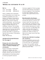
Strömbrytarpanel 12 eller 24 V
ELEKTRISK INSTALLATION
Se fig. sid. 9
SPX FLOW Johnson Pump
länspump/nivåströmbrytare/
strömbrytarpanel
Installera alltid nivåströmbrytare
och panel eller andra strömbrytare
och säkringar mellan batteriets
pluspol (+) och pumpens
plusanslutning (+) (brun kabel).
Pumpens minusanslutning (-)
(svart kabel) ansluts till batteriets
minuspol (-) direkt. Säkringsstorlek
väljs efter pumpens
säkringsspecifikation.
Elanslutningar
Alla elanslutningar måste alltid
sitta över högsta vattennivån.
Kabelskarvarna bör tätas med
ett marint tätningsmedel för att
förhindra oxidation.
Avfallshantering/
materialåtervinning
Vid avfallshantering ska produkten
lämnas för destruktion/återvinning
enligt gällande lagstiftning. Vid
tillämpliga fall demonteras och
sorteras produkten i ingående
materialfraktioner.

4Original instructions
> English
Part. nr. US
12 V – 34-1224 82044
24 V – 34-1225 82044-24
The bilge pump control combined
with an automatic switch is an
excellent installation for your boat.
The panel has a 3-position switch
for Off, manual On, and automatic
operation – the automatic feature
operates in combination with
an automatic switch.
Integrated fuse holder and
operating light. Fuses are not
included. Fuse is selected
according to the recommended
fuse size of the connected pump,
refer to the pump manual.
The switch is in matt black finish.
Size: 73 x 60 mm.
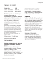
ELECTRICAL INSTALLATION
See fig. page 9
SPX FLOW Johnson Pump
submersible bilge pump/
Automatic Switch/ Bilge pump
control
Always install the switch and bilge
pump control or other switches
or fuses between the positive (+)
terminal of the battery and the
positiv (+) connection of the pump
(brown wire).
The negative (-) connection (black
wire) of the pump to be connected
directly to the negative (-) terminal
of the battery. Fuse size applies to
pump specification.
Electrical connections
All electrical connections must be
placed above the highest water
level. The wire connections should
be sealed with a marine sealant to
prevent wire corrosion. Insulation
or cable sheathings have to be
removed in such a way that they
end well above the highest bilge
water level.
Waste handling/
material recycling
At the products end of life,
please dispose of the product
according to applicable law. Where
applicable, please disassemble
the product and recycle the parts
material.
Bilge pump control 12 or 24 V

5
Übersetzung der Original-Betriebanleitungen
> Deutsch
Art. nr. US
12 V – 34-1224 82044
24 V – 34-1225 82044-24
Die Schalttafel, zusammen mit dem
Niveauschalter ist eine vorzügliche
Kombination für Ihr Boot. Auf der
Tafel sind drei Stellungen - Aus
- Ein - Auto. Der automatische
Betrieb ist möglich, wenn der
Niveauschalter eingebaut ist.
Sicherungschalter und Funktions-
kontrolleuchte sind eingebaut.
Sicherungen sind nicht enthalten.
Die Sicherung wird entsprechend
der empfohlenen Sicherungsgröße
der angeschlossenen
Pumpe ausgewählt, siehe
Pumpenhandbuch. Der Schalter ist
in mattschwarzem Finish.
Größe: 73 x 60 mm.
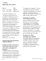
ELEKTRISCHE ANLAGEN
Siehe Fig. Seite 9
SPX FLOW Johnson Pump
Tauchbilgenpumpe/
Niveauschalter / Schalttafel
Den Niveauschalter und die
Schalttafel, oder andere Schalter,
immer zwischen der positiven
(+) Klemme der Batterie und
der positiven (+) Verbindung
an der Pumpe (brauner Leiter)
anschließen.
Der negative (-) Leiter (schwarz)
der Pumpe wird direkt an die
negative (-) Klemme der Batterie
gelegt. Der Nennstrom der
Sicherung bezieht sich auf die
Pumpenspezifikation.
Elektrischer Anschluß
Die elektrischen Verbindungen
müssen auf sicherem Abstand
über dem Hochwasserstand im
Bilgen-
boden angebracht werden. Als
Korrosionsschutz sollen die Leiter
mit einer wasserfesten Dichtung
geschützt werden. Isolierungen
oder Kabelummantelungen müssen
so zurückgeschnitten werden, daß
die Isolierung oder Ummantelung
in einem sicheren Abstand über
dem Hochwasserstand endet.
Entsorgung/Recycling
Nach Lebensdauerende entsorgen
Sie die Pumpe nach den örtlichen
Vorschriften.
Nach Möglichkeit demontieren
Sie Teile der Pumpe um sie dem
Recycling-Process zuzuführen.
Schalttafel 12 oder 24 V

6Traduction du manuel d'instruction d'origine
> Français
Ref. nr. US
12 V – 34-1224 82044
24 V – 34-1225 82044-24
Avec un tableau de commande
pour l’interrupteur vous aurez une
installation parfaite pour votre
bateau. Le tableau comprend un
interrupteur à 3 positions: Arrêt,
Marche mode manuel, Marche
mode automatique - qui fonctionne
en association avec l’interrupteur.
Support fusible intégré et un
indicateur lumineux. Les fusibles
ne sont pas inclus. Le fusible est
sélectionné en fonction de la taille
de fusible recommandée de la
pompe raccordée, se reporter au
manuel de la pompe. L’interrupteur
est noir mat.
Taille: 73 x 60 mm,
INSTALLATION ELECTRIQUE
Voir fig. page 9
Pompe de cale submersible
SPX FLOW Johnson Pump/Inter-
rupteur à flotteur/Tableau de
commande
Toujours brancher l’interrupteur
à flotteur, le tableau de com-
mande, les autres inter-rupteurs ou
fusibles entre la borne positive (+)
de la batterie et la borne positive
(+) de la pompe (fil marron).
La borne négative (-) de la pompe
doit être directement connectée à
la borne négative (-) de la batterie.
Le choix des fusibles se fait en
fonction des spécifications de la
pompe.
Branchements électriques
Tous les branchements électriques
doivent être placés au-dessus du
niveau le plus haut des eaux de
cale. Toutes les connexions et les
bornes doivent être isolées à l’aide
d’un matériau etanche pour éviter
toute corrosion. Le dénudage des
câbles doit être fait de façon à
ce que l’isolant ou le revêtement
extérieur du câble soit bien au-
dessus du niveau le plus haut des
eaux de cale.
Gestion des déchets/recyclage
des matériaux
Lorsque le matériel arrivera en fin
de vie, veuillez le mettre au rebut
en fonction des lois applicables.
Lorsque c'est possible, veuillez
démonter le matériel et recycler les
pièces pouvant l'être
Tableau de commande 12 ou 24

7
Traducción de instrucciones originales
> Español
Pieza. No. US
12 V – 34-1224 82044
24 V – 34-1225 82044-24
El tablero junto con el interuptor
flotante constituyen un
equipamiento muy bueno para una
embarcación. El tablero tiene un
interruptor con tres posiciones:
Off, On manual y operación
automática, que funciona en
combinación con el interruptor
flotante.
Incorpora portafusible y lámpara.
No contiene fusibles. El fusible
se selecciona de acuerdo con el
tamaño de fusible recomendado
de la bomba conectada, consulte
el manual de la bomba.
El interruptor está acabado en
negro mate.
Dimensiones: 73 x 60 mm.
EQUIPO ELÉCTRICO
Ver fig. página 9
Bomba submergible de sentina
Johnson/Interruptor flotante/
Tablero
Instalar siempre el interruptor
flotante de SPX FLOW Johnson
Pump y el tablero y otros
interruptores o fusibles entre el
borne positivo (+) de la batería y el
terminal positivo (+) de la bomba
(conductor marrón).
El terminal negativo (-) de la
bomba debe ser conectado
directamente al borne negativo
(-) de la batería. La capacídad del
fusible depende de la bomba.
Cableado
Todo el cableado debe quedar por
encima del nivel más alto de agua.
Las conexiones deben sellarse con
un compuesto para aplicaciones
marinas a fin de evitar la corrosión
de los alambres. El material
aislante o camisa del cable debe
separarse de tal modo que el
aislante o camisa termine bien por
encima del nivel más alto de agua
de la sentina.
Desguace/Reciclado
Al final de la vida del equipo
disponga de este de acuerdo a
la ley. Donde sea de aplicación
desmonte el equipo y recicle los
diferentes materiales.
Tablero 12 ó 24 V

8Traduzione delle istruzioni originali
> Italiano
Art. nr. US
12 V – 34-1224 82044
24 V – 34-1225 82044-24
Il pannello combinato con
l’interruttore garantisce una
eccellente installazione per la
vostra barca. Il pannello ha un
interruttore a 3 posizioni per
Spento, Acceso, manuale ed
Acceso automatico. In ”Acceso
automatico” il funzionamento
é gestito dall’interruttore.
Portafusibile integrato completo di
luce di spia. Fusibile non incluso.
Il fusibile viene selezionato in
base alla dimensione del fusibile
consigliata della pompa collegata,
fare riferimento al manuale della
pompa. L’interruttore é rifinito in
nero opaco.
Dimensioni: 73 x 60 mm
INSTALLAZIONE ELETTRICA
Vedi fig. pagina 9
Pompa di sentina sommersa
SPX FLOW Johnson Pump/
Interruttore galleggiante /
Pannello
Installare sempre l’interruttore
galleggiante ed il pannello SBP
od altri interruttori o fusibili tra il
terminale positivo (+) della batteria
ed il collegamento positivo (+)
della pompa (cavo marrone).
Il collegamento negativo (-) (cavo
nero) della pompa deve essere
collegato direttamente al terminale
negativo (-) della batteria. La
capacità del fusibile é determinata
dalla specifica della pompa.
Collegamenti elettrici
Tutti i collegamenti elettrici
devono essere posti al di sopra
del livello più alto dell’acqua. I
collegamenti cavo dovrebbero
essere sigillati con un sigillante
marino per prevenire la corrosione.
L’isolamento o la guaina del cavo
devono essere rimossi in modo
tale che l’isolamento o la guaina
terminino ben al di sopra del livello
più alto dell’acqua di sentina.
Gestione dei rifiuti/
riciclaggio dei materiali
Al termine della vita del prodotto
si prega di smaltire il prodotto
secondo le leggi in vigore per
queste operazioni. Quando
possibile, si raccomanda di
smontare il prodotto e riciclare i
materiali dei componenti.
Pannello 12 o 24 V

9
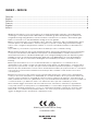
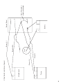
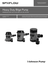
8
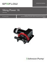
Ultima Switch
Pump
Fuse
Battery
Switch Panel
+
+
+
-
-
-
3
2
1
7
Brown (+)
Black (-)
Note: This cable is
already connected
Brown (+)
Brown/white
Ultima Switch installation with panel

10
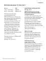
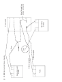
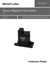
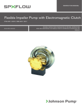
8
1
AS 888
Pump
Fuse
DC supply
Battery
Panel switch
+
+
+
-
+
-
3
2
Automatich switch
7
AS 888 Electrical installation with pandy
Note: This cable is
already connected
+ Brown
(+) Brown pumplead
(-) Black pumplead

11
-
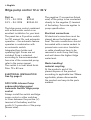
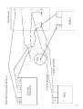
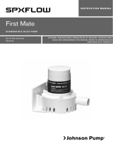
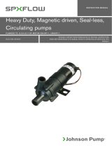
7
Floatswitch
Pump
Fuse
Battery
Switch panel
Electronic
8
Tracer
+
+
-
BRN W.
Black
-
3
2
1
+ +
BRN
+ Brown pumplead
(-) Black pumplead
Electronic Floatswitch with panel


Bilge Pump
Control Panel
IB-101 R05 ISSUED 04/2018 COPYRIGHT © 2018 SPX FLOW INC.
Customer Service & Support - Johnson Pump Marine
SE +46 19 21 83 10
johnson-pump.marine@spxflow.com
US +1 847 671-7867
jp-customerservice@spxflow.com
AUS +61 03 9589 9222
ft.aus.cs@spxflow.com
For more information about our worldwide locations, approvals, certifications,
and local representatives, visit Johnson Pump - Marine at www.spxflow.com
SPX FLOW, Inc. reserves the right to incorporate our latest design and material changes without notice or obligation.
Design features, materials of construction and dimensional data, as described in this bulletin, are provided for your
information only and should not be relied upon unless confirmed in writing. Please contact your local sales representative
for product availability in your region. For more information visit www.spxflow.com.
The green “
>
”
and “
><
” are trademarks of SPX FLOW, Inc.
-
 1
1
-
 2
2
-
 3
3
-
 4
4
-
 5
5
-
 6
6
-
 7
7
-
 8
8
-
 9
9
-
 10
10
-
 11
11
-
 12
12
-
 13
13
-
 14
14


in altre lingue
- français: SPX FLOW Control Panel Manuel utilisateur
- español: SPX FLOW Control Panel Manual de usuario
- Deutsch: SPX FLOW Control Panel Benutzerhandbuch
Documenti correlati
-
 SPX FLOW Bilge Pump Float Switche Guida utente
-
 SPX FLOW Heavy Duty Manuale utente
-
 SPX FLOW Bilge Pump Float Switche Guida utente
-
 SPX FLOW First Mate Manuale utente
-
 SPX FLOW Bilge, Deck Wash and Refueling pump Manuale utente
-
 SPX FLOW Viking Power Waste Water Pump Manuale utente
-
 SPX FLOW Heavy Duty Electro-Magnetic Clutch Pump FB-5001 Series Manuale utente
-
 SPX FLOW CM10/CM30 Manuale utente