Jamara 053371 Manuale utente
- Categoria
- Giocattoli telecomandati
- Tipo
- Manuale utente

No. 053370 EP
No. 053371 EP LiPo
Veloce EP
2,4 GHz
Frequency bands: 2.4GHz Frequency range: 2405,5 MHz - 2475,0 MHz EIRP: 49,09 mW (max. power transmitted) 50/21
IT - Istruzioni di montaggio
GB - Instruction
Informazioni generali
Jamara e. K. non si assume alcuna responsabilità per danni, al prodotto stesso o da esso causati,
che siano riconducibili a un utilizzo non corretto o a manovre errate.Il corretto uso e azionamento
del prodotto è interamente ed esclusivamente a carico del Cliente; ciò include in particolare il mon-
taggio, il caricamento, l‘utilizzo, e nanche la scelta del campo di impiego. Si prega di osservare a
tal ne le istruzioni d‘uso, contenenti informazioni e avvertimenti molto importanti.
General information
Jamara e.K. is not liable for any damage caused to the product itself or through this, provided this
is due to improper operation or handling errors. The Customer alone bears the full responsibility for
the proper use and handling, including without limitation, the assembly, the charging process, the
use and choice of the operation area. Please refer to the operating and user instructions, it contains
important information and warnings.
Questo modello non é un giocattolo!
Attenzione: Tenere lontano assolutamente i bambini inferiori ai 36 mesi.
PERICOLO DI SOFFOCAMENTO! Tenere lontano necessariamente dai bambini.
Contiene pezzi piccoli che possono essere ingeriti.
This model is not a toy!
Warning: Not suitable for children under 36 months. RISK OF SUFFOCATION!
Keep away necessarily from children.
Contains small parts which can be swallowed.
Dichiarazione di conformita’
Jamara e. K. dichiara qui di seguito che il modello „Veloce EP RTR 2,4 GHz,
No. 053370, No. 053371“ è in linea con le norme ed altre rilevanti disposizioni comunitarie
1999/5/EG, 2011/65EU. Piu informazioni:
www.jamara-shop.com/Conformity
Certicate of Conformity
Hereby JAMARA e.K. declares that the products „Veloce EP RTR 2,4 GHz,
No. 053370, No. 053371“ comply with Directives 2014/35/EU, 2014/53/EU and 2011/65/EU.
The full text of the EU Declaration of Conformity is available at the following Internet address:
www.jamara-shop.com/Conformity
Prima di avviare il modello, leggere attentamente tutte le istruzioni per l’uso.
Attenzione! Leggere completamente le avvertenze / istruzioni di sicurezza, questi
sono per la vostra sicurezza può prevenire incidenti / infortuni.
Read the complete instructions and security instructions carefully before using the model.
Caution! Please fully and carefully read warnings/ safety instructions. These are for
our own security and can avoid accidents/injuries.
Questo prodotto è un articolo di modellismo. Ciò signica che il veicolo deve essere sempre sotto-
posto a manutenzione (controllare eventuali danni, controllare i collegamenti a vite, pulire ecc...).
Le parti soggette ad usura come l‘ingranaggio principale, il pignone del motore, bicchierino ecc.
si consumano nel tempo e devono pertanto essere sostituite. Non è sempre possibile evitare gli
incidenti, pertanto è necessario riparare o sostituire anche i danni causati dagli incidenti. Le parti
usurate o difettose a causa di urti o manutenzione insufciente non sono coperte da garanzia, i
costi e le riparazioni sono a carico dell‘acquirente stesso.
This product is a model building article. This means that the vehicle must always be serviced (check
for damage, check screw connections, clean etc...). Wear parts such as the main gear, motor pinion,
bone socket, etc. will wear out over time and must therefore be replaced. Crashes cannot always be
avoided, so crash damage must also be repaired or replaced. Wear parts or defective parts due to
crashes or insufcient maintenance are not covered by warranty, costs and repairs must be covered
by the buyer himself.
Attenzione!
Prima dell‘uso: Accendete prima la trasmittente e poi il modello.
Dopo l‘uso: Spegnere prima il modello e poi la trasmittente.
● Non utilizzare il suo modello fuori della distanzia di vista. Sia la visibilità come la portata
massima del vostro modello dipendono da molti fattori, come il tempo, disturbo di frequenza e il
luogo di utilizzo. Eseguire un test prima di ogni utilizzo del modello con una seconda persona
che tiene ssato il modello. Con questa procedura potete testare come reagisce il modello
durante la perdita del segnale causato per esempio da una batterie scarica oppure la radio
spenta.
Attention!
Before operating: Switch the transmitter on rst then the model.
When nished: First switch off the model then the transmitter.
● Never operate your model beyond sight. Both the maximum visibility as well as the max. range
of your model will depend on many factors such as weather, location and interfering
frequencies. Therefore, before each use perform a range test with a second person securely
holding the model and also check how the model reacts if there is a signal failure e.g. when
empty transmitter batteries are installed.
Attrezzi consigliati + Accessori Recommended Tool + Accessories
No. 190065
Misuratore convergenza
Angle Lange
No. 232060
Power tape silicone rosso
Double sided power tape
No. 232423 medium
Lacca protezione
Locking varnish
No. 281730
Forbici per lexan
Lexan scissors
No. 059273 1:10
Graffette per carrozzeria
Body clips
No. 505401 piccolo/small
Graffette per carrozzeria
Body clips
No. 153059
X-Peak 80 V2
Caricatore
Charger

1
2
5
4
3
2
6
NiMh
Contenuto del kit
1. Modello
2. Telecomando
3. Batteria LiPo (No. 053371)
4. Caricatore LiPo
5. Batteria NiMh (No. 053370)
5. Caricatore USB NiMh
Accessori:
• Telecomando:
4 x AA 1,5V,
Nr. 140267 (4 pezzi)
Dati tecnici:
• Dimensioni:
~ 435 x 320 x 180 mm
• Peso:
~ 2500 g (No. 053370)
~ 2600 g (No. 053371)
• Batteria:
NiMh 7,2 V 2000 mAh
(No. 053370)
LiPo 7,4 V 5000mAh
(No. 053371)
• motore:
Venti 550, 270 W
Le informazioni non sono
garantite. Ci riserviamo il diritto di
apportare modiche tecniche e la
possibile presenza di errori.
Box contents
1. Model
2. Transmitter
3. Battery LiPo (No. 053371)
4. Charger LiPo
5. Battery NiMh (No. 053370)
6. USB-Charger NiMh
Accessories:
• Transmitter:
4 x AA 1,5V,
No. 140267 (4 pieces)
Technical data:
• Dimensions:
~ 435 x 320 x 180 mm
• Weight:
~ 2500 g (No. 053370)
~ 2600 g (No. 053371)
• Battery:
NiMh 7,2 V 2000 mAh
(No. 053370)
LiPo 7,4 V 5000mAh
(No. 053371)
• Motor:
Venti 550, 270 W
No responsibility is taken for the
correctness of this information.n.
Solo per / Only for:
Versione 053371 Solo per / Only for:
Versione 053370
Primi passi - Processo di ricarica
NiMh Processo di ricarica (053370)
Collegare il caricatore USB a una porta USB. Raccomandiamo un adattatore di rete USB (2A)
per la presa di corrente. Le connessioni USB di computer e portatili di solito non possono fornire
corrente sufciente per caricare la batteria. Il LED sul caricatore si illumina di verde. Collegare il
caricatore USB alla batteria NiMh. Il LED rosso del caricatore USB segnala il processo di ricarica.
Se la spina del caricatore e la spina della batteria di trazione non corrispondono, un adattatore di
ricarica è incluso nel vostro modello. Quando la batteria è completamente carica, il LED si illumina
di verde. Assicuratevi assolutamente che il tempo di ricarica non venga superato. Non caricare bat-
terie diverse dalla batteria NiMh in dotazione. Il tempo medio di ricarica per la batteria NiMh vuota
in dotazione è di circa 6 - 8 ore.
Se il LED lampeggia, c‘è un guasto. Si prega di contattare il servizio clienti.
Attenzione:
Caricare solo le batterie adatte con questo caricabatterie. Le batterie adatte sono batterie al nichel-
metallo idruro con max. 6 celle, max. 7,2 V di tensione nominale e massimo 2000 mAh. La batteria
deve avere un connettore Tamiya. Caricare batterie non adatte può danneggiare il caricatore e
la batteria. Pericolo di incendio! Il collegamento di carica del caricabatterie non deve mai essere
saldato o modicato!
Getting Started - Charging process
NiMh Charging process (053370)
Connect the USB charger to a USB port. We recommend a USB adapter (2A) for the grounding
receptable. USB ports of computers and laptops usually cannot provide sufcient current to charge
the battery. The LED on the charger lights up green. Connect the USB charger to the NiMh drive
battery. The red LED of the USB charger signals the charging process. If the plug of the charger and
the plug of the drive battery do not match, a charging adapter is included with your model. When the
battery is fully charged, the LED lights up green. Make absolutely sure that the charging time is not
exceeded. Do not charge any batteries other than the NiMh battery supplied. The average charging
time for the empty NiMh battery supplied is approx. 6 - 8 hours.
If the LED ashes, there is a fault. Please contact the customer service.
Caution:
Only charge suitable battery‘s with this charger. Suitable battery‘s are Nickel metal hydride battery‘s
with max. 6 cells, max. 7,2 V nominal voltage and max. 2000mAh. The battery must have a tamiya
plug. The charging of unsuitable battery‘s can cause damage to the charger and the battery‘s.
Fire Hazard! The charging connection of the charger is not allowed to get altered or soldered to a
different balancer plug type!
Avete acquistato un modello RTR. Ciò signica che il veicolo è in gran parte pronto per l‘uso
immediato. Tuttavia, è essenziale controllare che il modello non presenti possibili danni
meccanici o elettrici o difetti prima e dopo ogni utilizzo. È inoltre necessario vericare la
libertà di movimento di tutti gli elementi mobili e la tenuta dei collegamenti a vite.
You have purchased a RTR model, which means it should be ready for immediate use after
charging all batteries. You need to check the car, electronics and all plastic parts after each
use to make sure no parts are damaged. Also all the moving parts must be checked for their
clearance, bolts and screws that they are tight.
LiPo Processo di ricarica (053371)
Note importanti sull‘idoneità della batteria:
Assicurarsi di utilizzare solo batterie ai Polimeri di Litio con connettore XH balancer. Solo queste
possono essere utilizzate con il caricatore. Altri collegamenti e tipi di batterie non possono essere
utilizzati (si può vericare il rischio di incendio dovuto all‘inversione di polarità o al sovraccarico).
Si prega di contattare il produttore della vostra batteria per sapere se la vostra batteria è adatta. Uti-
lizzare solo batterie LiPo con una capacità di almeno 1600mAh (altrimenti c‘è il rischio di incendio
a causa della corrente di carica eccessiva). Se si utilizzano batterie con una capacità inferiore a
1600mAh, le batterie devono essere approvate per una corrente di carica di 1600mA (carica rapida).
Si prega di chiedere al produttore della vostra batteria se la vostra batteria soddisfa questi requisiti.
È possibile collegare solo una singola batteria alla volta al caricatore. Caricare 2 batterie
allo stesso tempo NON è permesso e causerà danni alla batteria o al caricatore (pericolo di
incendio).
LiPo Charging process (053371)
Important notes on the suitability of the battery:
Make sure to use only lithium polymer batteries with XH balancer connector. Only these may
be used with the charger. Other connections and battery types must not be used (re hazard due to
reverse polarity or overcharging may result).
Please contact the manufacturer of your battery to nd out whether your battery is suitable. Only
LiPo batteries with a capacity of at least 1600mAh must be used (otherwise there is a risk of
re due to excessive charging current). If you use batteries with a capacity below 1600mAh, the
batteries must be approved for a charging current of 1600mA (Speedcharging). Please ask the
manufacturer of your battery if your battery meets these requirements.
You may only connect one single battery to the charger at a time. Charging 2 batteries at
the same time is NOT allowed and will cause damage to the battery or charger (re hazard).

3
1 2 3
4
4x AA
1 2
Inserimento delle batterie nel trasmettitore
Inserire 4 batterie AA nel trasmettitore.
Inserting batteries into the transmitter
Put 4 AA Batteries into the Transmitter
Informazioni relative alle pile:
Le batterie non ricaricabili non devono essere caricate!
Non aprire! Non gettare nel fuoco!
Non usare contemporaneamente pile nuove e pile usate!
Non usare contemporaneamente pile alcaline, standard (zinco-carbone) e ricaricabili!
Le batterie ricaricabili devono essere rimosse dal giocattolo!
Le batterie ricaricabili possono essere ricaricate solo sotto la supervisione di un adulto!
I morsetti di collegamento don devono essere cortocircuitati!
Battery warning:
Non-rechargeable batteries are not to be recharged!
Do not open! Do not dispose of in re!
Do not mix old and new batteries!
Do not mix alkaline batteries, standard (carbon-zinc) or rechargeable batteries!
Rechargeable batteries are to be removed from the toy before being charged!
Rechargeable batteries are only to be charged under adult supervision!
The supply terminals are not to be short-circuited!
IT
1. Ingresso 100 - 240 V
2. Attacchi di bolanciatore 2 cella
3. Attacchi di bolanciatore 3 cella
(Non richiesto per questo modello)
4. LED di stato
GB
1. Power Slot 100 - 240 V
2. 2S Balancer
3. 3S Balancer
(Not required for this model)
4. Status LEDs
LiPo Caricare una batteria
1. Inserire il cavo di alimentazione del caricabatterie in una presa adatta. I LED si illuminano di
verde e indicano che la batteria è pronta per la ricarica
2. Ora collega la batteria vuota al caricatore. Batterie 2S da 7,4V al connettore a 3 poli o 11,1V
batterie 3S al connettore a 4 poli. Non usare la forza e fare attenzione a non invertire la polarità.
I LED diventeranno rossi dopo pochi secondi, indicando che le celle della batteria si stanno
caricando.
Attenzione!
Quando si collega una batteria 2S, solo i primi 2 LED (Cell1-2) diventano rossi, il LED 3
(Cell 3) rimane verde. Quando si collega una batteria 3S, tutti i LED (Cell1-3) diventano
rossi.
Non appena una cella della batteria è completamente carica, il LED corrispondente diventa
verde. Poiché le celle sono caricate individualmente, è possibile che una cella sia
completamente carica prima delle altre, a seconda dello stato della batteria. Lasciare sempre la
batteria sul caricatore no a quando tutte le celle collegate sono completamente cariche (verde)
per permettere al caricatore di bilanciare la batteria.
Charging a battery
1. Plug the power cord of the charger into a suitable socket. The LEDS light up green and indicate
that the charger is ready for charging.
2. Now connect the empty battery to the charger. 7.4V 2S batteries to the 3 pin connector or 11.1V
3S batteries to the 4 pin connector. Do not use force and pay attention to reverse polarity. The
LEDs change to red after a few seconds and indicate that the battery cells are charging.
Attention:
When connecting a 2S battery, only the rst 2 LEDs (Cell1-2) change to red, LED 3 (Cell 3)
will remain green. When 3S batteries are connected, all LEDs are red (Cell1-3).
As soon as a the battery cell is full, the corresponding LED changes to green. Because the cells
are charged individually in a balanced way, it is possible that one cell is fully charged earlier than
the others. Always leave the battery on the charger until all connected cells are fully charged
(green) to allow the charger to balance your battery
Riconoscimento di una batteria carica.
Quando si collega una batteria carica al caricatore, i LED diventeranno rossi per alcuni secondi e poi
torneranno verdi. Questo signica che la batteria è già completamente carica.
Riconoscimento di una batteria difettosa.
Se i LED rimangono verdi quando si collega una batteria vuota, c‘è un difetto nella batteria (difetto
della cella o scarica profonda). In questo caso, scollegare immediatamente la batteria dal caricatore
e utilizzare un‘altra batteria.
Detecting a full battery.
When you connect a full battery to the charger, the LEDs will turn red for a few seconds and then
turn green again. This means that the battery is already fully charged.
Detecting a defective battery.
If the LEDs remain green when an empty battery is connected, there is a defect in the battery (cell
defect or deep discharge). In this case, immediately disconnect the battery from the charger and
use another battery.
Attenzione!
Dopo ogni carica e importante di: Scollegare sempre subito la batteria dal caricatore
ed il caricatore dalla rete elettrica. Se dopo la carica si lascia collegato l’uno o l’altro
può causare danni alla batteria, al caricatore o addirittura alla rete elettrica (pericolo
di incendio).
Danger!
Always disconnect the battery from the charger immediately after charging. Always
disconnect the charger from the power supply immediately after disconnecting the
battery. Inserting the rechargeable battery or charger after charging will result in da-
mage to the battery, charger or the power supply (re hazard).

1
4
50 5080
50 5081
07 9996
50 5079
505080
505081
079996
505079
Attenzione!
Il veicolo è dotato di una Pivot sospensione anteriore. Questa ha
una serie di vantaggi. E ‚molto robusta e la manutenzione e´molto
facile. Questo è impostato in fabbrica in modo che la carreggiata
non permette agli cardani di saltare fuori. Come con qualsiasi mo-
dello, dopo l´inizio dell’uso si rallentano di qualche millimetro sia
la sospensione sia i bulloni. Questo gioco minimo, po’ abbastare
sotto massimo sforzo per fare saltare fuori i cardani. Pertanto è
necessario per assicurarsi prima di ogni uso che tutte le viti, dadi,
giochi ecc., sono ssate correttamente. La vita esterna in plastica
505080 serva per ssare il fuso a snodo sulla vite a sfera. Questo
non deve essere serrata troppo forte. In caso contrario, lo sterzo
non si muove liberamente e la guida può essere inuenzata ne-
gativamente.
Attention!
Your vehicle has a pivot front suspension. This has a number of
advantages. It is very robust and easy to maintain. The set-up of
the car has been done so the drive shaft will not pop out. As with
any model, screws and bolts can losen during break-in of the car.
This can result in tolerance of the drive shaft. The drive shaft can
then pop out if high pressure is applied. The inner ball screw will
enable you to adjust the tolerance resulting in ne adjustments of
the track width. For best results when setting up the pivot ball for
the rst time, please always adjust the upper and lower pivot in
the same way. Fasten as far as the pivot can still be pulled up and
down easyly but not as far that it will pop out if you give full stee-
ring angle. The outer plastic socket screw is only used for securing
of the steering knuckle. This should not be too tight, otherwise the
steering is not smooth and the handling can be adversely affected.
Attenzione!
Il giunto omocinetico anteriore e posteriore assorbe la maggior
parte dell’energia del motore e lo passa all’asse anteriore e pos-
teriore. Per questo, le vite a brugola che tengono il giunto omoci-
netico sul asse di uscita prima del primo utilizzo e in intervalli
regolari (5-7 inserti) devono essere controllati e se necessario av-
vitare. Nel giunto omocinetico anteriore e posteriore deve essere
inserito un anello di gomma. Controllare il gioco del albero motore.
Il margine del gioco dovrebbe essere di ca. 1-2 mm. Potrebbe
essere necessario spostare il giunto omocinetico per adattare il
gioco. Qui deve svitare le vite senza testa con un cacciavite e
regolare il giunto omocinetico. Dopo di che avvitare le vite senza
testa. In caso contrario l’omocinetico si sposta sul albero di uscita
e l’omocinetico e l’albero centrale possono essere danneggiati
Attention!
The front and rear bone pan absorbs most of the motor‘s energy
and directs it to the front and rear axles. Therefore, the hexagon
socket screws which hold the bone pans on the transmission out-
put shafts must be checked and, if necessary, tightened before
the rst use and in regular intervals e.g 5-7 uses. Insert a rub-
ber ring to the front and the back connection cup. Please check
the tolerance of the drive shaft. The tolerance should be approx.
1 – 2mm. You may have to move the connection cups to adapt
the tolerance. Therefore you need to loosen the grub screws to
adapt the connection cup. Afterwards tighten the grub screws. If
not, the connection cups will move on the gear output shaft. That
might cause the connection cup and the middle drive shaft to get
damaged.
● Mettete la batteria nel vano della batteria, a bordo del veicolo. Fare attenzione che la batteria
sia correttamente fissata con i 2 clip in dotazione e che la batteria non abbia un gioco
eccessivo nel vano appropriato.
● Ora collegare la batteria con il regolatore del modello. Se la spina del regolatore e la spina
della batteria non corrispondono, un cavo adattatore è incluso con il modello.
● Leggere il capitolo sulla trasmittente. Accendere la trasmittente e assicurarsi che i trim siano
in posizione neutrale
● Tenere il modello in aria per il caso che il motore si metta a girare a tutto gas.
● Ora accendere il regolatore di velocità tramite l`interruttore ON / OFF.
● Vi incoraggio ad attivare il ricevitore integrato in unità fail-safe. Al momento della consegna
è spento.
● Se questa è la tua prima auto rc, si consiglia di guidare s
● Put the battery into the battery holder in the vehicle and secure it with the velcro straps.
Make sure that the battery is safely locked in the battery holder without any great play.
● Now connect the battery to the speed control in the model. If the plug of the speed control and
battery do not match, then you will nd a connection lead in your box
● Turn the radio on and make sure all the trim buttons on the transmitter are in neutral position.
Read the chapter for usage of the transmitter.
● Keep the car in the air in case that the motor turns at full power.
● Switch the speed control on the On / Off switch.
● We encourage you now to activate your receiver‘s built-in Failsafe unit.
On delivery it is turned off. (see chapter Fail Safe).
● If this is your rst rc car, we recommend to drive it on a small test track to familiarise yourself
with the control of the vehicle and the controls of the transmitter.
Attenzione.
Spegnere sempre il modello subito dopo ogni utilizzo. Subito dopo ogni utilizzo, la
batteria deve essere scollegata dal modello. La batteria può essere scaricata com-
pletamente se viene lasciata accesa accidentalmente o se viene lasciata inserita. La
scarica profonda causa la perdita di energia della batteria o può essere danneggiata
a tal punto che la carica o la scarica non è più possibile o la batteria può autoaccen-
dersi durante la carica o la scarica (pericolo di incendio). Non tentare mai di caricare
o scaricare batterie completamente scariche. La tensione della batteria LiPo non
deve mai scendere sotto i 6 volt e quella della batteria NiMh non deve mai scendere
sotto i 4 volt per evitare una scarica profonda. La batteria LiPo completamente carica
ha una tensione di circa 8,4 volt e la batteria NiMh di 8,5 volt. Dopo l‘uso, le batterie
intatte devono essere ricaricate completamente subito dopo una fase di raffredda-
mento di minimo 10 minuti e al più tardi dopo 12 ore per evitare una successiva
scarica profonda per autoscarica. Se le batterie non vengono utilizzate o conservate
per un lungo periodo di tempo, è necessario controllarne la tensione ossia il dann-
eggiamento almeno ogni 3 mesi (con LiPo minimo 8 Volt, con NiMh minimo 7,4 Volt)
se necessario, ricaricarle o smaltirle.
Danger.
Always switch off the model immediately after each use. Immediately after each use
the battery should be disconnected from the model. The battery can be deeply di-
scharged by leaving it switched on accidentally or leaving it plugged in. Deep di-
scharge causes the battery to lose power or can be damaged to such an extent that
charging or discharging is no longer possible or the battery can self-ignite during
charging or discharging (re hazard). Never attempt to charge or discharge deep-
discharge batteries. The voltage of the LiPo batteries should never be under 6 volt
and the NiMh battery never under 4 Volt to avoid a depth discharge. The fully charged
LiPo battery has a voltage of approx. 8,4 Volt and the NiMH battery 8,5 Volt. After
usage, the intact battery has to be fully charged after a cooling phase of at least 10
min but not longer than 12 hrs. This is to avoid a deep discharge caused by a self-
discharge. When not using or storing the battery´s it has to be checked at least every
three months for voltage (For LiPo min. 8 Volt, for NiMh min. 7,4 Volt.) or damage and
if necessary charged or disposed.
Batteria/Battery
Regolatore
ESC
ON/OFF
Batteria/Battery
Regolatore
ESC
ON/OFF

5
C
A
B
D
E
G
H
F
I
6
12
3
5
4
Programmazione del gruppo integrato di FailSafe
1. Descrizione della Funzione
L’unità FailSafe è concepita principalmente per l‘utilizzo sulle imbarcazioni e sui veicoli. Serve
per evitare la perdita del modello, determinando la chiusura del gas, nell’eventuale assenza
di segnale. Se la ricevente perde il segnale della trasmittente, il servo del gas o regolatore di
velocità ritorna automaticamente sulla posizione programmata inizialmente.
2. Impostazione
a. Accendere la trasmittente
b. Accendere la ricevente. Il segnale LED lampeggia continuamente e indica che la ricevente
è pronta.
c. Spostare sul trasmettitore la leva dell‘acceleratore nella posizione di freno, o zona spento
nel regolatore di velocità. Tenere la leva del gas su questa zona.
d. Premere il pulsante Imposta sul ricevitore. Il segnale LED lampeggia per 3 secondi (vedi
illustrazione a sinistra).
e. L‘impostazione è salvata e si può portare la leva dell’acceleratore in posizione neutra.
3. Prova delle impostazioni
a. Accendere la trasmittente.
b. Accendere la ricevente.
c. Spegnere la trasmittente.
d. Ora la ricevente perde il segnale e conduce il servo del canale gas o il regolatore di veloc
ità sulla posizione in precedenza programmata.
e. Seguire la procedura descritta sopra, il processo FailSafe funziona correttamente.
How to setup the fail safe function
1. The instruction of function
The function of protection of losing control is mainly for r/c boats and cars and keeps them
away from damage through throttle channel. When the receiver is out of control signal, the
receiver of throttle will automatically return to the initial position which set up before starting to
avoid the error action :
2. How to set the function
a. Switch on the transmitter power and enter into the working condition
b. Connect the receiver with power and enter into the working condition, the signal light
on receivewill blink all the time.
c. Control the throttle of transmitter and keeps the servo or ESC in the neutral position.
d. Press the setting button, the LED will be ash for 3 seconds (see on pict. left).
e. Release the setting button. The setting is nished.
3. Testing
a. Switch on the transmitter and enter the working condition.
b. Contact the receiver with power and enter the working condition.
c. Turn off the power of transmitter.
d. The throttle of servo will be set automatically.
e. Finish these steps above means the setting is ok.
2,4 GHz
Antenna
Antenna
Ricevente/Receiver
Allacciare la trasmittente alla ricevente
In un moderno sistema di 2,4 GHz, è indispensabile che la
trasmittente e la ricevente vengano connesse insieme a bordo del
modello. La ricevente accetta quindi solo i segnali della
trasmittente. Se per qualsiasi motivo si dovesse effettuare un
nuovo allacciamento“connessione”, eseguire le seguenti
operazioni:
1. Sostituire nella trasmettente le batterie scariche con altre
cariche o nuove. Lasciare spenta la trasmettente.
2. Inserire la spina di accoppiamento in dotazione nell’uscita del
canale 3.
3. Collegando la batteria con la ricevente, si accende il sistema
ricevente. Secondo la versione di software usata, la
ricevente segnala in modo differente la modalità di
binding. (esempio: il Led può lampeggiare, restare
accesa o completamente spenta). Il processo di binding in
se è uguale per tutte le versioni. Il Led sulla ricevente inizia
lampeggiare e cosisegnala che la ricevente si trova in
modalità di binding.
4. Tenere premuto il pulsante di connessione sulla trasmittente,
mentre si accende la stessa. E. Il trasmittente inizia a
lampeggiare e cosi segnala che si trova in modalità di binding.
5. Rilasciare il pulsante di connessione della trasmettente e
rimuovere la spina di connessione nella ricevente. Spegnere
laricevente e la trasmittente.
6. Adesso spegnete la trasmittente. Il sistema memorizza il
collegamento.
7. Installare correttamente tutti gli accessori e controllare con
molta attenzione.
8. Se la funzione non avesse successo, ripetere la procedura di
connessione.
Vi invitiamo ad attivare ora l’unità Failsafe integrata nel ricevitore.
Alla consegna è spento.
Montare l‘antenna a 2,4 GHz in verticale come mostrato in gura.
Non permettere a nessun oggetto metallico di entrare in contatto
con l‘antenna o di schermarla, poiché ciò ridurrebbe il raggio
d‘azione.
Binding the receiver to the transmitter
In the delivery state, the transmitter is already bound to the re-
ceiver. If the model does not respond to the transmitter, try binding
it again.
For this purpose, proceed as follows:
1. Put the battery into the model.
Now connect the battery to the speed control in the model.
2. Plug the binding plug (included) into the channel 3 socket on
the receiver.
3. Switch the receiver system on. Depending on your soft-
ware version of your receiver indicates the different bin-
ding mode (instead of ashing lights for example LED or
remains out completely). The binding process as such is in
all versions. The receiver LED will begin to ash indicating
that the receiver is in bonding mode.
4. Press and hold down the binding button on the transmitter
whilst switching it on.
5. The transmitter will begin to ash indicating that the receiver
is in bonding mode.
5. Release the binding button on the transmitter and turn off the
controller. Release the binding plug from the receiver.
7. Switch of the transmitter. And remove the binding wire. The
system be bound at the next start .
8. If the receiver fails to bond or does not function after bond-
ing repeat the above procedure until a successful bonding is
achieved.
We encourage you now to activate your receiver‘s built-in Failsafe
unit. On delivery it is turned off.
Mount the 2.4 GHz antenna vertically as shown in the diagram. Do
not allow any metal object to come into contact with the antenna or
to shield it as this will reduce the range.
Fail Safe
Setup LED Connettore di
collegamento
Binding Plug
Vista laterale destra
1. Scatola di programmazione
2. Volante
3. Leva del gas
4. Vano Batterie
5. Presa di carica
6. Collegamentoper cavo Simulatore
Se si carica attraverso una presa, si prega di
aprire il coperchio della batteria. Viene usato
per il raffreddamento
Settore di programmzione
A. Direzione Reverse
B. Power LED
C. Direzione -Trim
D. Interruttore on /off
E. Gas Reverse
F. Power Check
G. Pulsante collegamen to Binde
H. Dual-Rate
I. Gas Trim
Trimmung
Se le ruote non puntano dritti in avanti, anche
se il volante della trasmettente è in posizione
neutrale, è possibile ottenere aiuto con il trim
della trasmittente nella posizione corretta.
Trim L/R = Sterzo
Se le ruote girano in avanti o indietro, anche se
nessun comando è stato dato attraverso il tras-
mettitore, poi anche l‘acceleratore deve essere
tagliato sul trasmettitore.
Trim V/R = Avanti / Indietro
Inserimento delle batterie
• Togliere il coperchio del scomparto batterie.
• Inserire 4 x AA batterie nella giusta
posizione, facendo attenzione ai poli.
• Rimettere il coperchio del scomparto
batterie.
Controls
1. Programming Box
2. Steering Wheel
3. Throttle Lever
4. Battery Hatch
5. Charge Socket
6. Simulator Cable Socket
If charging the batteries via the charging socket,
the battery hatch cover should be removed to
ensure sufcient cooling.
Programming Panel
A. Steering Reverse (changed)
B. Power LED
C. Steering Trim
D. ON/OFF Switch
E. Throttle Reverse (changed)
F. Power Check
G. Binding Button
H. Dual-Rate (maximum steering deection)
I. Throttle Trim
Trim
If the wheels do not point straight forward even
though the steering wheel on the transmitter is
in neutral, you can adjust it with the trim button
on the transmitter.
Trim L/R = steering
Should the wheels rotate forward or backward,
even though no command was given through
the transmitter, then also the throttle needs to
be trimmed on the transmitter.
Trim V/R = forward/backward
Insert the batteries
• Remove the battery compartment cover.
• Fit the 4 x AA batteries, observe the correct
polarity.
• Replace the battery hatch
Trasmittente 2,4 GHz 2CH Transmitter 2,4 GHz 2CH

6
Regolatore
Dati technici:
Voltaggio 7,2 - 7,4 V
Batterie 2 Lipo | 6 NiCd/NiMh Celle
Resistenza interna Fwd: 0.002 Ohm, Bwd: 0.004 Ohm
BEC Tensione BEC 2A/5V (Linear mode BEC)
Uso RC-Car 1:10
Protezione Sottotensione
Carico continuo 40 A
Dimensioni ~ 45 x 32 x 26 mm
Controller
Technical Data:
Operating Voltage 7,2 - 7,4 V
Battery Pack 2 Lipo | 6 NiCd/NiMh Cells
Internal Resistance Fwd: 0.002 Ohm, Bwd: 0.004 Ohm
BEC Voltage BEC 2A/5V (Linear mode BEC)
Intended use RC-Car 1:10
Protection Circuit Under voltage cut off
Continuous load 40 A
Size ~ 45 x 32 x 26 mm
Attacco per la batteria
Battery connector
Cavo di allacciamento
del regolatore
Signal wire
Pulsante ON/OFF
On/Off switch
Attacco per la motore
Motor connector
Attacco per la motore
Motor connector
IT
Se si vuole disabilitare la funzione indietro, basta impostare il
jumper su disabilitazione. Se il jumper è impostato per abilitare la
funzione indietro è abilitato.
GB
If you want to disable the backward function just set the jumper
to disable. If the jumper is set to enable the backward function
is enabled.
Se si utilizza una batteria Lipo, é necessario attivare il Lipomodo attraverso il Jumper (con-
nessione ponticello). Prima di raggiungere la sua tensione minima, il suo regolatore si speg-
nera. Solo cosi la batteria Lipo viene protetta del sottocarico o eventuali danni! Sulla soglia
di 6 V tensione totale, il regolatore si spegne per evitare che la batteria si sottocarica. Se si
utilizza una batteria NiMh deve mettere il jumper in posizione NiMh. Il regolatore
non si spegne a 6 V di tensione totale ma permette una scarica di ca. 4 V tensione totale.
This regulator has two battery modes which will be set with jumpers. If you are using a Lipo
battery this jumper has to be set to Lipo. This function protects the lipo battery against deep
discharge and possible damage due to deep discharge! At a threshold voltage of 6 V total
the esc switches autom. off to safe the battery from under voltage. If you are using a NiMH
battery this jumper has to be set to NiMh. The controller allows a voltage less than 6 V down
to 4 V.
ATTENZIONE
Il tuo modello è protetto d’antispruzzo. Non impermeabile!
Non guidare in pozzanghere dove l‘acqua è più alta della box ricevente. Non immergere il regola-
tore sott‘acqua. Se la ricevente oppure il regolatore all’interno si bagna, separare immediatamente
la rete elettrica e lasciarlo asciugare a sufcienza. Danni causati da uso improprio o mancanza di
manutenzione del modello non sono coperti dalla garanzia.
WARNING
Your controller is Splash-proof. Not waterproof.
Avoid puddles that are higher than the controller is installed in the vehicle. Do not get the model
under water. After each ride in the wet, the complete controller must be thoroughly dried and lubri-
cate the mechanical components. Damage caused by improper use overload or lack of maintenance
is not covered under warranty.
Attivazione del regolatore
Nell’attivazione procedete come segue:
• Accendere la trasmittente e assicurarsi che la regolazione della corsa del canale gas è
impostata esattamente su + / - 100%.
• Collegare la batteria, controllare che la batteria è collegata con la polarità corretta e che il
regolatore non sia ancora acceso.
• Accendere la ricevente.
• Quando la batteria è collegata, il regolatore è pronto. Siate molto cauti, ci sono rischi
signicativi di lesioni, tramite la partenza di motori ad improvviso.
• Collegare la batteria immediatamente prima dell´inizio d´uso con il regolatore e rimuovere
subito dopo l´uso. Prima dell’utilizzo del modello, fare un test del raggio d´azione.
• Cosi controllate tutti i campi d´uso (tutto gas, a mezzo gas e minimo), se non vi è alcuna
interferenza. Prestare in oltre attenzione ai servi. Un vibrazione dei servi o deviazioni non
controllate, segnala in oltre dei guasti.
• Se si desidera attivare il freno, mentre il veicolo è in movimento in avanti e lo stick del gas è in
posizione avanzata, è necessario spostare lo stick velocemente e invertire la posizione.
• Per mettere la retro-marcia, spostare lo stick in posizione neutra, attendere qualche istante e
poi portare lo stick di là di questo punto, nella posizione inversa desiderata.
Using your controller
To operate the ESC, proceed as follows:
• Switch on your transmitter and ensure that the throw for the throttle channel is in the middle.
• Ensure that the receiver switch is in the OFF position and connect a battery pack ensuring the
correct polarity (+ and -).
• Switch the receiver system ON.
• Once a battery is connected the system is ‘live‘ and extreme caution must be exercised to
prevent injury due to the motor suddenly starting to turn.
• Do not connect the battery pack until directly before operating the model and disconnect the
pack immediate after use.
• Conduct a range test before running the model for the rst time. This test should be carried out
at full, half and low throttle and if the servos jitter or make uncontrolled movements do not
operate the model until the reason for the interference has been established and corrected.
• When the vehicle is being driven forwards, pulling the throttle back past the neutral position will
cause the vehicle to brake. To make the vehicle then reverse, the throttle stick must rst be
moved back to the neutral position for a short period and then the model will reverse.
• If you want to disable the backward function just set the jumper to disable. If the jumper is set to
enable the backward function is enabled.
Congurazione del vostro controllore
Il regolatore di velocità si calibra automaticamente sul segnale del trasmettitore. A tal ne, il pulsante
di trim del canale del gas sul trasmettitore deve essere impostato su neutro. Accendere il trasmet-
titore e poi il regolatore di velocità. Il regolatore di velocità segnala la calibrazione con una breve
melodia ed è pronto per l‘uso. Nel caso in cui il regolatore di velocità non abbia un segnale chiaro o
il controllo del trim non sia impostato su neutro, il regolatore di velocità non si inizializza.
Conguring your controller
The speed controller automatically calibrates itself to the transmitter signal. For this, the trim button
of the gas channel at the transmitter must be set to neutral. Turn on the transmitter and then the
speed controller. The speed controller signals the calibration with a short melody and is ready for
use. In case the speed controller has no clear signal or the trim control is not set to neutral, the speed
controller will not initialize.
Per la messa in funzione del sistema, mettere in atto anche le seguenti precauzioni:
• Mettere solo batterie entro i limiti tecnici consigliati.
• Lasciare raffreddare bene il regolatore prima di rimetterlo in funzione.
• Rimuovere la batteria dal modello dopo ogni utilizzo.
• Attivare necessariamente sempre prima la trasmettente e poi la ricevente, allo spegnimento del
sistema, procedere in senso inverso.
• Utilizzare solo cavi e connettori di alta qualità.
• Creare un buon condotto di raffreddamento per il regolatore, non avvolgerlo per alcun motivo
con gommapiuma o simili.
When using the controller please observe the following safety notes:
• Use only batteries which not exceed the max. operating voltage (2 Lipo cells | 6 NiCd/NiMh
cells).
• Allow the ESC to cool down completely before operating it again.
• Remove the battery from the model when not in use.
• Always switch off the receiver rst and then the transmitter. On switching on, switch on the
transmitter rst and then the receiver.
• Only use top quality cables and connectors.
• Make sure that the ESC is adequately cooled and never wrap the unit in anything that insulates.

505078
505075
505073
505071
505074
505072
505085
505076
079989
505078
505075
505074
505073
505024
EP - 505022
505023
505024
505076
505071
505085
079989
505081
079996
505079
079989
505099
505100
505080
7
Montaggio di trasmissione
anteriore
Front gear assembly diagram
No. 505155
Diff.ant./post.completo
Differencial complete
Montaggio differenziale posteriore
Rear gear assembly diagram
No. 505155
Diff.ant./post.completo.
Differencial complete
Montaggio Pivot anteriore
Steering assembly diagram
Prima dell’uso del prodotto si prega di vericare tutti i
bulloni ed i collegamenti della parte elettronica. Il veicolo
disponedi una sospensione anteriore Pivot Ball. Questo ha
numerosi vantaggi. E‚ molto robusto e di facile manutenzi-
one. L’impostazione di fabbrica non permette che gli alberi
di trasmissione saltano fuori durante la guida. Per qualsiasi
modello in azione, delle parti meccanica si possono allen-
tare tramite i vibrazioni. Un minimo gioco può essere sufci-
ente che durante la guida si perdono gli alberini. Pertanto,
è anche necessario assicurarsi che tutti i bulloni, dadi e vite
siano controllati prima di ogni utilizzo. Con la vita a sfera
(cod. 505081 vedi lista di ricambio) si regola il giusto s-
saggio di questa parte meccanica. Consigliamo di avvitare
la vita superiore e inferiore nel stesso modo, in modo di non
causare un bloccasterzo (tramite gli alberi di trasmissioni)
durante la manovra di sterzo. Ma di fare anche bene atten-
zione di non lasciare un gioco troppo grande, altrimenti si
rischia di perdere gli alberi di trasmissione. La calotta es-
terna in plastica a (505080) serve solo per ssare il fuso a
snodo sulla vite a sfera. Consigliamo di non avvitare questo
coperchio in modo troppo serrato.
Before each use make sure to check all bolt connections
and cable connections. Your vehicle has a pivot front sus-
pension. This has a number of advantages. It is very ro-
bust and easy to maintain. The set-up of the car has been
done so the drive shaft will not pop out. As with any model,
screws and bolts can losen during break-in of the car. This
can result in tolerance of the drive shaft. The drive shaft
can then pop out if high pressure is applied. The inner ball
screw (item No.: 505081) will enable you to adjust the to-
lerance resulting in ne adjustments of the track width. For
best results when setting up the pivot ball for the rst time,
please always adjust the upper and lower pivot in the same
way. Fasten as far as the pivot can still be pulled up and
down easyly but not as far that it will pop out if you give full
steering angle. The outer plastic socket screw (item No.:
505080) is only used for securing of the steering knuckle.
This should not be too tight, otherwise the steering is not
smooth and the handling can be adversely affected.

8
505097
505054
505082
079996
505054
505087 079989
505064
505029
505029
Montaggio assetto posteriore
Rear shaft mount assembly
Montaggio ammortizzatori
Shock assembly
Montaggio Servo Saver
Buffer assembly

505167
506119
505027
505093
505025
9
Montaggio piastra radio
Upper plate assembly
Montaggio motore
Motor assembly

LED-Stecker
LED-connector
Empfänger Kanal3
Receiver-CH3
A
B
B
A
A
A
BB
10
Spring travel
Turnbuckle
turn shorter = Toe-out
turn more = Toe-in Rear camber
IT - In stato di consegna, i LED non sono attivi.
GB - The LED´s are not connected on delivery under certain
circumstances.
IT - Il connettore per il LED si trova nella scatola della radio
GB - The LED connector is stored in the receiver box.
IT - Aprire la scatola ed estrarre la spina dei LED ed il
ricevitore.
GB - Open the receiver box and take out the LED connector
and the receiver.
IT - Inserire la spina del LED nel ricevitore sul canale 3 (CH3).
Inserire il cavo nero (meno) sulla destra esteriore
GB - Put the LED connector into the receiver to channel 3 (CH3).
The black line (minus) belongs to the right side.
IT - Installare il ricevitore e cavi attentamente nella scatola.
Assicurarsi che i cavi corrono attraverso la guida esterna.
Non fratturare i cavi.
GB - Put the receiver and the wiring back to the receiver box and
take care to install the wiring proberly. Dont squeeze the
wiring.
IT - Chiudere la scatola del ricevitore.
GB - Close again the receiver box with the two pins.
IT - Appena acceso il veicolo, si attivano anche i LED.
GB - If you activate the model now, the LED´s are activ.
Tenditore
girare più breve = Toe-out
girare più = Convergenz
Corsa della
molla
Inclinazione
posteriore
IT - Impostazione dell’assetto / sospensione
I seguenti impostazioni sono possibile:
Convergenza anteriore
A Convergenza negativa:
Sterzo e meno diretto e la
macchina tende a sovrasterzare.
Guida diritta più precisa.
B Convergenza positiva:
Sterzo e più diretto e la macchina tende
a sottosterzare. Guida diritta meno
precisa.
GB - Suspension Settings
The following settings are possible:
toe-in / toe-out
A Toe-in: The responsiveness of the steering is
less direct and the vehicle tends to
oversteer, but it has better directional
stability.
B Toe-out: More direct steering response and
understeer, but has a worse directional
stability.
teso
rm teso
rm
morbido
soft
Angolo sospensione
Shock angle
Suspensione molla
Spring tension
morbido
soft
Inclinazione Positivo/Negativo
anteriore e posteriore
A Negativo:
Migliore aderenza nel terreno.
Poiché i bordi delle ruote si
sollevano nel sottosuolo
mentre la macchina entra in
curva. Questo permette una
velocità più elevata nelle cur
ve. Consigliamo ca. 1,5 gradi
negativo anteriore e 0 grado
posteriore. Inclinazione
eccessiva causa un
peggioramento della qualità
guida.
B Positivo:
Inclinazione positivo è da
evitare, dato che questo
causa un guida non precisa.
Negative camber / positive
camber front and rear
A Negative camber:
Better grip on terrain, as the
edge of the wheels stem into
the ground allowing higher
cornering speed. We
recommend approx. imately
1.5 degrees negative front and
an ave rage of 0 degree to the
rear. An excessive negative
camber angle can deteriorate
the ride quality.
B Positive camber:
A Positive camber should be
avoided in your vehicle due to
poorer ride quality.

11
Clip
front mounted =
higher caster
rear mounted =
lower caster
Spring tension
(less or more clip)
Shock angle
Track front
Caster
Spring tension
(less or more clip)
Shock angle
rear / top Rear camber
Angolo di inclinazione
Caster angle
Clip
montato anteriore =
Inclinazone alto
montato posteriore =
Inclinazione basso
IT - Inclinazione alto/basso anteriore
Basso: Inclinazione bassa ha una guida dritta
peggiore, ma un sterzo più preciso e una
migliore entrata in curva.
Alto: Una rotella più alta permette una migliore
traiettoria in linea retta, ma può portare a un
comportamento di sterzata più scadente.
GB - Front caster high / low
Less caster: Less caster has a worse directional
stability, but provides a better steering on
corner entries.
High caster: A higher caster has a better directional
stability, but can result in worse corner
turn-in.
teso
rm
morbido
soft
Angolo sospensione
Shock angle
Suspensione molla
Spring tension
Suspensione molla duro/morbido
anteriore e posteriore
Duro: Risposta più diretta della
sospensione,ma con a
derenza ridotta.
Morbido: Risposta meno diretta della
sospensione, ma con
aderenza più alta.
Angolo sospensione morbido/teso
anteriore e posteriore
Morbido: Sterzo diretto
Teso: Sterzo meno diretto
Corsa molla alto/basso
anteriore e posteriore
Basso: Minore altezza da terra e
centro di gravità più basso
Alto: Maggiore altezza da terra e
centro di gravità più alto
Spring tension hard / soft front and rear
Harder: More direct response of
the suspension but
reduced grip.
Softer: Less direct response of
the chassis but more grip.
Damper angle soft / rm
front and rear
Soft: More direct steering
Firming: Less direct steering
Spring defelxion
more / less front and rear
Less: Less ground clearance
and lower center of
gravity.
More: More ground clearance
and higher center of
gravity.
Punti impostazione Setting points
Suspensione molla
(basso o meno clip)
Suspensione molla
(basso o meno clip)
Angolo sospensione
posteriore / sopra Angolo
sospensione
Inclinazione posteriore Inclinazione anteriore
Inclinazione

12
Punti impostazione Setting points
Suspensione molla
Spring tension
Angolo sospensione
Shock angle
Angolo sospensione
Shock angle
Angolo sospensione
Shock angle
Inclinazione Shock angle
(Solo vite interna)
Camber
(only inner screw)
Suspensione molla
Spring tension
Angolo sospensione
Shock angle
Angolo sospensione
Shock angle
Angolo sospensione
Shock angle
Angolo sospensione
Shock angle

13
Soluzione dei problemi
Dopo l‘accensione il motore non parte e non rilascia alcun segnale acustico.
1. La batteria o il collegamento alla batteria non sono in ordine.
- Controllare i cavi, connettori e batteria.
Dopo l‘accensione, il motore non si avvia, viene emesso un segnale in un ciclo di 1 sec.
1. La tensione di ingresso non è corretta, è troppo alta o troppo bassa.
- Controllare il livello di tensione della batteria.
Dopo l‘accensione, il motore non si avvia, viene emesso un segnale in un ciclo di 2 sec.
1. Il segnale di ingresso viene riconosciuto come non corretto.
- Controllare la trasmittente e il ricevitore, nonché il cavo di collegamento del ricevitore del
regolatore.
Il motore gira in una direzione errata.
1. I collegamenti del motore in senso inverso.
- Sostituire due cavi di collegamento tra il motore e il regolatore.
DImprovvisamente il motore non gira più
1. Il segnale d´ingresso non è corretto.
- Controllare trasmettitore, ricevitore e il cavo servo.
2. La batteria ha una tensione troppo bassa.
- Caricare la batteria.
Funzionamento irregolare del motore, balbetta.
1. Vi è una connessione allentata.
- Controllare tutti i collegamenti in grande dettaglio.
2. La trasmissione radio subisce forti interferenze intermittenti.
- Ruotare il controllo spento e riacceso. Se an cora non si ottiene un corretto funzionamento,
utilizzare il vostro veicolo in qualsiasi altro lu ogo.
Modello non risponde
1. Batterie scariche o difettose
- Caricare, sostituire le batterie
2. Motore difettoso
- Sostituire il motore
3. Cavi allentato o danneggiato
- Ricollegare o sostituire i cavi
4. Trasmettente spenta, danneggiato o perso il binding
- Accendere la trasmittente o rieffettuare il binding
5. Ricevente diffettoso
- Sostituire la ricevente
6. Regolatore di velocità difettoso oppure non correttamente collegato
- Sostituire oppure ricollegare il regolatore
Modello reagisce in maniera incontrollata
1. Trasmettente spenta, danneggiato o perso il binding
- Accendere la trasmittente o rieffettuare il binding
2. Regolatore programmato non correttamente
- Riprogrammare il regolatore
3. Ricevente diffettosa
- Sostituire la ricevente
Motore reagisce in modo strano appena acceso la trasmittente
1. Fail Safe male impostato
- Riprogrammare il Fail Safe
2. Trim del Gas non in posizione neutrale
- Trimmare il Gas
Modello va solo in avanti
1. Regolatore programmato non correttamente
- Riprogrammare il regolatore
Reagisce solo il sterzo ai comandi
1. Regolatore oppure motore diffettoso
- Sostituire il regolatore oppure motore
Sterzo non risponde
1. Servo sterzo diffettoso
- Sostituire il servo sterzo
2. Dualrate non impostato correttamente
- Impostare Dualrate
3. Leva del sterzo sporco
- Pulire la leva del sterzo
Forte rumore dalla trasmissione
1. Ingranaggio principale, pignone o differenziale danneggiati
- Non continuare la guida! Sostituire la parte difettosa
2. Distanza pignone corona non impostata bene
- Controllare il giocho tra pignone - corona
Regolatore di velocità si spegne durante la guida
1. Blocco della sottotensione, tensione batteria bassa
- Caricare la batteria
2. Spegnimento per temperatura eccessiva
- Fare raffreddare il regolatore di velocità
Perdita dei cardani anteriore
1. Larghezza carreggiata elevata
- Riduree la distanza
Troubleshooting
The motor will not rotate after switching on. No signal is present.
1. The battery pack or battery pack connectors are faulty.
- Check all of the connectors and the battery pack.
The motor will not turn after switching on. The ESC omits double signals with a 1 second
interval.
1. The input voltage is too high or too low.
- Check the battery pack voltage.
The motor will not turn after switching on. The ESC omits single signals with a 2 second
interval.
1. No or a poor receiver signal.
- Check both the transmitter and receiver as well as the ESC connecting cable.
The motor turns in the wrong direction.
1. The motor connecting cables are swapped
- Swap 2 of the ESC/motor connecting cables
The motor suddenly stops turning.
1. The battery voltage is too low.
- Charge the battery pack.
2. No signal.
- Check the transmitter, receiver and all of the cables only steering response
The motor stutters or runs irregularly.
1. One of the connectors is loose.
- Carefully check all of the connectors.
2. The receiver has intermediate interference.
- Switch the system off and then on. If the interference persists, operate the model in another
location.
Model does not respond
1. Battery or batteries empty or defective
- Charge battery or replace
2. Motor broken
- Replace motor
3. Loose or damaged cable
- Reconnect cable or replace
4. Transmitter turned off, lost or damaged binding
- Transmitter back on, bind or replace
5. Defective receiver
- Replace receiver
6. Speed controller is defective or connection issue
- Connect properly or replace
Model react uncontrolled
1. Transmitter turned off, lost or damaged binding
- Transmitter back on, bind or replace
2. Controller not calibrated or programmed incorrectly
- Recalibrate or reprogram
3. Defective receiver
- Replace receiver
Engine is running when you turn on
inadvertently
1. Incorrectly set Failsafe
- Failsafe program to neutral
2. Throttle trim on the transmitter is not in neutral
- Throttle trim set to neutral
Model moves forward only
1. Controller not calibrated or programmed in correctly
- Recalibrate or reprogram
Only steering response
1. Regulator or Motor is defective or not Calibrated
- Calibrate speed controller or replace motor
Steering does not respond
1. Power steering defect
- Replace servo
2. Dual Rate on the transmitter set too low or to 0
- Dual rate increase
3. Very dirty steering lever or steering knuckle
- Clean and lubrcate well
Loud noise from the drive
1. Main gear, pinion or differential damage
- Do not continue! affected part needs to be replaced
2. Incorrect gear mesh
- Reset gear mesh
Speed controller shuts off while driving
1. Low voltage cut-off, battery voltage too low
- Charging the battery
2. Overtemperature
- Let speed controller cool
Front drive shafts fall out
1. Too large track width
- Track width reduction

14
Pezzi di ricambio Spare Parts
No. 505088
Paraurte anteriore/posteriore
Fender front/rear
No. 505089
Paraurte superiore/anteriore
Fender upper/front
No. 505090
Asse ruote ant./post.
Wheel axle front/rear
No. 505091 100 mm
Cardano anteriore/posteriore
Drive shaft front/back
No. 505096
Steering link
Steering link
No. 505097
Braccetto sup./post.
Control arm top/rear
No. 505027
Piastra radio
Radio tray set
No. 505093
Coperchio corona
Cover for main gear
No. 505100
Braccetto inferiore/anteriore
Control arm lower/front
No. 505087
Braccetto posteriore/inferiore
Suspension arm lower/rear
No. 505098
Supporto ammortizzatore
ant./post.
Shocks holder front/rear
No. 505099
Braccetto superiore/anteriore
Control arm top/front
No. 505085
Perno A diff.
Bevel gear A diff.
No. 505071
Perno B diff.
Differential bevel gear set
No. 505064
Ammortizzatori
Shock set
No. 505040
Supporto braccetto
Suspension xed mount set
No. 505072
Perno + Albero
Differential bevel gear set
No. 505073
Corona diff.
Bevel gear
No. 505074
Cassa diff.
Differential case set
No. 505075
Cassa esterna diff.
Gear box set
No. 505032
Supporto batteria
Box case
No. 505076
Bicchierino centro
Connecting cup
No. 505077
Servo Saver supp.
Buffer steel column
No. 505028
Perno braccetti
Suspension arm shaft set
No. 505054
Perno braccetto
Suspension arm shaft set
No. 505084
Trascinatore
Hexagonal joint set
No. 505078
Supporto diff.
Shock mount
No. 505079
Steering hub set
Steering hub set
No. 505080
Cuscinetto
Ball head nut set
No. 505081
Pivot-vita
Pivot ball head
No. 505082
Forcella stab.
Rear shaft hub set
No. 505021
Sterzo Servo
Servo pulling rod set
No. 505023
Trascinatore corona
Gear mounht set
No. 505024
Albero
Rear main gear with cone
wheel rear
No. 505026
Suporto motore
Motor mount set
No. 505029
Servo saver set
Steering saver set
No. 505030
Cardano
Central shaft set middle
No. 177444 M4
Dadi autobloccanti
Lock nut
No. 505116 1:10
nero/black
Ruota + Cerchi
Tire + Rim
No. 505061 Ø 2 x 11
Pin
Pin
No. 505062 Ø 2 x 10
Pin
Pin
No. 505045 Ø 7 mm
E-Clip
E-clip
No. 505046 Ø 4 mm
E-Clip
E-clip
No. 505047 Ø 2,5 mm
E-Clip
E-clip
No. 079989 10 x 15 x 4
Cuscinetto
Ball bearing
No. 079996 5 x 11 x 4
Cuscinetto
Ball bearing
No. 070806 5 x 10 x 4
Cuscinetto
Ball bearing
No. 505048 3 x 10
Vite
Round head self tapping
cross screw

15
Pezzi di ricambio Spare Parts
Pezzi Tuning e accessori Tuning parts and accessories
No. 505052 3 x 15
Vite
Round head self tapping
cross screw
No. 059078 M3 x 8
Vita testa svasata
Counter sunk screw
No. 505059 M3 x 10
Vite senza testa
Set screw
No. 505055 3 x 10
Vite
Flat head self tapping cross
screw
No. 505056 3 x 8
Viti
Flat head self tapping cross
screw
No. 505053 M3 x 6
Vite
Flat head machine cross
screw
No. 505057 M3 x 12
Vite
Umbrella head machine cross
screw
No. 505058 M3 x 8
Vite
Umbrella head machine cross
screw
No. 505060 M3 x 3
Vite senza testa
Set screw
No. 059273 1:10
Graffette per carrozzeria
Body Clips
No. 059274 1:10
Graffette per carrozzeria
colorato
Body Clips colored
No. 505101
Chassis
Chassis
No. 505166 EP
Corona principale
Main gear
No. 505167 EP
Pinone motore
Motor gear
No. 506119
Servo
Servo
No. 059116
Copertura ingranaggio
Gear box
No. 505174
Decal
Decor sheet
No. 505175
Carrozzeria
Body
No. 081449 LiPo
CR40EP Waterproof
Regolatore
Controller
No. 505025
Motore
Motor
No. 506154
Telecomando
Transmitter
No. 061171
CCX/SCX 2,4GHz
Ricevente
Receiver
No. 140141 NiMh
7,4V 5000mAh 2N 30C
Batteria
Battery
No. 505271
NiMh-Caricatore
NiMh-Charger
No. 141391 LiPo-Racing
7,4V 5000mAh 2N 30C
Batteria con Tamiya-spina
Battery with Tamiya plug
No. 413117
LiPo 20 2/3S
Caricatore
Charger
No. 505163
Cardano omocinetico
Cardan front/rear
No. 505546 ALU
Ammortizzatore
Shocks
No. 503558 17/12 mm
Adattatore 1:8 per 1:10
Adapter 1:8 to 1:10
No. 503581 M4
Dado autobloccante
Nut with border, self-locking
No. 505094 1:10
nero/black
Ruote + Cerchi
Wheels + Rims
No. 505115 1:10
bianco/white
Ruote + Cerchi
Wheels + Rims
No. 033215
Q7 Standard
Servo
Servo
No. 033216
High End MG 13/18
Servo
Servo
No. 130156
Raffredamento motore allu
attivo con ventilatore
Cooling ns active with fan
No. 130157
Raffredamento motore allu
attivo Vario con ventilatore
Cooling ns alu active
variable with fan
No. 505182
Wheelybar Single Wheel
Wheelybar Single Wheel
No. 506088
Wheelybar Dual Wheel
Wheelybar Dual Wheel

JAMARA e.K.
Inh. Manuel Natterer
Am Lauerbühl 5 - DE-88317 Aichstetten
Tel. +49 (0) 75 65/94 12-0 - Fax +49 (0) 75 65/94 12-23
[email protected] ● www.jamara.com
Service - Tel. +49 (0) 75 65/94 12-777
service@ jamara.com
Pezzi Tuning e accessori Tuning parts and accessories
Istruzioni per la sicurezza
• Vi preghiamo di leggere attentamente le istruzioni e Istruzioni per la
sicurezza prima di usare il modello.
• Questo prodotto non è destinato ad essere utilizzato da persone (bambini compresi) con capacità
siche limitate, con limitazioni sensoriale o mentali oppure mancanza di esperienza e/o di
conoscenza. A meno che siano sorvegliate da una persona responsabile della loro sicurezza o
ricevano istruzioni su come usare il prodotto in modo corretto. Bambini devono essere
supervisionati per assicurare che non giocano con l’apparecchio.
• L’utente é responsabile in pieno per il corretto utilizzo del modello.
• Ogni modica alle parti di un kit ne annulleranno la garanzia.
• Non usate il modello direttamente ai raggi solari, ambienti troppo umidi, polverosi
o troppo soleggiati.
• Assicurarsi che alcune parti del modello possono essere caldi.
• In caso che il modello, il motore e la batteria abbiano preso umidità, assicurarsiche
tutto si asciuga bene per garantire il funzionamento.
Funzionamento
• Tenere il modello lontano dalla portata dei bambini, per i quali il modello non è adatto
(vedi nota età).
• Non usate il modello nelle vicinanze di stazione radio, linea di alta tensione, casse
di trasformazione oppure simile. Queste installazioni causano disturbi frequenza che portano alla
perdita del cont rollo no alla perdita del modello!
• Evitare l’uso del modello nei posti affollati. Mai usare il modello su luoghi e stradi pubblichi.
• Tenete mani, capelli e parti svolazzanti lontane da parti rotabili.
• Evitate pioggia o temporale,attenti alle scariche elettriche temporalesche.
• VPrima e dopo ogni utilizzo, vericare che il modello non ha danni. Assicurarsi che
viene utilizzato solo un modello intatto.
• Il modello é costruito con materiali inammabili, perciò tenetelo lontano da amme libere.
• Quando accendete la vostra radio, assicuratevi sempre che lo stick del gas sia al minimo.
Sicurezza della batteria
Dovuto al grande carico energetico (no a 150 KW/h le batterie Litio non vanno sottovalutate e prese
alla leggera, ma richiedono una particolare cura. Per questo JAMARA e.K. declina ogni responsabili-
tà sull‘ impiego di queste batterie e dai danni che potrebbero derivare dal loro utilizzo.
• Un uso non appropiato di queste batterie può provocare incendi. E relative ustioni.
• I sovraccarichi ad alta intensità o le scariche profonde possono danneggiarle.
• Evitate le sollecitazioni meccaniche (schiacciare, piegare, forare.)
• Non aprite, non gettate nel fuoco e non lasciate vicino ai bambini
• Manipolate con molta attenzione le batterie danneggiate o con perdita di liquido.
Possono causare danni alle apparecchiature
• Non cortocircuitatele e vericate sempre che la polarità sia corretta.
• Vericate che non sorpassino mai i 65°C e non montatele vicino a fonti di calore
(tubi di scarico dei motori o simili)
• Prima di metterle via per una sosta nel loro impiego, caricatele solo a metà.
Non conservatele mai a pieno carico. Durante il periodo di conservazione controllatele
periodicamente.
• Il liquido contenuto nelle batterie é dannoso per la pelle e per gli occhi.
• In caso di contatto con gli occhi, lavate abbondantemente con acqua e con sultate il medico
• In caso di contatto con la pelle, lavate con acqua e togliete immediatamente i vestitiche si siano
In caso che il pacco batterie si dovrebbe riscaldare troppo rapidamente, gonarsi, fumare o
prendere fuco non la prendete nelle mani e non toccatela. Mantenete und distanza di sicu-
rezza e in caso di incendio, spegnarla con polvere antifuoco oppure con sabbia (No, acqua,
pericolo di esplosione, sabbia asciutta, estintore, coperta anti incendio, acqua di mare).
Security instructions
• Read the instructions and security instructions carefully before using the
model.
• This product is not intended for use by individuals (including children) with reduced
physical, sensory or mental capabilities or lack of experience and / or knowledge,
unless they are supervised by a person responsible for their safety and is able to
give instructions about how the product should be used. Children should be super-
vised to ensure that they do not play with the product.
• The User is fully responsible for the correct use of the model.
• The model should not be changed in any way, doing so will invalidate the guarantee.
• Protect the model from strong sunlight, moisture and dust.
• Be aware that some parts of the model may get hot.
• If R/C unit, motor, or battery get wet, clean and dry thoroughly in a dry shaded area.
Operating
• Keep the model away from Children in case it is not appropriate to be used by a
Child (see note of age).
• Do not operate your model near radio stations, power lines, transformer boxes or
similar facilities! This can result in radio interference, causing loss of control over the
model.
• Avoid driving the model to busy places. Never drive on public roads.
• Keep hands, hair and loose clothing away from rotating and heated parts.
• Drive the models only in good weather. Do not drive this models in wind, rain or
thunder storms.
• Inspect the model before and after every drive for damage and loosing screws and
plug connections. Please ensure that only an intact model is used.
• Your model is made from such materials as plastic and rubber and as such is
inammable. Keep it away from any open ame, or high temperatures.
• Always ensure that the throttle stick is in the low position before you switch on.
Safety precausions for battery
Because of the high power compactivity (up to 150 Wh/kg) the cells are quite dangerous and need
special care! The company Jamara excludes explicitly, all types of liability for damages, that can
occure when using the Lithium-Polymer-
Cells indequate.
• When using the battery incorrect there is a risk of getting re or acid-injuries.
• Overcharging, too high power, or discharging at low level destroys the cell.
• Protect from mechanical stress (squeezing, pushing, bending, drilling).
• Never open or cut batteries, do not throw into re, keep away from children.
• Handle damaged or leaking battery with care. Injuries or damages to the product
can occure.
• Under no circumstance short-circuit the device and always watch out for correct
polarity.
• Protect batteries from heat above 65 °C , mount away from hot objects (for example
exhaust pipe).
• Before storing batteries (for example in the winter) charge the battery. Do not store
in fully charged or in non charged state!
• The contents of the cell is harmfull for skin and eye.
• If the content comes into contact with skin, clean with plenty of water and take off
moisted clothes.
• If the content comes into contact with the eyes, clean with plenty of water and
consult a doctor.
If the cell overheats, swells, burns or smoke is coming from it, do not touch it under any cir-
cumstances. Keep away in a safe distance and prepare adequate extinguishing agents such
(No water explosion, well dry sand, re extinguishers, re blanket, salt water).
Istruzioni per lo smaltimento
Batterie e gli accumulatori non devono essere smaltiti nei riuti domestici, ma devono essere
smaltiti separatamente. Siete obbligati di eseguire lo smaltimento professionale delle batterie
vecchie (raccolta differenziata). È possibile restituire le batterie dopo l’uso gratuitamente nelle
attività commerciali. Dato che le batterie contengono delle sostanze, che provocano irritazio-
ne, possono causare allergie o sono altamente reattivi, la raccolta differenziata e il riciclaggio
sono importanti per l’ambiente e la sua salute. Se le batterie, a disotto del “bidone a ruote
cancellato” sono segnati con un simbolo chimico Hg, Cd o Pb, signica che questi contengono
più di 0,0005 % Mercurio (Hg), più di 0,002 % Cadmio (Cd) o piu di 0,004 % Piombo (Pb).
Disposal restrictions
Batteries and accumulators must not be disposed of in domestic waste. You are obliged to
dispose of batteries (seperate collection) appropriately. After use you can return batteries free
of charge to the retail store. As batteries contain substances that can be irritant, can cause
allergy and are highly reactive, separate collections and proper recycling is important to the
environment and to your health. If the batteries are marked with a chemical symbol Hg, Cd or
Pb below the crossed-out waste bin on wheels it refers to that more than 0.0005% of mercury
(Hg), more than 0.002% of cadmium (Cd) or more than 0.004% Lead (Pb) is included.
Istruzioni per lo smaltimento
Apparecchi elettrici non devono essere smaltiti nei riuti domestici, ma devono essere smaltiti
separatamente. Siete obbligati di rimuovere le batterie e portare l´apparecchi elettrici vecchi
ai punti di raccolta comunali. Qualora ci sono dati personali sul apparecchio elettrico, devono
essere rimossi da voi stessi.
Disposal restrictions
Electrical appliances must not be disposed of in domestic waste and must be disposed of
separately. You are obliged to take out the batteries, if possible, and to dispose of the electrical
equipment at the communal collection points. Should personal data be stored on the electrical
appliance you must remove them by yourself.
Tutti i diritti riservati. Copyright JAMARA e.K. 2022
Copia o riproduzione in tutto o in parte, solo con l‘espressa autorizzazione di JAMARA e.K.
All rights reserved. Copyright JAMARA e.K. 2022
Copying or reproduction in whole or part, only with the expressed permission of JAMARA e.K.
No. 061222
Compa X3 Evo 2,4 GHz
Telecomando
Transmitter
No. 061201
CCX LiPo 2,4 GHz
Telecomando
Transmitter
No. 061200
CCX Pro 2,4 GHz
Telecomando
Transmitter
No. 090092 LiPo
Connettore spina/presa
High current connector
-
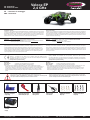 1
1
-
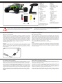 2
2
-
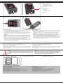 3
3
-
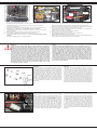 4
4
-
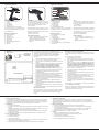 5
5
-
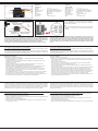 6
6
-
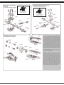 7
7
-
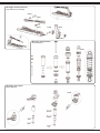 8
8
-
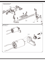 9
9
-
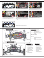 10
10
-
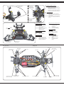 11
11
-
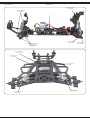 12
12
-
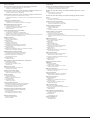 13
13
-
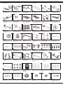 14
14
-
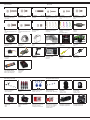 15
15
-
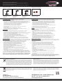 16
16


Jamara 053371 Manuale utente
- Categoria
- Giocattoli telecomandati
- Tipo
- Manuale utente
in altre lingue
- English: Jamara 053371 User manual
Documenti correlati
Altri documenti
-
Losi LOS03033T1 Manuale del proprietario
-
-
ProBoat PRB08037T1 Manuale del proprietario
-
 HYPE 018-1560 Manuale utente
-
-
Blade BLH8500 Manuale utente
-
-
Axial AXI03000T1 Manuale del proprietario
-
