
OPERATING INSTRUCTIONS
---------------------------------------------------------------------------------------------------------------------------------------------------------
MANUALE D’USO
---------------------------------------------------------------------------------------------------------------------------------------------------------
MANUEL D’INSTRUCTIONS
---------------------------------------------------------------------------------------------------------------------------------------------------------
BEDIENUNGSANWEISUNG
---------------------------------------------------------------------------------------------------------------------------------------------------------
РУКОВОДСТВО ПО ЭКСПЛУАТАЦИИ


OPERATING
INSTRUCTIONS


Pag. 1 MNVCNXPTH_1511_EN
INDEX
INTRODUCTION .................................................................................................................................................................... 2
Packing contents ........................................................................................................................................................................................ 2
Contents of this Manual .............................................................................................................................................................................. 2
Typographic conventions ............................................................................................................................................................................ 2
SAFETY RULES ..................................................................................................................................................................... 2
IDENTIFICATION DATA ........................................................................................................................................................ 3
DESCRIPTION OF NXPTH PAN & TILT MOTORS .............................................................................................................. 3
Features ..................................................................................................................................................................................................... 3
Appliances compatible with NXPTH ........................................................................................................................................................... 3
INSTALLATION ...................................................................................................................................................................... 3
Unpacking .................................................................................................................................................................................................. 3
Check of identification data ........................................................................................................................................................................ 3
ADJUSTMENT OF NXPTH PAN & TILT MOTORS .............................................................................................................. 4
CONNECTORS AND CONNECTIONS .................................................................................................................................. 5
Installation example .................................................................................................................................................................................... 5
Cables ........................................................................................................................................................................................................ 6
Pan & tilt connection to control units ........................................................................................................................................................... 6
Pan & tilt connection to DTRX3/DTMRX2 receiver ................................................................................................................................. 6
Preset connection to DTRX3 receiver .................................................................................................................................................... 7
SWITCHING ON AND OFF .................................................................................................................................................... 7
MAINTENANCE ..................................................................................................................................................................... 7
PROBLEM SOLUTION .......................................................................................................................................................... 7
SPECIFICATIONS .................................................................................................................................................................. 8
Mechanics .................................................................................................................................................................................................. 8
General ....................................................................................................................................................................................................... 8
Electric features .......................................................................................................................................................................................... 8
Dimensions ................................................................................................................................................................................................. 8
The manufacturer declines all responsibility for any damage caused by an improper use of the appliances mentioned
in this manual; furthermore, the manufacturer reserves the right to modify its contents without any prior notice.
The documentation contained in this manual has been collected with great care: the manufacturer, however, cannot
take any liability for its use. The same thing can be said for any person or company involved in the creation and
production of this manual.

Pag. 2 MNVCNXPTH_1511_EN
Introduction
Packing contents
1 pan & tilt motor NXPTH
1 bag with bolts and screws
1 instruction manual
After the delivery, check that the packing is not damaged and shows no evident signs of falls or abrasions. Should this
be so, contact immediately the supplier.
Check that the contents correspond to the above-mentioned list of materials.
Contents of this Manual
This manual describes NXPTH pan & tilt motors, together with their specific procedures of installation,
configuration and use. Read this manual carefully, in particular the chapter concerning the safety rules, before
installing and using the pan & tilt motor.
Typographic conventions
Different graphic symbols are used in this manual, the meaning of which is here described:
Hazard of electric shock; disconnect the power supply before proceeding, if not otherwise specified.
The operation is very important for the correct working of the system: read carefully the procedure indicated,
and carry it out according to the required modalities.
Description of system features: read carefully to understand the following phases.
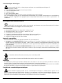
Safety rules
NXPTH pan & tilt motors comply with the normative laws in force at the time of editing of this manual,
concerning electric safety, electromagnetic compatibility and general requirements.
Anyway, in order to ensure the users (installer technician and operator), the following warnings are specified for
safety’s sake:
The appliance (and the complete system, which it belongs to) must be installed only by qualified technical staff
The appliance must be opened only by qualified technical staff. The tampering of the appliance may void the
guarantee terms.
Connect to a device corresponding to the specifications indicated on the data plate (see next chapter Identification
data)
Before any shifting or technical operations on the appliance, the cables connected to other appliances have been
removed
Do not use voltage cables showing wear or ageing, since they may seriously compromise the users’ safety
Do not use the appliance in the presence of inflammable substances
Do not allow children or people not familiar with the appliance to use it
Make sure the appliance is fixed in a solid and reliable way
The appliance is completely off-line only when the cables connected to other appliances have been removed
For after-sale service call only authorised technical staff
Keep this manual close to hand for any future reference

Pag. 3 MNVCNXPTH_1511_EN
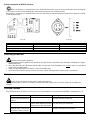
Identification data
On NXPTH pan & tilt motors there are two plates complying with EC specifications.
The first plate includes:
Model identification code (Extended bar code 3/9 )
Mains voltage (Volt)
Frequency (Hertz)
Power consumption (Watt)
The second plate shows the model serial number (Extended bar code 3/9)
When installing the appliance, check that the power supply specifications of the pan & tilt motor correspond to those
required. The use of improper appliances may seriously compromise the safety of the personnel and the installation.
Description of NXPTH pan & tilt motors
NXPTH unit is a vertical and horizontal pan & tilt motor, expressly projected for outdoor installations; both
models are equipped with the Preset function.
Features
Horizontal movement (Pan): from 0 to 350°. Speed: 5° per second
Vertical movement (Tilt): from 0 to 355°. Speed: 2,8° per second
Construction in Aisi 316 stainless steel
Completely sealed closing for indoor/outdoor operation
Operating temperature from -20°C to +55°C (from -4°F to 131°F)
PRESET for both models
Appliances compatible with NXPTH
The working of pan & Tilt motors is guaranteed only if connected to:
DTRX3 receiver driver: 17-function digital receiver, allowing the remote control of pan & tilt motors, wiper and
wash, and 4 auxiliary contacts. It can be individually addressed up to 999 units. It allows the management of max.
14 preset positions, which are recalled in the switching cycle by the patrol function.
DTMRX2/DTMRX224 minireceiver driver: 12-function digital receiver, allowing the control of pan & tilt motors
(horizontal and vertical, zoom lenses, autopan). It can be individually addressed up to 99 units.
Installation
The installation must be carried out only by qualified technical staff.
The following procedures must be carried out with power supply off, if not otherwise specified.
Unpacking
If the packing shows no relevant defects (due to falls or anomalous abrasions), check the material contained,
according to the list given at paragraph Packing contents chapter Introduction.
The packing materials can be completely recycled. The installer technician is required to dispose of them according to
the differentiated collecting modalities or ,anyway, according to the normative laws in force in the Country of use.
Check of identification data
Before installing the appliance, check that the material supplied corresponds to the specifications indicated on
the data plate, following the chapter Identification data. Do not carry out any modification or connections which are not
provided for in this manual: the use of improper appliances may seriously compromise the safety of the personnel and
the installation.

Pag. 4 MNVCNXPTH_1511_EN
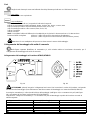
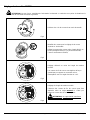
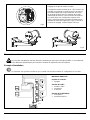
Adjustment of NXPTH pan & tilt motors
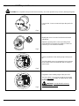
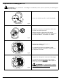
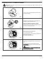
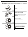
CAUTION: Do not position the pan & tilt motor manually, since this operation may seriously damage the gears.
Fig.1
Unscrew the 4 cover screws and open the pan & tilt
motor
Fig.2
Identify the cams for vertical and horizontal stroke
adjustment
Adjust the opening of the cams according to the
angle wished, by forcing them slightly (no tools are
necessary, it is a friction movement)
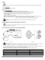
Fig.3
Factory regulation of the rotating angle of the pan &
tilt:
The limit switch cams are symmetrical set in respect
to the center of the microswitches with an angle of
about A=90°.
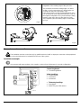
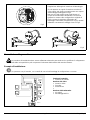
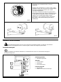
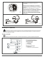
Fig.4
Regulation of the rotating angle of the pan & tilt:
The limit switch cams can be moved each one with
an angle maximum
B=180° in respect to the center
of the microswitches.
CAUTION: An angle B>180° seriously
damage the potentiometer!

Pag. 5 MNVCNXPTH_1511_EN
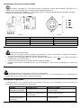
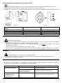
Fig.5
Regulation of the rotating angle of the pan & tilt:
The maximum reachable rotating angle is of about
A=350°. For this reason there is a “dead angle” not
covered from the pan & tilt visible in Fig.5.
If this “dead angle” is inside the desired field of vision
it is necessary to move again the limit switch cams on
the original configuration of Fig.3 and rotate the fixing
position of the pan & tilt on its bracket (see Fig.6).
Then regulate again the rotating angle as described
in Fig.4.
Fig.6
Connectors and connections
The installation must be carried out only by qualified technical staff: an improper connection of the peripheral
units may cause the keyboard to be isolated from the rest of the system.
Installation example
One operator with more monitors, who controls a series of pan & tilt motors in cascade configuration.
MATERIAL USED
Control keyboard:
1 control keyboard
Video handling:
1 video matrix
2 monitors
4 cameras
Telemetry handling:
4 receivers
4 NXPTH pan & tilt motors
Video matri
x
Keyboard

Pag. 6 MNVCNXPTH_1511_EN
Cables
Different types of stroke have been used in the previous examples, in order to indicate cables with different
functions:
video cable:
RG 59 coaxial cable or equivalent cable
multipolar cable:
Fix the final numbers of wires according to the following directions:
6 wires for the motion of the positioning device: right, left, up, down, autopan, common, ground
6 wires for the control of polarity reversal lenses (zoom, focus, iris)
4 wires for the control of common wire lenses (zoom, focus, iris)
2 wires for the auxiliary device
4 wires for the preset function
Note: We recommend the use of different multipolar cables for high tension and low tension functions.
Minimum section area recommended: 0.56 mm.² (AWG 20) for high tension wires (positioning device)
0.34 mm.² (AWG 22) for low tension wires (lens, auxiliary device, preset)
Warning! The preset multipolar cable must not be the same used for the pan & tilt motor.
Pan & tilt connection to control units
In the following drawing, identify the terminal block J1 in the horizontal movement circuit for the pan & tilt
connection to the control units:
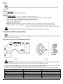
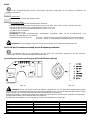
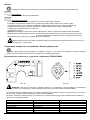
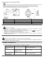
Pan & tilt connection to DTRX3/DTMRX2 receiver
Fig. 1A Fig. 1B
WARNING: before the connection, make sure that the output voltage of the receiver corresponds to pan & tilt
voltage (refer to the identification data of the pan & tilt motor and to DTRX3/DTMRX2 manual).
Where to operate: J1 terminal block in the lower printed circuit of the pan & tilt motor (see drawing 1A) or 6+1 poles
connector (see drawing 1B), terminal block of the receiver (see DTRX3/DTMRX2 manual)
Adjustments: connect the terminal block J1 of the pan & tilt motor to that of the receiver according to the following table
Connection to the receiver Terminal block J1 (Pan & Tilt) 6+1 poles connector
COM Com 1
DOWN Down 2
UP Up 3
RIGH Right 4
LEFT Left 5
earth

Pag. 7 MNVCNXPTH_1511_EN
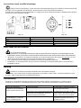
Preset connection to DTRX3 receiver
Where to operate: J1 terminal block in the horizontal movement circuit of the pan & tilt motor (see drawing 2A)
or 3+1 poles connector (see drawing 2B), terminal block of preset (see DTRX3 manual)
Adjustments: connect the J1 terminal block of the pan & tilt motor to the terminal block of the DTRX3 preset according
to the following table:
Fig. 2A Fig. 2B
Connection to DTRX3 receiver Terminal block J1 on Pan & Tilt 3+1 poles connector
Vcc Vcc 1
Pan Pan 2
Tilt Tilt 3
Gnd Gnd
Switching on and off
Before connecting the appliance:
check that the material supplied corresponds to the specifications indicated on the data plate, following the chapter
Identification data
check that NXPTH pan & tilt motor and the other components of the installation are closed
in order to avoid direct
contact with energized parts.
make sure that all the parts are fixed in a solid and reliable way
check that the electrical capacity and the connection cables will support the system power consumption
Maintenance
NXPTHpan & tilt motors do not need a special maintenance.
Make sure they always rest on a solid base, and that the power supply and connection cables do not hinder the
operator.
Problem solution
Even if NXPTH pan & tilt motors are very easy to use, some problems may arise during installation, configuration or use.
Problem Possible cause Remedy
The receiver is working, but
the pan & tilt motor does not
respond
Incorrect connections Check the connections between the pan &
tilt motor and the control unit
The voltage supplied by the
control unit is different from that
required by the pan & tilt motor
Check the identification data of the control
unit and of the pan & tilt motor
The pan & tilt motor
responds to the controls but
the PRESET does not work
Incorrect connections Check the connections between the pan &
tilt motor and the DTRX3 receiver

Pag. 8 MNVCNXPTH_1511_EN
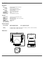
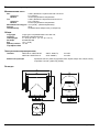
Specifications
Mechanics
Pan 0-355° horizontal plane movement
Speed 5° per second
Torque 35 Nm at specified voltage
Tilt 0-355° vertical plane movement
Speed 2,8° per second
Torque 63 Nm at specified voltage
Maximum load 40 Kg (88 lb) (balanced)
Protection IP 67
Potentiometer Linear Multiturns (10 turns)
General
Construction carpentry in Aisi 316 stainless steel
Finish external polishing
Temperature from -20°C to +55°C (from -4°F to 131°F)
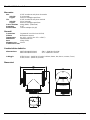
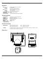
Dimensions 164x250x280 mm
Weight 15 Kg (33 lb)
Cable diameter 10 mm
EAC certification
Electric features
Power Supply NXPTH210/NXPTH210C 230 V~ 50/60 Hz 13+13 W
NXPTH211/NXPTH211C 24 V~ 50/60 Hz 13+13 W
Wiring 6 cables 0.56mm.² (AWG 20) (Functions: left, right, up, down, common and earth).
4 cables 0.34mm.² (AWG 22) (Preset)
Dimensions

MANUALE
D’USO


Pag. 1 MNVCNXPTH_1511_IT
INDICE
INTRODUZIONE ..................................................................................................................................................................... 2
Contenuto dell’imballo ................................................................................................................................................................................ 2
Cosa contiene questo manuale .................................................................................................................................................................. 2
Convenzioni tipografiche ............................................................................................................................................................................ 2
NORME DI SICUREZZA ........................................................................................................................................................ 2
DATI DI MARCATURA .......................................................................................................................................................... 3
DESCRIZIONE DEI BRANDEGGI NXPTH ............................................................................................................................ 3
Caratteristiche ............................................................................................................................................................................................ 3
Apparecchi compatibili ................................................................................................................................................................................ 3
INSTALLAZIONE ................................................................................................................................................................... 3
Apertura dell’imballaggio ............................................................................................................................................................................ 3
Controllo della marcatura ........................................................................................................................................................................... 3
REGOLAZIONE DEI BRANDEGGI NXPTH .......................................................................................................................... 4
CONNETTORI E COLLEGAMENTI ....................................................................................................................................... 5
Esempio di installazione ............................................................................................................................................................................. 5
Cavi ............................................................................................................................................................................................................ 6
Collegamento del brandeggio alle unità di comando .................................................................................................................................. 6
Collegamento del brandeggio al ricevitore DTRX3/DTMRX2 ................................................................................................................. 6
Collegamento del Preset al ricevitore DTRX3 ........................................................................................................................................ 7
ACCENSIONE E SPEGNIMENTO ......................................................................................................................................... 7
MANUTENZIONE ................................................................................................................................................................... 7
RISOLUZIONE DI PROBLEMI ............................................................................................................................................... 7
CARATTERISTICHE TECNICHE .......................................................................................................................................... 8
Meccanica .................................................................................................................................................................................................. 8
Generali ...................................................................................................................................................................................................... 8
Caratteristiche elettriche ............................................................................................................................................................................. 8
Dimensioni .................................................................................................................................................................................................. 8
Il produttore declina ogni responsabilità per eventuali danni derivanti da un uso improprio delle apparecchiature
menzionate in questo manuale; si riserva inoltre il diritto di modificarne il contenuto senza preavviso.
Ogni cura é stata posta nella raccolta e nella verifica della documentazione contenuta in questo manuale: tuttavia il
produttore non può assumersi alcuna responsabilità derivante dall’utilizzo della stessa. Lo stesso dicasi per ogni
persona o società coinvolta nella creazione e nella produzione di questo manuale.

Pag. 2 MNVCNXPTH_1511_IT
Introduzione
Contenuto dell’imballo
1 brandeggio NXPTH
1 sacchetto dotazione viteria
1 manuale d’uso
Alla consegna del prodotto verificare che l’imballo sia integro e non abbia segni evidenti di cadute o abrasioni. In caso
di evidenti segni di danno all’imballo contattare immediatamente il fornitore.
Controllare che il contenuto sia rispondente alla lista del materiale sopra indicata.
Cosa contiene questo manuale
In questo manuale sono descritti i brandeggi della serie NXPTH, con le particolari procedure di installazione,
configurazione e utilizzo. E’ necessario leggere attentamente questo manuale, in particolar modo il capitolo
concernente le norme di sicurezza, prima di installare ed utilizzare il brandeggio.
Convenzioni tipografiche
Nel presente manuale si fa uso di diversi simboli grafici, il cui significato è riassunto di seguito:
Rischio di scariche elettriche; togliere l’alimentazione prima di procedere con le operazioni, se non é
espressamente indicato il contrario.
L’operazione é molto importante per il corretto funzionamento del sistema: si prega di leggere attentamente la
procedura indicata, ed eseguirla secondo le modalità previste.
Descrizione delle caratteristiche del sistema: si consiglia di leggere attentamente per comprendere le fasi
successive.
Norme di sicurezza
I brandeggi NXPTH sono conformi alle normative vigenti all’atto della pubblicazione del presente manuale per
quanto concerne la sicurezza elettrica, la compatibilità elettromagnetica ed i requisiti generali.
Si desidera tuttavia garantire gli utilizzatori (tecnico installatore e operatore) specificando alcune avvertenze per
operare nella massima sicurezza:
L’installazione dell’apparecchio (e dell’intero impianto di cui esso fa parte) deve essere effettuata da personale
tecnico adeguatamente qualificato
L’apparecchio deve essere aperto soltanto da personale tecnico qualificato. La manomissione dell’apparecchio fa
decadere i termini di garanzia
Collegare ad un dispositivo corrispondente come indicato sulle etichette di marcatura (vedere il successivo capitolo
Dati di marcatura)
Prima di spostare o effettuare interventi tecnici sull’apparecchio, disinserire i cavi di collegamento con altri
dispositivi
Non utilizzare cavi di tensione con segni di usura o invecchiamento, in quanto rappresentano un grave pericolo per
l’incolumità degli utilizzatori
Non utilizzare l’apparecchio in presenza di sostanze infiammabili
Non permettere l’uso dell’apparecchio a bambini o incapaci
Accertarsi che l’apparecchio sia fissato in maniera solida e affidabile
L’apparecchio si considera disattivato soltanto quando i cavi di collegamento con altri dispositivi sono stati rimossi
Per l’assistenza tecnica rivolgersi esclusivamente al personale tecnico autorizzato
Conservare con cura il presente manuale per ogni futura consultazione

Pag. 3 MNVCNXPTH_1511_IT
Dati di marcatura
Sui brandeggi NXPTH sono riportate due etichette conformi alla marcatura CE.
La prima etichetta contiene:
Codice di identificazione del modello (Codice a barre Extended 3/9 )
Tensione di alimentazione (Volt)
Frequenza (Hertz)
Consumo (Watt)
La seconda etichetta indica il numero di serie del modello (codice a barre Extended 3/9)
All’atto dell’installazione controllare se le caratteristiche di alimentazione del brandeggio corrispondono a quelle
richieste. L’uso di apparecchi non idonei può portare a gravi pericoli per la sicurezza del personale e dell’impianto.
Descrizione dei brandeggi NXPTH
L’unità NXPTH è un brandeggio verticale e orizzontale appositamente studiato per essere utilizzato in
ambienti esterni, entrambi i modelli sono dotati di funzione Preset.
Caratteristiche
Movimento sul piano orizzontale (Pan): da 0 a 355°. Velocità: 5° al secondo
Movimento sul piano verticale (Tilt): da 0 a 355°. Velocità: 2,8° al secondo
Costruzione in acciaio inox Aisi 316
Chiusura completamente sigillata per operare sia in ambiente interno che esterno
Temperatura di funzionamento da -20°C a +55°C
PRESET per entrambe le versioni
Apparecchi compatibili
La funzionalita’ dei brandeggi e’ garantita solo se collegati a :
Ricevitore di comandi DTRX3: ricevitore digitale a 17 funzioni, consente il controllo a distanza di un brandeggio
motorizzato, di lavavetri e pompa, e di 4 contatti ausiliari. È indirizzabile singolarmente fino a 999 unità. Permette la
gestione di max 14 posizioni di preset, richiamabili in ciclata con la funzione patrol.
Miniricevitore di comandi DTMRX2/DTMRX224: ricevitore digitale a 12 funzioni, consente il controllo di base di
un brandeggio motorizzato (orizzontale e verticale, ottiche, autopan, ausiliare). Indirizzabile singolarmente fino a
99 unità.
Installazione
La fase di installazione deve essere effettuata solo da personale tecnico qualificato.
Le seguenti procedure sono da effettuare in assenza di alimentazione, se non diversamente indicato.
Apertura dell’imballaggio
Se l’imballo non presenta evidenti difetti (dovuti a cadute o abrasioni anomale), procedere al controllo del materiale in
esso contenuto, secondo la lista fornita al paragrafo Contenuto dell’imballo al capitolo Introduzione.
I materiali d’imballo sono costituiti interamente da materiale riciclabile. Sarà cura del tecnico installatore smaltirli
secondo le modalità di raccolta differenziata o comunque secondo le norme vigenti nel Paese di utilizzo.
Controllo della marcatura
Prima di procedere con l’installazione controllare se il materiale fornito corrisponde alle specifiche richieste,
esaminando le etichette di marcatura, secondo quanto descritto al capitolo Dati di marcatura.
Non effettuare per nessun motivo alterazioni o collegamenti non previsti in questo manuale: l’uso di apparecchi non
idonei può portare a gravi pericoli per la sicurezza del personale e dell’impianto.

Pag. 4 MNVCNXPTH_1511_IT
Regolazione dei brandeggi NXPTH
ATTENZIONE: Non posizionare il brandeggio manualmente poichè questa operazione può danneggiare
seriamente gli ingranaggi.
Fig.1
Svitare le 4 viti del coperchio e aprire il brandeggio
Fig.2
Identificare le camme per la regolazione della corsa
verticale e di quella orizzontale
Regolare l’ampiezza di apertura delle camme
secondo l’angolo desiderato, forzandole leggermente
(non servono attrezzi, il movimento è a frizione)
Fig.3
Regolazione di fabbrica dell’angolo di
rotazione del brandeggio:
Le camme di finecorsa sono regolate in modo
simmetrico rispetto al centro dei microswitches con
un angolo di circa A=90°.
Fig.4
Regolazione dell’angolo di rotazione del brandeggio:
Le camme di finecorsa possono essere spostate
ognuna con un angolo massimo
B=180° rispetto al
centro dei microswitches.
ATTENZIONE: Un angolo B>180° comporta
un danneggiamento del potenziometro!

Pag. 5 MNVCNXPTH_1511_IT
Fig.5
Regolazione dell’angolo di rotazione del brandeggio:
Si può ottenere un angolo di rotazione massimo di
circa A=350°. Ne risulta un angolo morto non coperto
dal brandeggio tratteggiato in Fig.5.
Nel caso che tale angolo morto risulti interno al
campo di visualizzazione desiderato è necessario
riportare le camme nella configurazione originale di
Fig.3 e ruotare la posizione di fissaggio del
brandeggio sulla staffa di supporto (es. Fig.6). Quindi
effettuare nuovamente il settaggio come in Fig.4.
Fig.6
Connettori e collegamenti
La procedura di installazione deve essere effettuata soltanto da personale tecnico qualificato: il collegamento
non corretto delle varie periferiche può comportare l’isolamento della tastiera dal resto del sistema.
Esempio di installazione
Un operatore con più monitor, con controllo di una serie di brandeggi in configurazione a cascata.
MATERIALE IMPIEGATO
Tastiera di controllo:
1 tastiera di controllo
Gestione del video:
1 matrice video
2 monitor
4 telecamere
Gestione della telemetria:
4 ricevitori
4 brandeggi NXPTH
Matrice video
Tastiera

Pag. 6 MNVCNXPTH_1511_IT
Cavi
Negli schemi d’esempio sono stati utilizzati diversi tipi di tratto per indicare cavi di diversa funzione:
cavo video:
coassiale RG 59 o cavo equivalente.
cavo multipolare:
Stabilire il numero finale di cavi, seguendo le indicazioni seguenti:
6 fili per la movimentazione del brandeggio: destra, sinistra, alto, basso, comune, terra
6 fili di controllo per ottiche ad inversione di polarità (zoom, focus, iris)
4 fili di controllo per ottiche a filo comune (zoom, focus, iris)
2 fili per l’ ausiliare
4 fili per il Preset
Nota: è consigliato l’utilizzo di differenti cavi multipolari per le funzioni in bassa tensione ed in alta tensione.
Sezione minima consigliata: 0,56 mm.² (AWG 20) per fili in alta tensione (brandeggio)
0,34 mm.² (AWG 22) per fili in bassa tensione (ottica, ausiliare, preset)
Attenzione! Il cavo multipolare del preset non deve essere lo stesso del brandeggio.
Collegamento del brandeggio alle unità di comando
Nella figura seguente identificare la morsettiera J1, sulla scheda relativa al movimento orizzontale, per il
collegamento del brandeggio alle unità di comando:
Collegamento del brandeggio al ricevitore DTRX3/DTMRX2
Fig. 1A Fig. 1B
ATTENZIONE: prima di eseguire i collegamenti assicurarsi che la tensione in uscita dal ricevitore corrisponda
alla tensione del brandeggio (Fare riferimento ai dati di marcatura del brandeggio e al manuale DTRX3/DTMRX2).
Dove Agire: morsettiera J1 sulla scheda inferiore del brandeggio (vedi figura 1A) o connettore 6+1 poli (vedi figura
1B), morsettiera del ricevitore (vedi manuale DTRX3/DTMRX2)
Impostazioni: collegare la morsettiera J1 o il connettore 6+1 poli del brandeggio a quella del ricevitore secondo la
tabella seguente
Collegamento al ricevitore Morsetto J1 (brandeggio) Connettore 6+1 poli
COM Com 1
DOWN Down 2
UP Up 3
RIGHT Right 4
LEFT Left 5
EARTH
La pagina si sta caricando...
La pagina si sta caricando...
La pagina si sta caricando...
La pagina si sta caricando...
La pagina si sta caricando...
La pagina si sta caricando...
La pagina si sta caricando...
La pagina si sta caricando...
La pagina si sta caricando...
La pagina si sta caricando...
La pagina si sta caricando...
La pagina si sta caricando...
La pagina si sta caricando...
La pagina si sta caricando...
La pagina si sta caricando...
La pagina si sta caricando...
La pagina si sta caricando...
La pagina si sta caricando...
La pagina si sta caricando...
La pagina si sta caricando...
La pagina si sta caricando...
La pagina si sta caricando...
La pagina si sta caricando...
La pagina si sta caricando...
La pagina si sta caricando...
La pagina si sta caricando...
La pagina si sta caricando...
La pagina si sta caricando...
La pagina si sta caricando...
La pagina si sta caricando...
La pagina si sta caricando...
La pagina si sta caricando...
La pagina si sta caricando...
La pagina si sta caricando...
-
 1
1
-
 2
2
-
 3
3
-
 4
4
-
 5
5
-
 6
6
-
 7
7
-
 8
8
-
 9
9
-
 10
10
-
 11
11
-
 12
12
-
 13
13
-
 14
14
-
 15
15
-
 16
16
-
 17
17
-
 18
18
-
 19
19
-
 20
20
-
 21
21
-
 22
22
-
 23
23
-
 24
24
-
 25
25
-
 26
26
-
 27
27
-
 28
28
-
 29
29
-
 30
30
-
 31
31
-
 32
32
-
 33
33
-
 34
34
-
 35
35
-
 36
36
-
 37
37
-
 38
38
-
 39
39
-
 40
40
-
 41
41
-
 42
42
-
 43
43
-
 44
44
-
 45
45
-
 46
46
-
 47
47
-
 48
48
-
 49
49
-
 50
50
-
 51
51
-
 52
52
-
 53
53
-
 54
54


Videotec NXPTH Manuale utente
- Tipo
- Manuale utente
in altre lingue
- français: Videotec NXPTH Manuel utilisateur
- Deutsch: Videotec NXPTH Benutzerhandbuch
Documenti correlati
-
Videotec PTH300 Manuale utente
-
-
-
-
-
-
-
-
-