
D
D
T
T
R
R
X
X
3
3
-
-
D
D
T
T
R
R
X
X
3
3
2
2
4
4
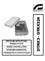
OPERATING INSTRUCTIONS
---------------------------------------------------------------------------------------------------------------------------------------------------------
MANUALE D’USO
---------------------------------------------------------------------------------------------------------------------------------------------------------
MANUEL D’INSTRUCTIONS
---------------------------------------------------------------------------------------------------------------------------------------------------------
BEDIENUNGSANWEISUNG
---------------------------------------------------------------------------------------------------------------------------------------------------------
РУКОВОДСТВО ПО ЭКСПЛУАТАЦИИ


D
D
T
T
R
R
X
X
3
3
-
-
D
D
T
T
R
R
X
X
3
3
2
2
4
4
OPERATING
INSTRUCTIONS


Pag. 1 MNVCDTRX301_1623_EN
INDEX
INDEX ..................................................................................................................................................................................... 1
INTRODUCTION .................................................................................................................................................................... 3
Contents of the packaging .........................................................................................................................................................................3
Contents of this manual .............................................................................................................................................................................3
Typographical conventions .........................................................................................................................................................................3
SAFETY RULES ..................................................................................................................................................................... 3
OPERATING DATA ON THE RATING PLATE ...................................................................................................................... 4
DESCRIPTION OF THE DTRX3 RECEIVER ......................................................................................................................... 4
Features .....................................................................................................................................................................................................4
Compatible devices for the use with the DTRX3 receiver ..........................................................................................................................5
Installation examples ..................................................................................................................................................................................5
Cables ........................................................................................................................................................................................................6
INSTALLATION ...................................................................................................................................................................... 7
Unpacking ..................................................................................................................................................................................................7
Control of the operating data on the rating plate ........................................................................................................................................7
Dip-switches and configuration jumpers.....................................................................................................................................................7
CONFIGURATION OF THE RECEIVER ................................................................................................................................ 8
Identification number of the receiver ..........................................................................................................................................................8
DTRX3 receiving mode ..............................................................................................................................................................................8
Setting of RS485 line load ..........................................................................................................................................................................8
Type of lenses used ...................................................................................................................................................................................9
Setting the protocol and the communication speed ...................................................................................................................................9
Control voltage of the positioning device and the wiper ...........................................................................................................................10
AUX3 / AUX4 auxiliary devices ................................................................................................................................................................10
Connection with the control unit ...............................................................................................................................................................10
Connection with the RS485 line ...............................................................................................................................................................11
Connecting more than one receiver in cascade (point-to-point connection) ........................................................................................11
More than one receiver per line, connection with twisted pair cable (multipoint connection) ...............................................................12
Mixed configurations (point-to-point / multi-point) ................................................................................................................................13
Connection with the Current Loop line .....................................................................................................................................................13
Connection with the RS232 line ...............................................................................................................................................................14
Adjusting the voltage of the optics controls ..............................................................................................................................................15
Connecting the pan&tilt and optics cables ...............................................................................................................................................15
SETTING THE RECEIVER FOR PRESET FUNCTIONS ..................................................................................................... 15
TESTING THE DTRX3 RECEIVER ...................................................................................................................................... 16
USE OF THE ALARM CONTACTS ...................................................................................................................................... 17
Operation mode of AUX4 .........................................................................................................................................................................17
AUXILIARIES AUX1 AND AUX2 .......................................................................................................................................... 17
LOCAL KEYS FOR P&T MOTOR MOVEMENT.................................................................................................................. 17
PELCO D CONTROLS RECOGNISED BY THE DTRX3 RECEIVER ................................................................................. 18
SWITCHING ON AND SWITCHING OFF ............................................................................................................................ 19
MAINTENANCE .................................................................................................................................................................... 19

Pag. 2 MNVCDTRX301_1623_EN
TROUBLESHOOTING ......................................................................................................................................................... 19
DIP SWITCH SW4 AND SW6 CONFIGURATION TABLES ................................................................................................ 20
TECHNICAL FEATURES ..................................................................................................................................................... 20
DESCRIPTION OF THE DTRX324 RECEIVER ................................................................................................................... 21
Compatible devices for the use with the DTRX324 receiver ....................................................................................................................21
TECHNICAL FEATURES ..................................................................................................................................................... 22
The manufacturer assumes no responsibility for possible damages resulting from an improper use of the devices
mentioned in this manual; moreover he reserves the right to change the contents of the present manual without notice.
The documentation contained in this manual has been gathered and examined with great care; nevertheless the
manufacturer can not assume any responsibility resulting from the use of such documentation. The same is valid for
any other person or society involved in the creation and in the production of the present manual.

Pag. 3 MNVCDTRX301_1623_EN
Introduction
Contents of the packaging
• 1 DTRX3 receiver
• 1 user’s manual
• 2 PG11 blanking caps
• 4 wall mounts with relevant fastening screws
On delivery, please make sure that the packaging does not present damages or evident signs of falls or scratches. In
case of evident damages, contact immediately the supplier.
Please, make sure that the contents correspond to the components list mentioned above.
Contents of this manual
This manual contains the description of the DTRX3 receiver, with the relevant installation, configuration and use
procedures. Before installing and using the receiver it is necessary to read carefully the present manual, in
particular the section concerning the safety rules.
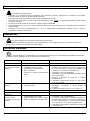
Typographical conventions
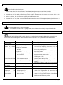
The following section illustrates the meaning of the several graphic symbols used in the present manual:
Risk of electric shock; before proceeding with the operations, if not otherwise stated, disconnect the unit.
The operation is very important for the correct functioning of the system: please read carefully the procedure
indicated and carry it out according to the prescribed specifications.
Description of the system features; we recommend reading carefully the sections marked with this symbol in
order to understand the phases which follow.
Safety rules
The DTRX3 receiver complies with the rules in force at the time of publication of the present manual as regards
the electric safety, the electromagnetic compatibility and the other general requirements.
Nevertheless we would like to assure the users (installer and operator) illustrating some measures to be adopted in
order to guarantee the maximum safety:
• The installation of the unit (and of the whole plant of which this unit is part) must be carried out by adequately skilled
technical personnel
• The unit must be opened only by skilled technical personnel. The warranty limits does not cover damages resulting
from an improper use of the unit
• Connect the unit to a power supply corresponding to the one indicated on the rating plate (see next section
Operating data on the rating plate)
• The outlet must be adequately grounded according to the rules in force
• Before moving or carrying out technical operations on the unit, disconnect it
• Do not use worn or damaged power cords, since they represent a serious risk for the user’s safety
• Do not use the device in areas containing inflammable substances
• Equipment must be opened only by skilled technical personnel in a non explosive atmosphere. The warranty limits
does not cover damages resulting from an improper use of the unit.
• Do not allow children or unskilled persons to use the unit
• Make sure that the unit is fixed securely and firmly
• The unit is considered off-line only when the power supply is disconnected and the cables aimed to connect the unit
with other devices have been removed
• Before feeding the DTRX3 a protection device must be installed in the building electrical network
• For the after-sales service, please contact exclusively the authorised technical personnel
• Keep the present manual with care for any future consultation

Pag. 4 MNVCDTRX301_1623_EN
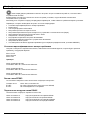
Operating data on the rating plate
The DTRX3 receiver is supplied with two rating plates in conformity with the EC standards.
The first plate contains:
• Model identification code (Extended 3/9 bar code)
• Power supply (Volt)
• Frequency (Hertz)
• Consumption (Watt)
The second plate indicates the serial number of the model (Extended 3/9 bar code).
During the installation phase, make sure that the power supply features of the receiver correspond to the
characteristics required. The use of unsuitable devices can lead to serious risks for the safety of the personnel and the
security of the plant.
Description of the DTRX3 receiver
The DTRX3 receiver is a microprocessor-based command receiver for the remote control of positioning
devices, motorised lenses, wiper, washer and auxiliary functions.
Features
• 17 functions: UP, DOWN, LEFT, RIGHT, AUTO, WASHER, WIPER, ZOOM TELE, ZOOM WIDE, FOCUS NEAR,
FOCUS FAR, IRIS OPEN, IRIS CLOSE, AUX1, AUX2, AUX3, AUX4
• Power supplied to the camera: 12 V
= max 350mA (AUX1) and 24 V~ max 180mA (AUX2)
• 2 dry contacts 1 A 230 V~ or 1A 24 V~
(AUX3 and AUX4)
• 999 selectable addresses through dip switches or rotative switches
• Serial input selectable between RS-232 / Current Loop / RS485
• Selectable communication speed (38400 / 19200 / 9600 / 4800 / 2400 / 1200 / 300 Baud)
• RS232, RS485 and Current Loop repeater for in-line configuration
• Possibility of using both polarity inversion lenses and common wire lenses
• Led indicating power supplied to the unit
• Led indicating active function
• EEPROM for the storage of active options
• 16 bit microcontroller with re-programmable Flash memory
• Trimmer for the adjustment of the lens voltage (from 3 V
= up to 12 V=)
• PRESET / SCAN / PATROL functions with an automatic recognition of the existing functions
• Possibility to memorise up to 14 PRESET functions (Pan &Tilt motor, lens) with standard Videotec protocol and 40
positions with MACRO protocol and Pelco D protocol (DCJ, DCT, DCIR keyboards)
• 4 alarm contacts set as N.O. or N.C.

Pag. 5 MNVCDTRX301_1623_EN
Compatible devices for the use with the DTRX3 receiver
WARNING! In case of using the DTRX324, refer to the paragraph 17. Compatible devices for the use with the
DTRX324 receiver.
• Control keyboards: DCT, DCJ, DCTEL, DCIR, DCS3, DCS2, DCMT8
• Pan & Tilt motors: PTH310/PTH310P, PTH311/PTH311P, PTH910/PTH910P, PTH911/PTH911P, NXPTH210,
NXPTH211C
• DCMX: communications controller
• DCRE485: serial data distributor
Read the instruction manuals for the correct use of the above mentioned devices.
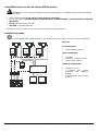
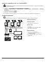
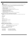
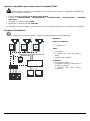
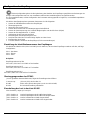
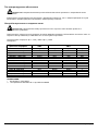
Installation examples
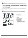
A single operator with several monitors for the control of a set of positioning devices in mixed configuration:
DEVICES:
Control keyboard:
• 1 DCS3 control keyboard
Video management:
• 2 monitors
• 3 cameras (+1 OEM receiver)
• 1 video matrix SW328
Telemetry management:
• 3 DTRX3 receivers
• 3 PTH910P
P&T motors
(PTH911P with DTRX324
receiver)
•
1 OEM receiver (with camera
included)
R1
R2
R3
M1
OEM
K1

Pag. 6 MNVCDTRX301_1623_EN
Cables
Different types of stroke have been used in the example, in order to indicate cables with different functions:
phone cable:
1,5 m equipped with the keyboard.
video cable:
RG 59 coaxial cable or equivalent cable.
For long distances a video transmission system on twisted pair is suggested.
multipolar cable:
each control function of the positioning device is activated /deactivated by a relay positioned inside the receiver.
Choose the final numbers of wires according to the following directions:
• 7 wires for the motion of the positioning device (230 V~ or 24 V~): right, left, up, down, autopan, common, ground
(only for 230 V~)
• 6 wires for the control of polarity reversal lenses (zoom, focus, iris)
• 4 wires for the control of common wire lenses (zoom, focus, iris)
• 7 wires for the preset control: 5 wires connected to the reference potentiometers, +5 V
= and ground
• 4 wires for the wiper
• 3 wires for the washer
• 2 wires for each auxiliary device used
• 3 wires for the power supply cable
Note: We recommend using different multipolar cables for high tension and low tension functions.
Minimum section area recommended: 0,56 mm² (AWG 20) for high tension wires
(positioning device, wiper, washer)
0,34 mm² (AWG 22) for low tension wires
(lens, auxiliary devices, preset)
0,75 mm² (AWG18) for power supply cable of DTRX3
cable for the digital reception/transmission of commands:
• 2 wires for the reception from the control unit (twisted telephone pair, section 0.22 mm.² AWG 24)
• 2 wires for the possible transmission to the next cascade-connected receiver (twisted telephone pair, section 0.22
mm² AWG 24)
Note: Maximum distance for the connection: about 15 m in RS232; 1500 m in Current Loop; 1200m in RS485.
WARNING! If many receivers are cascade-connected, it is necessary to use two separated cables for the
digital reception and transmittion of commands (do not use multicouple cable) between the receivers.

Pag. 7 MNVCDTRX301_1623_EN
Installation
The unit must be installed exclusively by skilled technical personnel.
Before carrying out the following operations, if not otherwise stated, always disconnect the unit.
Unpacking
If the packaging does not present evident faults (due to falls or anomalous scratches), make sure that its contents correspond to
the list of items contained in paragraph Contents of the packaging, in section Introduction.
The container is completely made of recyclable material. The installer will take care to dispose it according to the
recycling programs or, in any case, according to the rules in force in the country of destination.
Control of the operating data on the rating plate
Before installing the unit, control if the goods supplied correspond to the required specifications by examining
the rating plates, according to the section Operating data on the rating plate. Never make alterations or connections not
provided for in the present manual: the use of unsuitable devices can lead to serious risks for the safety of the
personnel and the security of the plant.
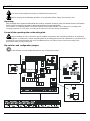
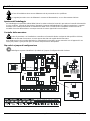
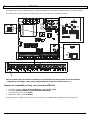
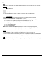
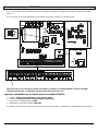
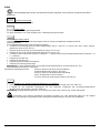
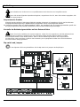
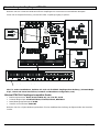
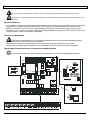
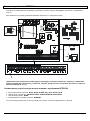
Dip-switches and configuration jumpers
In the following scheme identify Dip switches and configuration jumpers :
LD1

Pag. 8 MNVCDTRX301_1623_EN
Configuration of the receiver
The receiver configuration phase allows to optimise its functioning according to the particular requirements of
the plant. The unit must be configured exclusively during the installation phase and by an installer.
We recommend proceeding with the configuration of the parameters in a systematic way in order to avoid installation
troubles.
The parameters to set during the configuration phase are the following:
• Identification number of the receiver
• Receiving mode setup
• Type of lenses used
• Protocol and communication speed
• Control voltage of the positioning device and the wiper
• AUX3 / AUX4 auxiliary devices
• Connection with the control unit
• Control voltage of lenses
• Connection of the positioning device and the lenses cables
• Alarms setting
• Test of the receiver active functions (for PRESET operations)
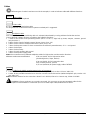
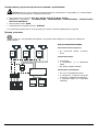
Identification number of the receiver
Configure the SW1, SW2 and SW3 rotative-switches according to the address to assign to the receiver as follows:
SW1:hundred
SW2: ten
SW3: unit
Examples:
Receiver address n.359
Set SW1 to 3, SW2 to 5 and SW3 to 9
Receiver address n.27
Set SW1 to 0, SW2 to 2 and Sw3 to 7
Receiver address n.4
Set SW1 to 0, SW2 to 0 and SW3 to 4
DTRX3 receiving mode
According to the communication type to set follow the following settings:
Current Loop: JP2 and JP3 to CL position
RS485: see below (setting of RS485 line load)
RS232: No setting needed
Setting of RS485 line load
Jumpers: JP5 and JP6
JP5 in A position: load inserted in RS485 transmission.
JP5 in B position: no load inserted in RS485 transmission.
JP6 in A position: load inserted in RS485 reception.
JP6 in B position: no load inserted in RS485 reception.

Pag. 9 MNVCDTRX301_1623_EN
Type of lenses used
WARNING! An inaccurate setup of this parameters can cause damages to the lenses!
The DTRX3 receiver can control both polarity inversion lenses and common wire lenses. In case of common wire
lenses connect the common wire to FOCUS-.
Setting the protocol and the communication speed
WARNING! An inaccurate protocol and/or communication speed selection can cause damages to the receiver.
The DTRX3 receiver can be used in digital transmission systems and it can communicate with a speed from 300 to
38400 baud, depending on the used protocol.
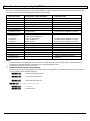
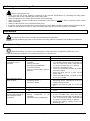
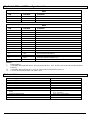
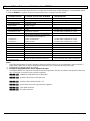
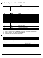
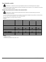
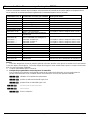
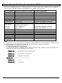
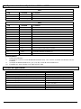
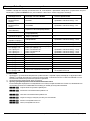
Dip switch: switches 1, 2 and 8 of SW4 and 1 of SW6.
Settings:
Protocol - Baud rate
SW6
SW4
Dip 1
Dip 1
Dip 2
Dip 8
Videotec - 300 baud
OFF
ON
OFF
ON
Videotec - 1200 baud
OFF
OFF
ON
ON
Videotec - 9600 baud*
OFF
OFF
OFF
ON
Videotec - 19200 baud
OFF
ON
ON
ON
MACRO - 1200 baud
OFF
OFF
ON
OFF
MACRO - 9600 baud
OFF
OFF
OFF
OFF
MACRO - 19200 baud
OFF
ON
ON
OFF
MACRO - 38400 baud
OFF
ON
OFF
OFF
Pelco D - 2400 baud
ON
OFF
OFF
**
Pelco D - 4800 baud
ON
ON
OFF
**
Pelco D - 9600 baud
ON
OFF
ON
**
Pelco D - 19200 baud
ON
ON
ON
**
NOTES:
* Default setting
** Switch setting is indifferent; ON or OFF

Pag. 10 MNVCDTRX301_1623_EN
Control voltage of the positioning device and the wiper
WARNING!: An inaccurate setup of this parameter can cause damages to the positioning device and to wiper!
This setting is not required for the DTRX324 receiver due to the fact that it supplies only a 24 V~ voltage.
Control the positioning device and the wiper working voltage.
Switcher: Switcher SW5
Settings:
• Pan & Tilt motor and wiper power supply in 24V~: SW5 in 24 V~ position
• Pan & Tilt motor and wiper power supply in 230V~: SW5 in 230 V~ position
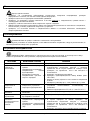
AUX3 / AUX4 auxiliary devices
It is possible to set the functioning of the AUX3 /AUX4 auxiliary devices by setting the dip 6 of SW4 switch:
• dip 6 of SW4 switch set to OFF (default) position: the operator has to press the control key in order to activate the
auxiliary device and then to press it again in order to deactivate it.
• Dip 6 of SW4 switch set to ON position: the auxiliary device remain activated as long as the operator keeps
pressing the relevant control key.
NB: AUX4 can be activated also on alarm contact. For a careful description of this function see the relevant chapter of
alarm contacts.
Connection with the control unit
The J1 connector (see figure of page 7) supplied to the circuit enables the reception and the transmission of digital
data in RS232 or RS485 allowing a rapid connection of several units in case of test runs or for the connection of
conversion interfaces available on the market (RS232-optical fiber...).
For the final connection we recommend using, in case of DCS3 control keyboard use, the RS485 mode with the
relevant connection terminals (maximum distance of 1200 m.) or otherwise, in case of DCS2 control keyboard use, the
Current Loop mode (maximum distance of 1500 m.).

Pag. 11 MNVCDTRX301_1623_EN
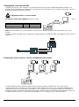
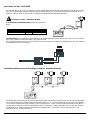
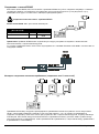
Connection with the RS485 line
The keyboards DCS3, DCJ, DCT and DCTEL and the receiver DTRX3 can be directly connected using the telephone
cable supplied by the manufacturer, using the RJ11 connector (J1 in the figure pag.7) present in the circuit and
referring to the table given below.
Connection keyboard – receiver DTRX3
Communication mode RS485: max. distance 1200
metres
Keyboard (RJ11 A or B)
DTRX3
TX-485A White
-------
Blue RX-485A
TX-485B Yellow
-------
Black RX-485B
Note: The receiver DTRX3 has the load inserted in reception and is connected to line A or B on the keyboard with the
load inserted.
On the receiver side it is also possible to make a simpler connection to terminals RX-485A and RX-485B as in the
following scheme.
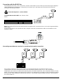
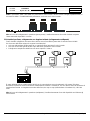
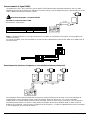
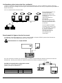
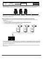
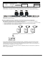
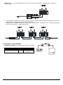
Connecting more than one receiver in cascade (point-to-point connection)
The receivers DTRX3 are able to regenerate the received signal internally and retransmit it along a new
communication line to the subsequent receiver. Each of the three sections of line (L1, L2, L3) is considered
independent, and connects only two devices point-to-point, each with inserted load, over a maximum distance of 1200
metres. The distance between the keyboard and receiver D can therefore be up to 3600 m (1200 m between keyboard
and receiver B, 1200 m between receiver B and receiver C, and a further 1200 m between receiver C and receiver D,
for a total of 3600 m).

Pag. 12 MNVCDTRX301_1623_EN
Keyboard
phone cable
RJ-Jack
DTRX3
RS485A
connectors
white
-----------------------
RX-485A
RS485B
RJ11 ‘A’ or ‘B’
yellow
-----------------------
RX-485B
Note: Terminals RX-485A and RX-485B which have the load inserted, should be connected to terminals TX-485A and
TX-485B respectively of the preceding unit, which also have the load inserted:
NB: For the connection in question (point-to-point) faulty operation of one of the receivers will switch off all the devices
in cascade.
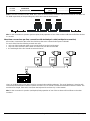
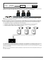
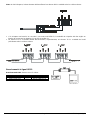
More than one receiver per line, connection with twisted pair cable (multipoint connection)
All receivers connected to the same line should use the same communication protocol RS485.
For each of the lines the following remarks are valid:
• only one of the keyboards (that at one end of the line) has the load inserted
• only one of the receivers (at the other end of the line) has the load inserted
• the total length of the line should not exceed 1200 m
Line A on keyboard DCS3 has been used for communication with the telemetry. The ends (Keyboard - Receiver A3)
should have the termination resistor inserted. Receivers A1, A2 should not have the termination resistor inserted. The
maximum line length, from end to end (from the keyboard to receiver A3), is 1200 metres.
NB: For the connection in question (multi-point) faulty operation of one of the receivers will not influence the other
receivers.

Pag. 13 MNVCDTRX301_1623_EN
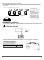
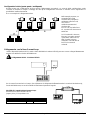
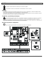
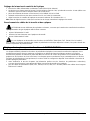
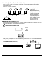
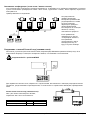
Mixed configurations (point-to-point / multi-point)
This is a combination of the two previous connection modes and, depending on the combination chosen, allows the
user to exploit the advantages of the two types of connection to the utmost, significantly reducing the probability of
faulty operation.
The following is an example of mixed connection:
In the example shown, if
receiver R3 jams (multi-point
connection in line L3) it will
not cause faulty operation in
receiver R4.
R3 is not at the ends of line
L3, and it is not therefore
necessary to terminate it.
If receiver R2 jams, since it
is the ‘generator’ of line L3,
all receivers connected to it
in cascade (R3 and R4) will
not receive the commands.
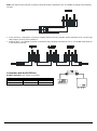
Connection with the Current Loop line
The various devices (keyboard DCS2, video matrix SM328B and receiver DTRX3) can be connected directly using the
telephone cable supplied by the manufacturer:
Connection DCS2 - receiver DTRX3
For normal connections in the field, refer to the connections made using the shunt boxes RJ, supplied by the
manufacturer, following the reference tables given below:
Current Loop Communication Mode:
max. distance 1500 metres from DTRX3.
Jumper JP2 and JP3 on position CL.
DCS2 / DCMT8
DTRX3
TX CL Yellow
-------
Terminal RX CL
GND CL Red
-------
Terminal AGND

Pag. 14 MNVCDTRX301_1623_EN
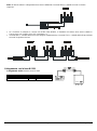
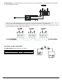
Note: from the Receiver side the connection should be made to terminals RXCL and AGND according to the following
scheme:
• if the receiver is connected in cascade to another DTRX3 unit, the reception mode should be set in Current Loop
with jumpers JP2 and JP3 in position CL.
• terminals RX CL and AGND should be connected to the preceding unit terminals TX CL and AGND respectively as
in the following scheme:
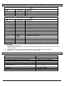
Connection with the RS232 line
RS232 Connection: max. distance 15 metres.
DCS2/DCMT8
DTRX3
TX RS232 Black
--------
Yellow RX RS232
GND RS232 Green
--------
Red GND RS232

Pag. 15 MNVCDTRX301_1623_EN
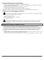
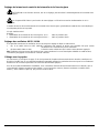
Adjusting the voltage of the optics controls
• connect the power supply cable and power the DTRX3 unit (LD1 lit up)
• insert a load between terminals FOCUS NEAR and FOCUS FAR to absorb at least 10 mA (use a resistor from 100
to 1000 ohm).
• position the tester prods on terminals FOCUS NEAR and FOCUS FAR
• keep one of the two FOCUS keys on the control unit pressed down
• adjust the control voltage of the optics by adjusting trimmer TR1 (default 12V
=)
NB: don’t make unloaded voltage regulation (without inserting the load) otherwise the adjustment will be incorrect.
Connecting the pan&tilt and optics cables
WARNING!: Before carrying out the following operations make sure that the pan&tilt control voltage and the
setting for optics type are correct.
• disconnect the power supply to the unit
• make the connections with the optics and pan&tilt
• reconnect the power supply to the unit
For optics and pan&tilt with PRESET functions (PAN,TILT, ZOOM, FOCUS and IRIS, VCC and GND), the
maximum length of the preset cables should not exceed 5 metres, otherwise positioning on the stored positions will be
incorrect.
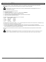
Setting the receiver for PRESET functions
The DTRX3 receiver has integrated preset functions (for pan&tilt and the optics). It is possible to store up to a
maximum of 14 positions using the standard Videotec protocol or up to a maximum of 40 positions using the MACRO
and Pelco D protocols. All positions can be recalled using the keyboard with the Scan and Patrol functions. The
receiver is able to make a test to automatically detect which preset functions are present and configuring the device is
therefore a simple operation. However, it is necessary to take certain precautions:
• Before making the receiver test (to determine which preset functions are active), make sure the cables for pan&tilt
and the optics have been connected correctly
• For the preset cables (PAN, TILT, ZOOM, FOCUS, IRIS, VCC and GND) use cables with a maximum length of 5
metres

Pag. 16 MNVCDTRX301_1623_EN
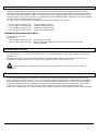
Testing the DTRX3 receiver
After having connected the positioning device and the lens cables, to check the correct working of the devices, it is
necessary to perform the automatic test which will show the allowed functions.
WARNING! Since during this phase the positioning devices makes automatically some predetermined
movements, do not lean on during the test and do not obstruct its trajectory.
Proceed according to the following indications:
1. power the receiver on
2. identify the Up arrow-switch (P4 switch) and the reset switch (P1 switch)
3. keep pushing the Up switch and press the reset switch
4. release the reset switch (keep pushing the Up switch): the automatic test starts
5. after the starting of the test, release the Up switch
The receiver starts up one function at a time, for about 3 seconds:
• Pan: left-right Led P
• Tilt: low-high Led T
• Zoom: wide-tele Led Z
• Focus: far-near Led F
• Iris: close-open Led I
The result of the test is shown from the 5 control leds P, T, Z, F, I (placed near the arrow-switches, see the receiver
scheme at page 7), at the end of the of the movement of the Pan&Tilt and lens:
• led switched on and fixed: the relevant function (pan P, tilt T, zoom Z, focus F, iris I) works correctly.
• Led switched on and blinking: the relevant function doesn’t work or is not present and cannot be used for
preset/scan/patrol functions.
After some seconds from the end of the test the receiver automatically starts working.
Warning! A blinking of at least one of the leds at the end of the test (provided that this function is included)
indicates a malfunction to which you must find a remedy before the receiver starts working.
La pagina si sta caricando...
La pagina si sta caricando...
La pagina si sta caricando...
La pagina si sta caricando...
La pagina si sta caricando...
La pagina si sta caricando...
La pagina si sta caricando...
La pagina si sta caricando...
La pagina si sta caricando...
La pagina si sta caricando...
La pagina si sta caricando...
La pagina si sta caricando...
La pagina si sta caricando...
La pagina si sta caricando...
La pagina si sta caricando...
La pagina si sta caricando...
La pagina si sta caricando...
La pagina si sta caricando...
La pagina si sta caricando...
La pagina si sta caricando...
La pagina si sta caricando...
La pagina si sta caricando...
La pagina si sta caricando...
La pagina si sta caricando...
La pagina si sta caricando...
La pagina si sta caricando...
La pagina si sta caricando...
La pagina si sta caricando...
La pagina si sta caricando...
La pagina si sta caricando...
La pagina si sta caricando...
La pagina si sta caricando...
La pagina si sta caricando...
La pagina si sta caricando...
La pagina si sta caricando...
La pagina si sta caricando...
La pagina si sta caricando...
La pagina si sta caricando...
La pagina si sta caricando...
La pagina si sta caricando...
La pagina si sta caricando...
La pagina si sta caricando...
La pagina si sta caricando...
La pagina si sta caricando...
La pagina si sta caricando...
La pagina si sta caricando...
La pagina si sta caricando...
La pagina si sta caricando...
La pagina si sta caricando...
La pagina si sta caricando...
La pagina si sta caricando...
La pagina si sta caricando...
La pagina si sta caricando...
La pagina si sta caricando...
La pagina si sta caricando...
La pagina si sta caricando...
La pagina si sta caricando...
La pagina si sta caricando...
La pagina si sta caricando...
La pagina si sta caricando...
La pagina si sta caricando...
La pagina si sta caricando...
La pagina si sta caricando...
La pagina si sta caricando...
La pagina si sta caricando...
La pagina si sta caricando...
La pagina si sta caricando...
La pagina si sta caricando...
La pagina si sta caricando...
La pagina si sta caricando...
La pagina si sta caricando...
La pagina si sta caricando...
La pagina si sta caricando...
La pagina si sta caricando...
La pagina si sta caricando...
La pagina si sta caricando...
La pagina si sta caricando...
La pagina si sta caricando...
La pagina si sta caricando...
La pagina si sta caricando...
La pagina si sta caricando...
La pagina si sta caricando...
La pagina si sta caricando...
La pagina si sta caricando...
La pagina si sta caricando...
La pagina si sta caricando...
La pagina si sta caricando...
La pagina si sta caricando...
La pagina si sta caricando...
La pagina si sta caricando...
La pagina si sta caricando...
La pagina si sta caricando...
La pagina si sta caricando...
La pagina si sta caricando...
La pagina si sta caricando...
La pagina si sta caricando...
La pagina si sta caricando...
La pagina si sta caricando...
La pagina si sta caricando...
La pagina si sta caricando...
La pagina si sta caricando...
La pagina si sta caricando...
La pagina si sta caricando...
La pagina si sta caricando...
-
 1
1
-
 2
2
-
 3
3
-
 4
4
-
 5
5
-
 6
6
-
 7
7
-
 8
8
-
 9
9
-
 10
10
-
 11
11
-
 12
12
-
 13
13
-
 14
14
-
 15
15
-
 16
16
-
 17
17
-
 18
18
-
 19
19
-
 20
20
-
 21
21
-
 22
22
-
 23
23
-
 24
24
-
 25
25
-
 26
26
-
 27
27
-
 28
28
-
 29
29
-
 30
30
-
 31
31
-
 32
32
-
 33
33
-
 34
34
-
 35
35
-
 36
36
-
 37
37
-
 38
38
-
 39
39
-
 40
40
-
 41
41
-
 42
42
-
 43
43
-
 44
44
-
 45
45
-
 46
46
-
 47
47
-
 48
48
-
 49
49
-
 50
50
-
 51
51
-
 52
52
-
 53
53
-
 54
54
-
 55
55
-
 56
56
-
 57
57
-
 58
58
-
 59
59
-
 60
60
-
 61
61
-
 62
62
-
 63
63
-
 64
64
-
 65
65
-
 66
66
-
 67
67
-
 68
68
-
 69
69
-
 70
70
-
 71
71
-
 72
72
-
 73
73
-
 74
74
-
 75
75
-
 76
76
-
 77
77
-
 78
78
-
 79
79
-
 80
80
-
 81
81
-
 82
82
-
 83
83
-
 84
84
-
 85
85
-
 86
86
-
 87
87
-
 88
88
-
 89
89
-
 90
90
-
 91
91
-
 92
92
-
 93
93
-
 94
94
-
 95
95
-
 96
96
-
 97
97
-
 98
98
-
 99
99
-
 100
100
-
 101
101
-
 102
102
-
 103
103
-
 104
104
-
 105
105
-
 106
106
-
 107
107
-
 108
108
-
 109
109
-
 110
110
-
 111
111
-
 112
112
-
 113
113
-
 114
114
-
 115
115
-
 116
116
-
 117
117
-
 118
118
-
 119
119
-
 120
120
-
 121
121
-
 122
122
-
 123
123
-
 124
124


in altre lingue
- English: Videotec DTRX3 User manual
- français: Videotec DTRX3 Manuel utilisateur
- Deutsch: Videotec DTRX3 Benutzerhandbuch
Documenti correlati
-
Videotec DCRE485 Manuale utente
-
-
-
-
-
-
-
-
-
Altri documenti
-
CAME 62822600 Guida d'installazione
-
-
-
-
Velleman MK161 Manuale utente
-
 Elkron RS232/485 Guida d'installazione
-
-
-
ADTRAN D4 U-BR1 Job Aid
