Hangar 9 HAN3185 Manuale del proprietario
- Categoria
- Giocattoli telecomandati
- Tipo
- Manuale del proprietario

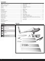
ASH 31 6.4M
Instruction Manual
Bedienungsanleitung
Manuel d’utilisation
Manuale di Istruzioni

2EN
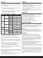
NOTICE
All instructions, warranties and other collateral documents are subject to change at the sole discretion of Horizon
Hobby, LLC. For up-to-date product literature, visit horizonhobby.com and click on the support tab for this product.
Age Recommendation: Not For Children Under 14 Years. This Is Not A Toy.
SAFETY WARNINGS AND PRECAUTIONS
Read and follow all instructions and safety precautions before use. Improper use can result in fire, serious injury and
damage to property.
Components
Use only with compatible components. Should any compatibility questions exist, please refer to the product
instructions, component instructions or contact the appropriate Horizon Hobby office.
Flight
Fly only in open areas to ensure safety. It is recommended flying be done at radio control flying fields. Consult local
ordinances before choosing a flying location.
Propeller
If using the motor powered option, always keep loose items that can become entangled in the propeller away from the
prop. This includes loose clothing or other objects such as pencils and screwdrivers. Keep your hands away from the
propeller as injury can occur.
Batteries
Always follow the manufacturer’s instructions when using and disposing of any batteries. Mishandling of Li-Po
batteries can result in fire causing serious injury and damage.
Small Parts
This kit includes small parts and should not be left unattended near children as choking and serious injury could result.
MEANING OF SPECIAL LANGUAGE
The following terms are used throughout the product literature to indicate various levels of potential harm when
operating this product:
WARNING: Procedures, which if not properly followed, create the probability of property damage, collateral damage,
and serious injury OR create a high probability of superficial injury.
CAUTION: Procedures, which if not properly followed, create the probability of physical property damage AND a
possibility of serious injury.
NOTICE: Procedures, which if not properly followed, create a possibility of physical property damage AND a little or
no possibility of injury.
WARNING: Read the ENTIRE instruction manual to become familiar with the features of the product before
operating. Failure to operate the product correctly can result in damage to the product, personal property and
cause serious injury.
This is a sophisticated hobby product. It must be operated with caution and common sense and requires some basic
mechanical ability. Failure to operate this Product in a safe and responsible manner could result in injury or damage
to the product or other property. This product is not intended for use by children without direct adult supervision. Do
not attempt disassembly, use with incompatible components or augment product in any way without the approval of
Horizon Hobby, LLC. This manual contains instructions for safety, operation and maintenance. It is essential to read and
follow all the instructions and warnings in the manual, prior to assembly, setup or use, in order to operate correctly and
avoid damage or serious injury.
SAFE OPERATING RECOMMENDATIONS
• Inspect your model before every flight to ensure it is airworthy.
• Be aware of any other radio frequency user who may present an interference problem.
• Always be courteous and respectful of other users in your selected flight area.
• Choose an area clear of obstacles and large enough to safely accomodate your flying activity.
• Make sure this area is clear of friends and spectators prior to launching your aircraft.
• Be aware of other activities in the vicinity of your flight path that could cause potential conflict.
• Carefully plan your flight path prior to launch.
• Abide by any and all established AMA National Model Aircraft Safety Code.
BEFORE STARTING ASSEMBLY
• Remove parts from bag.
• Inspect fuselage, wing panels, rudder and stabilizer for damage.
• If you find damaged or missing parts, contact your place of purchase.
• Charge transmitter and receiver batteries.
• Center trims and sticks on your transmitter.
• For a computer radio, create a model memory for this particular model.
• Bind your transmitter and receiver, using your radio system’s instructions.
NOTICE: Rebind the radio system once all control throws are set. This will keep the servos from moving to their
endpoints until the transmitter and receiver connect. It will also guarantee the servo reversal settings are saved in
the radio system.
FAA INFORMATION
If you own this product, you may be required to register with the FAA.
For up-to-date information on how to register with the FAA, please visit https://registermyuas.faa.gov/.
For additional assistance on regulations and guidance on UAS usage, visit knowbeforeyoufly.org/.

3EN
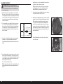
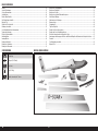
ASH 31 6.4M ARF
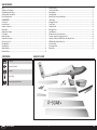
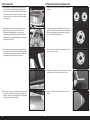
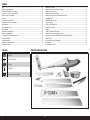
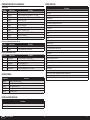
SPECIFICATIONS LARGE PARTS LAYOUT
252 in (6.4m)
1920 sq in (123.87 dm2)
88 in (2.2m)
26 lbs (11.8 kg)
6-channel (or greater) with 7 servos
Notice ...................................................................................................................................................................... 2
Meaning of Special Language ..................................................................................................................................2
Safety Warnings and Precautions .............................................................................................................................2
Safe Operating Recommendations ...........................................................................................................................2
Before Starting Assembly ......................................................................................................................................... 2
FAA INFORMATION ...................................................................................................................................................2
Specifications ..........................................................................................................................................................3
Large Parts Layout ................................................................................................................................................... 3
Required for Completion ..........................................................................................................................................4
Optional Parts ..........................................................................................................................................................4
Additional Items Required ........................................................................................................................................4
Tools Required .........................................................................................................................................................4
Building Precautions ................................................................................................................................................5
Transportation and Storage ...................................................................................................................................... 5
Fluorescent Color Care .............................................................................................................................................5
Outer Wing Panels ...................................................................................................................................................5
Inner Wing Panels ....................................................................................................................................................7
Winglet Installation ................................................................................................................................................10
Rudder Installation ................................................................................................................................................. 10
Elevator Installation ...............................................................................................................................................12
Tow Release Installation.........................................................................................................................................13
Radio Installation ...................................................................................................................................................13
Cockpit Installation ................................................................................................................................................14
Optional Electric Power System Installation ............................................................................................................ 14
Final Assembly ....................................................................................................................................................... 17
Balancing the Aircraft.............................................................................................................................................18
Control Throws ......................................................................................................................................................19
Preflight Checklist .................................................................................................................................................. 19
Daily Flight Checks ................................................................................................................................................19
Limited Warranty ...................................................................................................................................................19
Warranty and Service Contact Information .............................................................................................................20
Compliance Information for the European Union .....................................................................................................20
Instructions for Disposal of WEEE by Users in the European Union .......................................................................... 20
AMA National Model Aircraft Safety Code ..............................................................................................................21
Replacement Parts ................................................................................................................................................. 22
Recommended Parts .............................................................................................................................................. 22
Optional Parts ........................................................................................................................................................22
TABLE OF CONTENTS

4EN
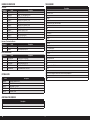
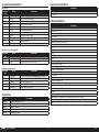
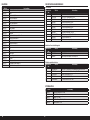
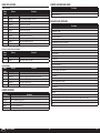
REQUIRED FOR COMPLETION
ADDITIONAL ITEMS REQUIRED
TOOLS REQUIRED
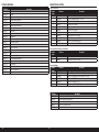
# Required Part # Description
1 SPMAR12310T AR12310T 12CH PowerSafe Tele RX
4 SPMSA5060 A5060 H-T / H-S Mini Metal HV Servo
2 SPMSA7050 A7050 HV Thin Wing Hi Torq MG
3 SPMA3003 Heavy-Duty Servo Extension 12-inch
8 SPMA3004 Heavy-Duty Servo Extension 18-inch
5 SPMA3005 Heavy-Duty Servo Extension 24-inch
4 SPMA3007 Heavy-Duty Servo Extension 48-inch
1 SPMA3008 Heavy-Duty Y-Harness 6-inch
2 SPMB4000LPRX 4000mAh 2S 7.4V LiPo Rx Battery
1 SPMA3054 Servo Connector Clips (25)
1 SPMVR5203 VR5203 Dual Output Regulator
Description
6+ channel transmitter
LiPo battery charger
All Versions
Unpowered, Tow-Launched Version
Electric Powered Version
# Required Part # Description
1 SPMSA7040 A7040 HV Retract Servo
DLMBD38 Liquid Gravity; Weight System
# Required Part # Description
1 CSE010009700 Talon 90 Heli ESC 010-0097-00
1 EFLM4060B Power 60 BLOutrunner Mtr, 470Kv
1 EFLP16080FA Spinner, 45mm: ASW 20 4.7m
1 HAN495512 Propeller 16 x 10: ASW 20 4.7m
1 KXSB40006S40 F-Tek 4000mAh 6S 40C, EC5, LED
Description
Balancing stand
Box wrench: 17mm
Clamps
Clear tape
Crimping tool
Cyanoacrylate (CA) glue, thin and medium
Drill with various size bits
Epoxy
Epoxy brushes
Felt-tipped pen
Isopropyl alcohol
Hemostat
Hex drivers, metric, various sizes
Hobby knife
Long plastic pushrod
Low-tack masking tape
Medium grit sandpaper
Metric ruler
Microballoons
Mixing cups and sticks
Paper towels
Pencil
Phillips screwdriver: #1, #2
Pin vise
Pliers
Rotary tool with cutting disk, drum sander, carbide cutter, grinding stone
Soldering iron and solder
String
Part # Description
SPMA3008 Heavy-Duty Y-Harness 6 inch
SPMAS3000 AS3000 AS3X Stabilization Module
TAM85013 Spray Lacquer TS-13 Clear
TAM86024 PS-24 Fluor Org 100ml Spray Can
TAM87044 Primer White 180ml
OPTIONAL PARTS

5EN
ASH 31 6.4M ARF
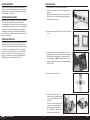
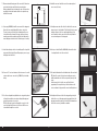
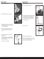
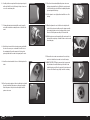
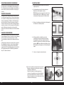
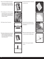
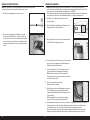
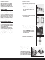
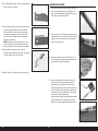
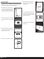
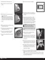
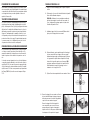
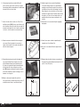
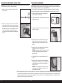
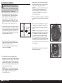
1. Remove packing tape, clean and polish the wing surface.
3. Find the short servo mounts. Drill pilot holes for the servo mounting
screws.
4. Carefully roughen the wing servo mounting surface for the servo
mount using either a rotary tool on low speed or 80 grit sandpaper.
Only lightly scuff the inner surface of the wing panel to give the
epoxy something to grip. DO NOT sand through the surface of the
wing panel. Clean the mounting surface thoroughly with denatured
alcohol or 91% IPA.
5. Cut 3 arms from a 4 arm servo horn.
6. Test fit the servo with the servo arm
installed. Enlarge the opening in the mount
as necessary to allow the servo to sit fully
in the mount.
Test fit the servo mount screws as well to
ensure they do not protrude through the
mount and damage the wing surface. If
the screws protrude, cut them off so they
are below the surface of the mount.
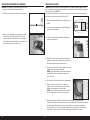
BUILDING PRECAUTIONS
Prepare the work surface prior to beginning the build. The surface
should be soft and free of any sharp objects. We recommend resting
the airframe parts on a soft towel or pit mat to prevent scratching or
denting the surface of the aircraft.
TRANSPORTATION AND STORAGE
When transporting and storing your model, you will need a minimum
of 80 inches (2m) in length, and 18 inches (46cm) in height to
accommodate the size of the fuselage. We also recommend the use of
wing and stabilizer bags to help protect these surfaces during transport
and storage. The control horns and linkages can cause damage to
other surfaces even when placed in storage bags. Always transport
and store the wings and stabilizer so the linkages do not contact other
panels to prevent damage.
FLUORESCENT COLOR CARE
The fluorescent color used on your model can fade with exposure to
direct sunlight over time. To increase the longevity of the fluorescent
color on the aircraft, limit the exposure to direct sunlight when not flying.
If repairs become necessary or if you decide to color optional parts
to match the fuselage color, Tamiya spray color, PS-24, Fluorescent
Orange is a close match to the color used on the model. For best
results, PS-24 needs to be sprayed over Tamiya Fine White Primer
(TAM87044) and clearcoated with Tamiya TS-13, Clear.
OUTER WING PANELS
2. Cut an access hole in the root end of the outer wing panel using a
rotary tool.
TIP: Make the hole just large enough for the servo connector to fit
through. If the hole is too big, the extension will fall back into the
wing panel when disconnected.

6EN
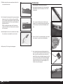
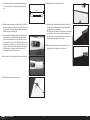
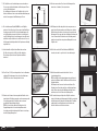
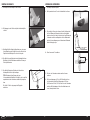
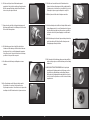
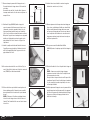
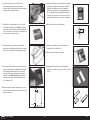
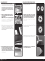
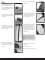
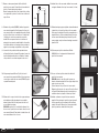
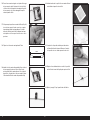
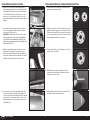
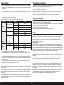
Measure and mark the wing panel at the servo hatch;
10mm from raised outer hatch edge and 45mm from rear raised edge.
7. Measure and mark the wing panel at the servo hatch; 10mm from
raised outer hatch edge and 45mm from rear raised edge.
When mounting the frame in the wing, the edge of the frame lines
up with the front and back marks, and the servo output lines up
with the 45mm mark.
8. Using epoxy (DLMAD64), install the servo mount to the wing panel.
Ensure the servo arm will align with the surface control horn.
The arm clearance notch should face the wingtip and the servo
lead notch should face forward. Clean any epoxy from the servo
mounting area, which may interfere with the servo fitting into the
mount, with paper towel and alcohol. Allow the epoxy to cure fully.
9. Install anti-rotation pins in the root end with epoxy. Do not push the
pin in past half the length of the pin. Wipe away any excess epoxy
with paper towel and alcohol.
10. Connect a 12” servo lead extension to the aileron servo. Secure the
extension with a servo connector clip (SPMA3054) or heat shrink
tubing.
11. Use either a string with a weight attached or a long plastic pushrod
to thread the assembled servo extension through the wing panel
and out the previously cut access hole.
TIP: Feed the string or plastic rod through the access hole to the
servo hatch and attach the servo lead to the end. Pull the servo
lead end back through the access hole.
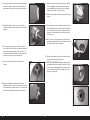
12. Install the servo arm. Install the servo in the mount using short
servo screws (2 x 8mm).
13. Carefully measure and cut the hole in the hatch for the servo arm
using a rotary tool or hobby knife. Test fit the hatch often to ensure
adequate clearance of the servo arm through full travel of the
servo. Round the outside corners of the hatch to fully fit into the
recessed mounting area of the wing panel.
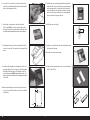
14. Cut a piece of white UltraTrim (HANU80000) adhesive film about
3cm larger than the size of the servo hatch.
15. Peel and stick the adhesive film to the finished side of the servo hatch.
TIP: Start at the center of the hatch and carefully press any air
bubbles and wrinkles out of the film as you work your way to the
edges.
Cut and remove the hole for the servo arm. Trim the film to
approximately 10mm past the edge of the hatch and ease the
corners as shown to help prevent the corners from lifting after use.
16. Carefully install the servo hatch to the wing panel by placing the
hatch in the recess of the wing panel and pressing the film to the
wing panel around the perimeter of the hatch. Work outward from
the hatch to remove any air bubbles or wrinkles.
10mm
45mm

7EN
ASH 31 6.4M ARF
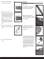
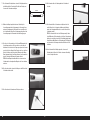
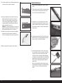
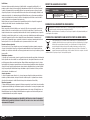
17. With the aileron held at center, measure between the holes of the
servo arm and the control horn.
18. Set the length of the aileron pushrod to the measurement above by
turning in or out on the clevis at either end of the pushrod. When
the correct length is achieved, apply thread locking compound and
tighten the nuts against the clevis. Try to center the threaded rod
between the two clevises.
TIP: The excess threaded rod may be cut off, if desired. Leave
enough of the rod that at least 3 threads are visible on the inside of
the clevis, as shown.
19. Install the pushrod to the servo and control surface horns. Ensure
the control surface is centered when the servo is at neutral.
20. Repeat steps 1–19 for the opposite outer wing panel.
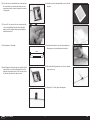
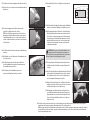
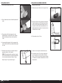
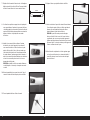
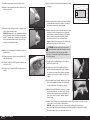
2. Lay the finished outer wing panel next to the inner wing panel as
shown. Mark the location of the outer wing access hole on the
inner wing panel.
4. Connect a 48” and 24” servo extension together to create an inner
aileron extension. Secure with a clip or heat shrink tubing.
3. Cut access holes in both the outer and root ends of the inner
wing panel. The holes should be just large enough to fit the servo
connectors through to keep the ends from falling back into the
wing.
5. Insert a long plastic pushrod or weighted string through the cut
access hole in either end of the panel and out the flap servo hatch.
Attach one end of the assembled aileron servo extension to the
pushrod. Pull the extension end through the wing panel and out the
access hole. Tape the extension end to the end of the wing panel.
Repeat the procedure from the other end of the panel to pull the
opposite end of the aileron servo extension through the access
hole in the other end of the wing panel.
INNER WING PANELS
1. Remove packing tape, clean and polish the wing surface.

8EN
10mm
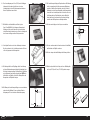
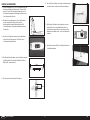
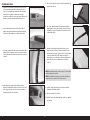
6. Connect an 18” servo extension to the spoiler lead and secure it
with a clip or heat shrink tubing. Thread the extension through the
inner end of the wing panel as before.
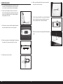
11. Install the flap servo mount using epoxy. Align the mount with the
marks made in the previous step. Remove any epoxy that squeezes
into the mounting lug slots or the inner base of the mount which
may interfere with the servo. Ensure the mount bonds to the wing
spar as well as the surface and that the servo arm will align with
the flap control horn. Allow epoxy to fully cure.
8. Carefully trim the webs from the servo mounting lugs. Test fit the
servo in the servo mount. The servo should be a very snug fit in the
mount.
13. Center the servo and install the control horn angled slightly toward
the trailing edge of the wing.
14. Slide the servo into the mount as shown.
7. Using hot glue or contact adhesive, such as Deluxe Systems
Foam2Foam (DLMAD34), secure the aileron and spoiler leads to
the spar at the front of the servo hatch. Doing so will keep the leads
from shifting and interfering with the flap servo arm and pushrod.
12. Cut the flap servo arm to length.
9. Carefully scuff the wing flap servo mounting surface for the servo
mount using either a rotary tool on low speed or 80 grit sandpaper.
Only lightly scuff the inner surface of the wing panel to give the
epoxy something to grip. DO NOT sand through the surface of the
wing panel. Clean the mounting surface thoroughly with denatured
alcohol or IPA.
15. Using the acetate template provided, create a servo retention plate
using 1/8” and 1/16” ply.
10. Measure and mark the flap servo hatch opening, 12mm from the
rear recess line and 17mm from the outer recess line, as shown in
the illustration.
17mm
12mm

9EN
ASH 31 6.4M ARF
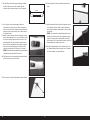
79mm
16. Secure the servo in the mount with the servo retention plate and
two screws. Ensure the screw heads sit below the servo hatch
mounting surface and the screws don’t damage the outer surface
of the wing panel.
17. Connect a 24” servo extension to the servo lead and secure with
a clip or heat shrink tubing. Thread the extension through the
wing root end of the wing panel, using a long plastic pushrod or
weighted string as before.
18. Cut the pushrods to 79mm length.
19. Install the pushrod to the flap horn and servo arm. Deflect the flap
down and insert one end of the pushrod through the hole in the
trailing edge of the wing and connect it to the servo arm. Connect
the other end of the pushrod to the flap control horn.
20. Install the servo hatch to the wing with tape as done on the outer
wing panel.
21. Install anti-rotation pins in the root end of the panel with epoxy.
Wipe away any excess epoxy with paper towel and alcohol.
22. Trim and attach the flap pushrod exit cover to the top of the wing
using contact cement.
23. Repeat steps 1–22 for the opposite inner wing panel.

10EN
13mm
1. Clean and polish the fuselage.
2. Remove the tailwheel using a 2.5mm hex driver.
3. Feed a weighted string or long flexible pushrod through the elevator
servo opening, through the vertical fin, through the small hole in
front of the rudder servo opening and up through the fuselage
tail. This will be used later to pull the rudder and elevator servo
extensions through the fuselage.
4. Trim a servo arm to 13mm.
5. Center the rudder servo and install the servo arm.
6. A 60” servo extension is required for the rudder servo. Connect a
48” and a 12” extension to the rudder servo. Secure all connections
with servo extension clips or heat shrink tubing.
RUDDER INSTALLATION
1. Slide the winglet blade into the winglet slot.
2. Slide the assembly into the slot in the outer wing panel tip.
3. Trim the winglet blade to length, if necessary, to achieve a tight fit
of the winglet against the wing panel. There should not be a gap
between the panel and the winglet.
4. The blade should be a tight fit in both the winglet and the outer
wing panel. The winglet should be taped in place for added
security.
WINGLET INSTALLATION
5. Using epoxy, attach a wing tip wheel to the outer wing panel
bottom, near the tip.
TIP: Use fine grit sandpaper or a scouring pad to very lightly scuff
the surface of the wing panel where the wheel will be attached to
give the epoxy something to grip.
Repeat steps 1-5 for the opposite wingtip.

11 EN
ASH 31 6.4M ARF
12. Push the rudder over the hinge points in the fin.
13. Carefully insert the rudder hinge pin through the hole in the top of
the rudder and feed it fully through each of the hinge points until it
exits through the bottom of the rudder.
TIP: The hinge pin is a tight friction fit. It may be necessary to lightly
push or pull on the rudder as the pin is inserted to get the pin to
seat fully. Do not force the pin through. If you feel resistance, move
the rudder slightly and continue to insert the pin.
14. When fully inserted, the hinge pin may be taped at the top of the
rudder if desired or if the hinge pin is excessively loose.
95mm
7. Trim the rudder pushrod so the finished length is 95mm between
the clevis pins. Attach one end of the pushrod to the rudder servo
arm.
8. With the fuselage upside down in a stand, feed the servo extension
through the rudder servo cutout and out the elevator servo cutout at
the top of the fin. This extension will be pulled through the fuselage
with the elevator servo extension later.
9. Install the rudder servo through the tailwheel opening and into the
servo mount. The servo is installed with the output shaft toward
the front of the aircraft and the servo arm toward the left side of
the fuselage. Feed the open end of the pushrod through the molded
opening in the tail as you fit the servo into place. Keep some tension
on the servo lead to ensure the lead is not pinched in the opening.
TIP: Use a magnetic screwdriver or attach a small magnet to a
regular screwdriver to install the servo screws.
10. Rotate the servo horn so the pushrod extends out the back of the fin.
11. Attach the rudder control horn to the pushrod.

12EN
53mm
10mm
1. A 72” servo extension is required for the elevator servo. Connect
a 48” and a 24” extension together and connect to the elevator
servo. Secure all connections with clips or heat shrink tubing.
2. Tape the ends of the rudder and elevator servo extensions to
the end of the flexible pushrod or string that was inserted in the
fuselage earlier. Carefully pull the servo extensions through the
fuselage and up to the cockpit.
3. Fit the elevator servo into place with the output shaft toward the
front of the aircraft. Ensure the servo lead is not pinched.
4. Trim the elevator pushrod so the finished length is 53mm between
the clevis pins. The clevises should be at 90° to each other.
5. Trim the elevator servo arm to 10mm.
6. Attach one end of the pushrod to the elevator servo arm and the
other end to the elevator control horn.
7. Feed the elevator pushrod with the servo arm attached through the
top of the fin. Center the elevator servo. Attach the servo horn to
the servo output shaft at 90° as shown in the illustration.
8. Attach the horizontal stab to the fin using two M4 X 20mm flathead
screws.
ELEVATOR INSTALLATION

13 EN
ASH 31 6.4M ARF
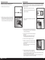
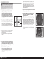
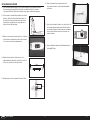
2. Install the tow release servo into the nose of the fuselage. Slide
the release wire through the small hole in the front of the cockpit.
Attach the arm to the servo, ensuring the wire fully opens at one end
of the servo travel and fully closes at the opposite end of travel.
IMPORTANT: While the spoilers and retract will operate on 7.2V, for increased longevity and reliability, we recommend
regulating the power input of these components to 5.2V with the use of an inline voltage regulator, such as SPMVR5203.
If the retract is slow to operate or does not retract to the fully locked position at the regulated voltage, run the retract
directly to the receiver at 7.2V.
IMPORTANT: If you are installing the electric power option, skip this
section and see the optional electric power installation secton.
1. Carefully cut the rear of the cockpit floor in the area shown.
2. Connect the gear and spoiler channels from the receiver to the
input ports of the regulator.
3. Connect the output ports of the regulator to the gear lead and the
spoiler y-harness.
4. Route all servo leads from the tail to the forward fuselage, keeping
them as organized as possible. Use wire ties or hook and loop tape
to secure the leads in the fuselage.
5. Prepare six 18-inch servo leads; two for ailerons, two for flaps and
two for spoilers.
TIP: Use different colored tape wrapped around the ends of the
leads to differentiate which leads go to which control surface.
6. Connect all servo leads to the appropriate receiver ports.
7. Mount the receiver under the rear of the cockpit floor as shown. If
necessary, use small pieces of foam or hook and loop tape to hold
the receiver in place.
TIP: If desired, cut holes in the rear of the cockpit floor and route
the servo leads to the receiver.
8. Temporarily mount the receiver batteries as far forward in the
cockpit as possible. The battery location will be finalized after the
correct center of gravity has been established. The unpowered, glider version will have the batteries mounted as
far forward as possible, along with additional nose weight.
The electric powered version does not require additional nose weight to balance, and depending on the motor
battery used, may require the receiver batteries to be moved rearward.
1. Install the tow release wire to the servo arm.
TOW RELEASE INSTALLATION RADIO INSTALLATION

14EN
COCKPIT INSTALLATION
1. Install the fiberglass cockpit tub. Squeeze gently on the sides of
the tub to fit it between and under the molded fuselage sides.
The holes in the tub should line up with the holes in the fuselage.
It is not necessary to secure the tub to the fuselage. The tub is
removable to allow for access to the rear of the fuselage and the
lower cockpit area.
2. Install an optional pilot into the tub for added scale realism if
desired. It is not necessary to secure the pilot to the tub.
TIP: Hangar 9 has partnered with two companies who offer
custom pilots; www.warbirdpilots.com in the United States and
www.tailoredpilots.com in the United Kingdom offer very detailed
pilot figures to suit the ASH 31.
3. Install the canopy to the fuselage by inserting the pin at the front
of the canopy into the hole at the front of the fuselage and rotating
the back of the canopy down against the fuselage, ensuring the
side alignment lugs insert into the holes in the fuselage.
4. Slide the wire canopy lock, located under the left wing root, in until
the canopy is secured. It may be necessary to press gently on the
back of the canopy to get it to latch fully. The wire lock is purposely
a tight fit to prevent coming loose in flight.
OPTIONAL ELECTRIC POWER SYSTEM INSTALLATION
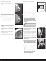
1. Roughen one side of each of the motor mount pieces using 80 grit
sandpaper.
2. Using 5-minute epoxy, glue the roughened sides of the two motor
mount pieces together, ensuring the holes line up accurately. Clean
up any excess epoxy with alcohol and a paper towel. Clamp the
pieces together until the epoxy fully cures.
3. Trace a line around one side of the mount approximately 1.5mm
from the outer edge, as shown.
4. Using the line as a guide, sand a bevel on the edge of the mount by
sanding across the edge, from the back corner to the line.
5. Using 1/8” tape, mark a line 25mm back from the nose of the
fuselage.

15 EN
ASH 31 6.4M ARF
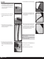
6. Carefully cut the nose away from the fuselage using a rotary tool
with a cutoff disk. Do not cut all the way to the tape. Leave some
excess to be sanded away later.
7. Following the instructions included with the motor, change the
motor shaft orientation for mounting the motor to the back of the
mount.
8. Attach the motor mount to the motor using screws provided with
the motor. If necessary, use a countersink to bevel the holes in
the mounting plate. Ensure the narrow side of the edge bevel
previously sanded into the mount is facing away from the motor.
9. Insert the motor and mount into the nose of the fuselage from the
inside.
10. Press the propeller adapter onto the motor shaft and loosely install
the propeller nut. Install the spinner over the propeller adapter.
Ensure the spinner is fully seated over the adapter. Install the
spinner center screw.
11. Press the motor forward and tighten the spinner center screw
while pressing against the motor. Tighten the screw just enough
to hold the motor in place but still allow for adjusting the spinner
placement against the fuselage.
12. Use the spinner to correctly align the motor with the nose of the
fuselage.
13. When the alignment is correct, hold the motor steady from the
inside of the fuselage and carefully remove the spinner assembly
by loosening the spinner center screw, being careful to not move
the motor. Slide the spinner assembly off of the motor shaft.
14. With the spinner removed, temporarily tack the motor mount to the
fuselage with a couple drops of medium CA and accelerator around
the mounting ring.
15. Remove the motor mount screws and remove the motor, being
careful not to break the motor mount loose from the fuselage.
16. DO NOT SKIP THIS STEP. Apply a generous bead of epoxy around
the joint between the mount and fuselage, both in front of and
behind the motor mount. Press the epoxy into the joint and smooth
it to form a fillet. Allow the epoxy to fully cure before continuing.

16EN
17. Temporarily install the motor and spinner assembly.
18. Measure and mark 1mm back from the spinner around the
fuselage.
19. Remove the spinner assembly and motor and sand the front of the
fuselage back to the line.
TIP: Use a sanding block to keep the front of the fuselage straight.
Remove material slowly and check the progress often. The goal is
to get a perfectly straight line that is parallel with the back of the
spinner around the circumference of the fuselage.
20. Mount the motor to the motor mount using medium thread locking
compound.
21. Use hook and loop tape or servo tape to install the ESC in the
cockpit.
22. Connect the motor leads to the ESC following the instructions
included with the motor and ESC.
23. Connect the ESC throttle lead to the appropriate reciever port.
24. Cut and remove the section of the cockpit floor shown.
25. Mount the motor battery in the cockpit floor and secure using hook
and loop straps through the pre-cut holes in the cockpit floor.
26. Mount the receiver batteries at the rear of the cockpit. The receiver
batteries can be moved accordingly to adjust the balance of the
aircraft. When using the recommended optional power system
components no additional ballast should be required. However,
proceed to the Balancing the Aircraft section to confirm the correct
center of gravity.
CAUTION: Never attempt to fly without properly balancing the
aircraft. An un-balanced aircraft will be extremely unstable and
may cause a crash. Crash damage is not covered under warranty.
27. Prepare the spinner yoke by installing the tapered shaft and nut.
Do not tighten the nut at this time.
28. Check the fit of the propeller blades to the yoke. The blade should
move freely when the pin is installed. If not, lightly sand the blades
where they contact the yoke to allow free movement.
29. Once the blades fit the yoke, use the pins and clips to secure the
blades to the yoke. Ensure the front of the blades are facing toward
the notched side of the yoke.
30. Fit the assembly to the motor shaft. Check that the yoke can rotate
freely and not contact the front of the fuselage through its full
rotation. Use a 12mm wrench to tighten the nut, securing the yoke
and adapter.
31. Install the spinner, making sure it fits into the notches in the
propeller yoke. Use the screw provided with the spinner and a
#1Phillips screwdriver to secure the spinner to the adapter.
TIP: The spinner and propeller blades may be painted to match
the fluorescent orange of the aircraft nose, using the products
mentioned in the Fluorescent Color Care section, making the
spinner and propeller almost invisible during flight.

17 EN
ASH 31 6.4M ARF
1. Cut a hole in the wing root of the fuselage for the various servo leads
from the wing. Ensure the hole aligns with the hole previously cut in
the root of the inner wing panel and it is large enough to allow the
servo lead connectors to pass through. Use sandpaper to remove
any sharp edges around the hole.
2. Insert the wing joiner into the fuselage. The joiner should be a snug
fit in the fuselage opening. Ensure the joiner is centered in the
fuselage.
3. Slide the inner wing panels over the ends of the wing joiner,
connecting the servo leads and inserting the wing alignment pin in
the fuselage as you slide the panel on.
4. Thread the wing retention nut onto the threaded wing stud from
the inside of the fuselage. Hand tighten the retention nut, ensuring
the various servo leads are not pinched between the wing and the
fuselage.
5. Slide an outer wing tube into the outer end of the inner wing panel.
FINAL ASSEMBLY
NOTICE: Always ensure the wing is clean, dry and free from any dust or
debris prior to installing the tape.
NOTICE: Do not re-use the tape after disassembling the wing. Use new
tape every time the wing is reassembled.
6. Slide the outer wing panels over the wingtube until the outer panel
contacts the inner panel. Ensure the wing alignment pin is inserted
into the wing alignment hole.
7. Wrap the seam between the inner and outer panel with tape. Ensure
the tape does not interfere with the operation of the wing control
surfaces. White PVC electrical tape is recommended. We have found
this tape to be more than sufficient to retain the outer wing panels in
flight, even during aggressive aerobatic maneuvers.
8. Install the tip winglet as described in the Winglet Installation section.
9. Repeat steps 1-8 for the opposite wing.
10. Install the cockpit shell, pilot and canopy to the fuselage.

18EN
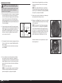
2. The recommended center of gravity (CG) location for your model
is 23/8–35/16 inches (60–85 mm) back from the leading edge of
the wing at the root. Mark the CG location on the wings with tape
or a marker. Balance your model upright with your fingers or a
balancing stand supporting the model at the marks made on the
bottom of the wing.
3. Support the aircraft upright at the marks made on the wing with
your fingers or a commercially available balancing stand.
If you are building the unpowered, tow launch version, proceed to
step 5.
4. If you are building the electric powered version, move the receiver
batteries forward or backward in the cockpit until the aircraft sits
level or slightly nose down on the balancing stand. When the proper
center of gravity is achieved, mount the receiver batteries to the
fuselage using hook and loop tape.
Proceed to the Control Throws section.
TIP: If the proper balance point cannot be achieved with the receiver
batteries fully forward, add self-adhesive weight until the aircraft
balances.
BALANCING THE AIRCRAFT
CAUTION: DO NOT SKIP THIS STEP. Never attempt to fly
without properly balancing the aircraft. An un-balanced aircraft
will be extremely unstable and may cause a crash. Crash damage is
not covered under warranty.
1. Attach the wing panels, canopy and tail surfaces to the fuselage.
Make sure to connect the leads from the aileron, flaps and spoilers
to the appropriate leads from the receiver. Make sure the leads are
not exposed outside the fuselage before tightening the wing bolts.
Your model should be powered OFF, in an otherwise flight-ready
state prior to balancing.
Add ballast to the nose of the aircraft until the fuselage sits level
or slightly nose-down on the balancing stand.
TIP: Tape a plastic bag to the outside of the nose of the fuselage
and add weight, such as lead shot or Deluxe Materials Liquid
Gravity (DLMBD38) to the bag until the aircraft balances.
5. Remove the wings, canopy and flight batteries from the fuselage,
and carefully stand the fuselage up on its nose.
6. Mix the ballast from step 5 with epoxy and micro balloons and add to
the inside of the nose of the fuselage. Allow the mixture to fully cure.
TIP: An alternative to adding the ballast directly to the fuselage
is to use the spinner from the Hangar 9 RV-4 (HAN488509) as a
mold to hold the epoxy/ballast mixture until it cures. This spinner
is an almost perfect match to the shape of the ASH nose. Pour the
ballast mixture into the spinner. After fully curing, the mixture can
be removed from the spinner and securely mounted in the nose of
the fuselage with epoxy.
Return the flight batteries to their position in the cockpit and
secure their location.
23/8–35/16 inches
(60–85 mm)

19 EN
ASH 31 6.4M ARF
PREFLIGHT CHECKLIST
• Charge the transmitter, receiver and motor batteries. Follow the instructions provided with the charger. Follow all
manufacturer’s instructions for your electronic components.
• Check the radio installation and make sure all control surfaces (aileron, elevator, rudder, flaps and spoilers) move
correctly (i.e., the correct direction and with the recommended throws).
• Check all the hardware (control horns, servo horns, and clevises) to make sure they are secure and in good condition.
• Prior to each flying session (and especially with a new model), perform a range check of your radio system. See your
radio manual for the recommended range and instructions for your particular radio system.
DAILY FLIGHT CHECKS
• Check the battery voltage of the transmitter battery. Do not fly below the manufacturer’s recommended voltage.
Doing so can cause your aircraft to crash.
• Check all hardware (linkages, screws, nuts, and bolts) prior to each day’s flight. Ensure that binding does not occur
and that all parts are properly secured.
• Ensure all surfaces are moving in the proper manner.
• Perform a ground range check before each day’s flying session.
• All servo leads and switch harness plugs should be secured in the receiver.
LIMITED WARRANTY
What this Warranty Covers
Horizon Hobby, LLC, (Horizon) warrants to the original purchaser that the product purchased (the “Product”) will be free from
defects in materials and workmanship at the date of purchase.
What is Not Covered
This warranty is not transferable and does not cover (i) cosmetic damage, (ii) damage due to acts of God, accident, misuse,
abuse, negligence, commercial use, or due to improper use, installation, operation or maintenance, (iii) modification of or to
any part of the Product, (iv) attempted service by anyone other than a Horizon Hobby authorized service center, (v) Product
not purchased from an authorized Horizon dealer, (vi) Product not compliant with applicable technical regulations, or (vii) use
that violates any applicable laws, rules, or regulations.
OTHER THAN THE EXPRESS WARRANTY ABOVE, HORIZON MAKES NO OTHER WARRANTY OR REPRESENTATION,
AND HEREBY DISCLAIMS ANY AND ALL IMPLIED WARRANTIES, INCLUDING, WITHOUT LIMITATION, THE IMPLIED
WARRANTIES OF NON-INFRINGEMENT, MERCHANTABILITY AND FITNESS FOR A PARTICULAR PURPOSE. THE PURCHASER
ACKNOWLEDGES THAT THEY ALONE HAVE DETERMINED THAT THE PRODUCT WILL SUITABLY MEET THE REQUIREMENTS
OF THE PURCHASER’S INTENDED USE.
Purchaser’s Remedy
Horizon’s sole obligation and purchaser’s sole and exclusive remedy shall be that Horizon will, at its option, either (i) service,
or (ii) replace, any Product determined by Horizon to be defective. Horizon reserves the right to inspect any and all Product(s)
involved in a warranty claim. Service or replacement decisions are at the sole discretion of Horizon. Proof of purchase is
required for all warranty claims. SERVICE OR REPLACEMENT AS PROVIDED UNDER THIS WARRANTY IS THE PURCHASER’S
SOLE AND EXCLUSIVE REMEDY.
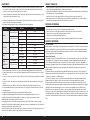
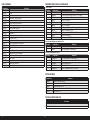
CONTROL THROWS
1. Turn on the transmitter and receiver of your model. Check the movement of the rudder using the transmitter.
When the stick is moved to the right, the rudder should also move right. Reverse the direction of the servo at the
transmitter if necessary.
2. Check the movement of the elevator with the radio system. Moving the elevator stick toward the bottom of the
transmitter will make the airplane elevator move up.
3. Check the movement of the ailerons with the radio system. Moving the aileron stick to the right will make the right
aileron move up and the left aileron move down.
4. Use a ruler to adjust the throw of the elevator, ailerons and rudder.
• In Landing or Soaring Mode, the ailerons will move independent from the flaperons.
• In Landing or Soaring Mode, droop the entire trailing edge (flaperons and ailerons) down 1/8–5/32 inches (3–4mm).
• In Cruise or Launch Mode, couple the ailerons and flaperons for full roll control.
• In Cruise or Launch Mode, reflex the entire trailing edge (flaperons and ailerons) up 1/8–5/32 inches (3–4mm).
• Use a slider to control the flaperon throw so the amount of travel can be varied.
• We recommend lowering the flaperons 3/8 inches (10mm) during Rise-Off-Ground (ROG) takeoffs and
during aero-tow.
• Set the rudder throw to an amount that will not bind the servo.
• Set the maximum flaperon throw to an amount that will not bind the servo.
These are general guidelines measured from our own flight tests. You can experiment with higher rates to match your
preferred style of flying.
Travel Adjust and Sub-Trims are not listed and should be adjusted according to each individual model and preference.
Always install the control horns 90 degrees to the servo center line. Use sub-trim as a last resort to center the servos.
Always re-binding the radio system once all of the control throws are set to keep the servos from moving to their
endpoints until the transmitter and receiver connect.
Surface Rate Direction Throw
Aileron
Landing/Soaring Up 5/8 inches (16mm)
Down 15/32 inches (12mm)
Cruise/Launch Up 11/16–13/16 inches (18–20mm)
Down 17/32 inches (14mm)
Elevator
High Up 11/32 inches (9mm)
Down 9/32 inches (7mm)
Low Up 9/32 inches (7mm)
Down 3/16 inches (5mm)
Rudder High Right 11/8–19/32 inches (35–45mm)
Left 11/8–19/32 inches (35–45mm)
Flaperon
Landing Down 1–13/16 inches (25–30mm)
Cruise/Launch Up 11/16–13/16 inches (18–20mm)
Down 17/32 inches (14mm)

20EN
WARRANTY AND SERVICE CONTACT INFORMATION
Country of
Purchase Horizon Hobby Contact Information Address
United States
of America
Horizon Service Center
(Repairs and Repair
Requests)
servicecenter.horizonhobby.com/
RequestForm/
2904 Research Road
Champaign, IL 61822
Horizon Product Support
(Product Technical
Assistance)
productsupport@horizonhobby.com
877-504-0233
Sales websales@horizonhobby.com
800-338-4639
European
Union
Horizon Technischer Service service@horizonhobby.eu Hanskampring 9
D 22885 Barsbüttel, Germany
Sales: Horizon Hobby GmbH +49 (0) 4121 2655 100
INSTRUCTIONS FOR DISPOSAL OF WEEE BY USERS IN THE EUROPEAN UNION
This product must not be disposed of with other waste. Instead, it is the user’s responsibility to dispose of their
waste equipment by handing it over to a designated collections point for the recycling of waste electrical and
electronic equipment. The separate collection and recycling of your waste equipment at the time of disposal
will help to conserve natural resources and ensure that it is recycled in a manner that protects human health
and the environment. For more information about where you can drop off your waste equipment for recycling,
please contact your local city office, your household waste disposal service or where you purchased the
product.
COMPLIANCE INFORMATION FOR THE EUROPEAN UNION
EU Compliance Statement: Horizon Hobby, LLC hereby declares that this product is in compliance with the
essential requirements and other relevant provisions of the EMC Directive.
A copy of the EU Declaration of Conformity is available online at:
http://www.horizonhobby.com/content/support-render-compliance.
Non-Warranty Service
Should your service not be covered by warranty, service will be completed and payment will be required without notification or
estimate of the expense unless the expense exceeds 50% of the retail purchase cost. By submitting the item for service you
are agreeing to payment of the service without notification. Service estimates are available upon request. You must include this
request with your item submitted for service. Non-warranty service estimates will be billed a minimum of ½ hour of labor. In
addition you will be billed for return freight. Horizon accepts money orders and cashier’s checks, as well as Visa, MasterCard,
American Express, and Discover cards. By submitting any item to Horizon for service, you are agreeing to Horizon’s Terms and
Conditions found on our website http://www.horizonhobby.com/content/service-center_render-service-center.
ATTENTION: Horizon service is limited to Product compliant in the country of use and ownership. If received, a
non-compliant Product will not be serviced. Further, the sender will be responsible for arranging return shipment
of the un-serviced Product, through a carrier of the sender’s choice and at the sender’s expense. Horizon will hold
non-compliant Product for a period of 60 days from notification, after which it will be discarded.
10/15
Limitation of Liability
HORIZON SHALL NOT BE LIABLE FOR SPECIAL, INDIRECT, INCIDENTAL OR CONSEQUENTIAL DAMAGES, LOSS OF PROFITS
OR PRODUCTION OR COMMERCIAL LOSS IN ANY WAY, REGARDLESS OF WHETHER SUCH CLAIM IS BASED IN CONTRACT,
WARRANTY, TORT, NEGLIGENCE, STRICT LIABILITY OR ANY OTHER THEORY OF LIABILITY, EVEN IF HORIZON HAS BEEN
ADVISED OF THE POSSIBILITY OF SUCH DAMAGES. Further, in no event shall the liability of Horizon exceed the individual price
of the Product on which liability is asserted. As Horizon has no control over use, setup, final assembly, modification or misuse,
no liability shall be assumed nor accepted for any resulting damage or injury. By the act of use, setup or assembly, the user
accepts all resulting liability. If you as the purchaser or user are not prepared to accept the liability associated with the use of
the Product, purchaser is advised to return the Product immediately in new and unused condition to the place of purchase.
Law
These terms are governed by Illinois law (without regard to conflict of law principals). This warranty gives you specific legal
rights, and you may also have other rights which vary from state to state. Horizon reserves the right to change or modify
this warranty at any time without notice.
WARRANTY SERVICES
Questions, Assistance, and Services
Your local hobby store and/or place of purchase cannot provide warranty support or service. Once assembly, setup or
use of the Product has been started, you must contact your local distributor or Horizon directly. This will enable Horizon to
better answer your questions and service you in the event that you may need any assistance. For questions or assistance,
please visit our website at www.horizonhobby.com, submit a Product Support Inquiry, or call the toll free telephone number
referenced in the Warranty and Service Contact Information section to speak with a Product Support representative.
Inspection or Services
If this Product needs to be inspected or serviced and is compliant in the country you live and use the Product in, please use
the Horizon Online Service Request submission process found on our website or call Horizon to obtain a Return Merchandise
Authorization (RMA) number. Pack the Product securely using a shipping carton. Please note that original boxes may be
included, but are not designed to withstand the rigors of shipping without additional protection. Ship via a carrier that
provides tracking and insurance for lost or damaged parcels, as Horizon is not responsible for merchandise until it arrives
and is accepted at our facility. An Online Service Request is available at http://www.horizonhobby.com/content/service-
center_render-service-center. If you do not have internet access, please contact Horizon Product Support to obtain a RMA
number along with instructions for submitting your product for service. When calling Horizon, you will be asked to provide
your complete name, street address, email address and phone number where you can be reached during business hours.
When sending product into Horizon, please include your RMA number, a list of the included items, and a brief summary of
the problem. A copy of your original sales receipt must be included for warranty consideration. Be sure your name, address,
and RMA number are clearly written on the outside of the shipping carton.
NOTICE: Do not ship LiPo batteries to Horizon. If you have any issue with a LiPo battery, please contact the
appropriate Horizon Product Support office.
Warranty Requirements
For Warranty consideration, you must include your original sales receipt verifying the proof-of-purchase date. Provided
warranty conditions have been met, your Product will be serviced or replaced free of charge. Service or replacement
decisions are at the sole discretion of Horizon.
La pagina si sta caricando...
La pagina si sta caricando...
La pagina si sta caricando...
La pagina si sta caricando...
La pagina si sta caricando...
La pagina si sta caricando...
La pagina si sta caricando...
La pagina si sta caricando...
La pagina si sta caricando...
La pagina si sta caricando...
La pagina si sta caricando...
La pagina si sta caricando...
La pagina si sta caricando...
La pagina si sta caricando...
La pagina si sta caricando...
La pagina si sta caricando...
La pagina si sta caricando...
La pagina si sta caricando...
La pagina si sta caricando...
La pagina si sta caricando...
La pagina si sta caricando...
La pagina si sta caricando...
La pagina si sta caricando...
La pagina si sta caricando...
La pagina si sta caricando...
La pagina si sta caricando...
La pagina si sta caricando...
La pagina si sta caricando...
La pagina si sta caricando...
La pagina si sta caricando...
La pagina si sta caricando...
La pagina si sta caricando...
La pagina si sta caricando...
La pagina si sta caricando...
La pagina si sta caricando...
La pagina si sta caricando...
La pagina si sta caricando...
La pagina si sta caricando...
La pagina si sta caricando...
La pagina si sta caricando...
La pagina si sta caricando...
La pagina si sta caricando...
La pagina si sta caricando...
La pagina si sta caricando...
La pagina si sta caricando...
La pagina si sta caricando...
La pagina si sta caricando...
La pagina si sta caricando...
La pagina si sta caricando...
La pagina si sta caricando...
La pagina si sta caricando...
La pagina si sta caricando...
La pagina si sta caricando...
La pagina si sta caricando...
La pagina si sta caricando...
La pagina si sta caricando...
La pagina si sta caricando...
La pagina si sta caricando...
La pagina si sta caricando...
La pagina si sta caricando...
La pagina si sta caricando...
La pagina si sta caricando...
La pagina si sta caricando...
La pagina si sta caricando...
-
 1
1
-
 2
2
-
 3
3
-
 4
4
-
 5
5
-
 6
6
-
 7
7
-
 8
8
-
 9
9
-
 10
10
-
 11
11
-
 12
12
-
 13
13
-
 14
14
-
 15
15
-
 16
16
-
 17
17
-
 18
18
-
 19
19
-
 20
20
-
 21
21
-
 22
22
-
 23
23
-
 24
24
-
 25
25
-
 26
26
-
 27
27
-
 28
28
-
 29
29
-
 30
30
-
 31
31
-
 32
32
-
 33
33
-
 34
34
-
 35
35
-
 36
36
-
 37
37
-
 38
38
-
 39
39
-
 40
40
-
 41
41
-
 42
42
-
 43
43
-
 44
44
-
 45
45
-
 46
46
-
 47
47
-
 48
48
-
 49
49
-
 50
50
-
 51
51
-
 52
52
-
 53
53
-
 54
54
-
 55
55
-
 56
56
-
 57
57
-
 58
58
-
 59
59
-
 60
60
-
 61
61
-
 62
62
-
 63
63
-
 64
64
-
 65
65
-
 66
66
-
 67
67
-
 68
68
-
 69
69
-
 70
70
-
 71
71
-
 72
72
-
 73
73
-
 74
74
-
 75
75
-
 76
76
-
 77
77
-
 78
78
-
 79
79
-
 80
80
-
 81
81
-
 82
82
-
 83
83
-
 84
84


Hangar 9 HAN3185 Manuale del proprietario
- Categoria
- Giocattoli telecomandati
- Tipo
- Manuale del proprietario
in altre lingue
- English: Hangar 9 HAN3185 Owner's manual
- français: Hangar 9 HAN3185 Le manuel du propriétaire
- Deutsch: Hangar 9 HAN3185 Bedienungsanleitung