
D4 U-BR1TE V W/PWR & DDS LOOPBACKS (U-BR1TE V)
DIP Switch SW5 Selects the following:
■ NORMAL or PTRN (SW5-1) for normal operation or test pattern generator for tests.
■ Channel B1 or B2 (SW5-2) selects either channel B1 or B2 for testing.
Pushbutton TEST Switch SW4
Depressing SW4 will initiate the test setup with SW2 and SW5. Refer to Status LEDs for test result indication. After initi-
ating a test, depressing SW4 a second time will inject a bit error into the data stream causing the ERR LED to flash. To
deactivate loopback tests, depress SW4 for 2 seconds (or position SW5-1 to NORMAL).
DEPLOYMENT GUIDELINES
■ All loops must be unloaded.
■ Actual Measured Loss (AML) should not exceed 40
dB at 40 kHz with 135 Ω termination, the Nyquist
frequency of IDSL.
■ Loop length should not exceed 18 kft.
■ Recommended bridged tap length should not
exceed 2 kft.
INSTALLATION & TURNUP
Installation assumes the network is up and running and
ready to accept the U-BR1TE V.
1. Wire T/R pair, pins 51 and 24, to the D4/SLC-96
backplane.
2. Select required/desired options on circuit board
switches SW1, SW3, and SW6.
3. Insert the U-BR1TE V into its designated slot ensuring the edge connector seats firmly into the backplane, observe
time slot allocation.
4. After insertion the U-BR1TE V will run a self-test during which all LEDs undergo an On/Off sequence.
5. After synchronization, which may take up to 90 seconds, the following LED indication will show:
■ ACT LED - Green (ISDN Application) Indicates activation bits have been successfully exchanged.
(DDS Application) Indicates loop terminated with an OCU-R.
■ All other LEDs will be Off until network occurrences cause them to turn On.
If LEDs in step 5 are as noted, proceed with loop testing per specifications.
If LEDs in step 5 are in any other configuration, refer to
TROUBLESHOOTING GUIDE.
SPAN POWER
The U-BR1TE V span powers the IDSL OCU-R or a U-Repeater. Voltage measurements from Tip to Ring is -120 VDC (with
no termination). Tip to GND is 0. Ring to GND is -120 VDC (with no termination) or less depending on voltmeter
impedance.
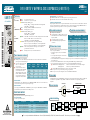
DDS APPLICATION
ISDN APPLICATIONS
JOBAID
61104020L4-22D
0205
U-BR1TE V
CLEI: D4C5BENB_ _
T-Carrier
Channel Bank
2-Wire Loop
4-Wire Customer
Interface
T/R Pair
Customer Premises
U-BR1TE
V
IDSL
OCU-R
DSU/CSU
Customer 4-Wire Qualifying IDSL Loss
Rate Frequency (kHz) Limit (dB)
2.4 1.2 14
2.4/SC 1.6 14.5
4.8 2.4 16
4.8/SC 3.2 17
9.6 4.8 19
9.6/SC 6.4 20.5
19.2 9.6 24
19.2/SC 12.8 27
56 28.0 35
56/SC & 64 36.0 36
STATUS LEDs
LP ●● OFF Loop synchronized, no errors.
(LOOP STATUS) ● RED U-interface out-of-sync, loss of signal.
● YELLOW Flashing = NEBE receipt, or
Flashing = BER >10
-6
during Local Performance Monitoring (LPM).
Solid = BER >10
-5
during LPM.
CR ●● OFF Framing established, no NEBEs from carrier interface.
(CARRIER STATUS) ● RED Framing pattern not received.
● YELLOW Flashing = NEBE receipt, or
Flashing = BER >10
-6
during LPM.
Solid = BER >10
-5
during LPM.
ACT ● GREEN Solid (ISDN) = Activation bits successfully exchanged between switch & CPE.
(ACTIVATION) Flash 1/sec (ISDN) = ACT bit sent in one direction only.
Solid (DDS) = Loop terminated by IDSL OCU-R.
TEST ● YELLOW Solid = Front panel test OK, or responding to 2B+D LBK.
Flash 1/sec = Response to B1 LBK request, or in front panel B1 LBK.
Flash 2/sec = Response to B2 LBK request, or in front panel B2 LBK.
● GREEN Solid = In local performance monitoring, or 2047 Test Pattern.
generation/detection invoked.
ERR ● RED Flashing = Errors seen by local Test Pattern Detector.
(Error)
CIRCUIT BOARD DIP SWITCHES
DIP Switch SW1 Selects the following:
■ Bank Type (SW1-1, SW1-2): D4, SLC I, or SLC III. Refer to the selection chart on the circuit board for
switch positions for desired bank type.
■ Service Level (SW1-3, SW1-4, and
SW1-5). See table shown for
service selection:
■ Zero Byte Substitution (SW1-6):
Enable/Disable ZBS. COT and RT
selection must match. Select
enabled for AMI, setting optional
for B8ZS. Disable in non-D chan-
nel (leased) modes at 64 kbps or
56 kbps with secondary channel.
DIP Switch SW3
Termination Mode (SW3-1: LULT-LUNT) (SW3-2: ADJACENT-TANDEM). Refer to the selection chart on the
circuit board for switch positions for required option settings.
Slide Switch SW6
Selects span power NORMAL (OFF), or POWER (ON) to power U-repeaters or IDSL OCU-R. The POWER
position should only be used when SW3-1 is in LULT position.
FRONT PANEL SWITCHES
Front panel switches are for selecting and initiating local tests.
Rotary Switch SW2
See table for position descriptions.
■ For a complete Installation and Maintenance Practice (P/N 61104020L4-5): (877) 457-5007, faxback Document 515. Please have your fax number ready. ■
Service Service SW1-3 SW1-4 SW1-5
Type Option (B1) (B2) (D)
ISDN 2B+D On On On
Leased 2B On On Off
ISDN/DDS B1+D On Off On
ISDN B2+D Off On On
DDS/Leased B1 On Off Off
Leased B2 Off On Off
Leased D Off Off On
INSERTION LOSS MEASUREMENTS
IDSL Design Limits at Traditional 4-Wire Frequencies.
Position Description Position Description
AD1
Address #1, address of this unit
AD6 Address #6, 5th downstream unit
AD2
Address #2, next downstream unit
LPBK Forces this unit into bidirectional loopback
AD3 Address #3, 2nd downstream unit CRTX Carrier transmit in carrier direction
AD4 Address #4, 3rd downstream unit LPTX Loop transmit in loop direction
AD5 Address #5, 4th downstream unit NT1 NT1 address latching OCU in DDS mode
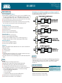
U-Repeater
ISDN
Switch
Customer Premises
U-BR1TE V
U-BR1TE V
U-BR1TE V
U-BR1TE V
U-BR1TE V U-BR1TE V
NT 1
Customer
Premises
NT 1
T1
“U”
“U”
“U” “U”
“U”
“U”
T1
T1
C A U T I O N
C A U T I O N
!
SUBJECT TO ELECTROSTATIC DAMAGE
OR DECREASE IN RELIABILITY.
HANDLING PRECAUTIONS REQUIRED.
#61104020L4-22D#

PRICING AND AVAILABILITY 800.827.0807
TECHNICAL SUPPORT 800.726.8663
RETURN FOR REPAIR 256.963.8722
www.adtran.com
61104020L4-22D
D4 U-BR1TE V
TROUBLESHOOTING GUIDE
No Power at the IDSL OCU-R or U-Repeater
■ Ensure U-BR1TE V is supplying necessary voltage to power U-repeater or IDSL OCU-R. Measure
T/R voltage at the frame (ring to GND = -118 to -122 VDC (with no termination), tip to ring = -118
to -122 VDC (with no termination), tip to GND = 0. The U-BR1TE V is not polarity sensitive.
■ If SW6 is in POWER position but voltage not present at downstream unit, check cable continuity.
■ If voltage is measured at the remote unit, replace the remote unit.
■ Neither the IDSL OCU-R nor the U-Repeater invoke a measurable short between tip and ring,
thus cable resistance measurements must be made with a manually applied short.
Power, but No Synchronization
■ ACT LED off - no sync with switch, check switch wiring.
■ ACT LED flashing - sync with switch only, check customer termination.
■ Check cable for load coils.
■ Check cable does not exceed 2 kft bridged tap.
■ Ensure loop length is within deployment guidelines.
Excessive Errors On Loop
■ Check cable does not exceed 2 kft bridged tap.
■ Ensure loop length is within deployment guidelines.
■ Compare resistance of individual conductors. If these are different, high resistance or
intermittent opens may be indicated. A TDR is commonly required to find such faults.
Excessive Errors On Carrier
■ Check channel bank configuration and timing.
■ Check near and far end U-BR1TE configuration.
Trouble Codes
In DDS mode the U-BR1TE V transmits an MOS (9Ah) trouble code towards the network under the
following fault conditions:
■ 2-wire DSL loss of signal.
■ Loss of synchronization.
■ Open loop.
■ The IDSL OCU-R transmits an ASC (9Eh) trouble code towards the network from the customer
premises for similar 4-wire customer interface fault conditions.
■ ASC (9Eh) is transmitted to the network in B1 during loopback conditions initiated by the IDSL
OCU-R.
TESTING
The U-BR1TE V supports the following loopbacks and tests:
■ Embedded operation channel when the D-channel is On (D, B1/B2+D, 2B+D)
■ DS0 DP latching loopback sequences in B1 when D-channel is Off (B1, 2B).
■ eoc remapping of subsequent DS0 DP latching loopbacks to downstream elements.
■ Front panel initiated tests using SW2 for test selection, SW5 for channel selection and pattern
generator, and TEST pushbutton SW4 to initiate the test. Tests include the following:
• Loopback Tests (ADR1 through ADR 6 plus NT1)
• Point-to-Point (CRTX, LPTX)
• Local Loopback (LPBK)
• Local Performance Monitoring via rotary switch and LBK pushbutton.
■ Externally initiated tests via front panel bantam jacks and test set.
■ Remote initiated tests from the CO, test center, or IDSL OCU-R.
LBK & Pushbutton Tests (U-BR1TE must be ADTRAN for Loopback Response from OCU-R.)
Successful loopback tests initiated by the TEST/LBK pushbuttons will show the LED indications
listed and will transmit the trouble codes shown.
WARRANTY
Warranty for Carrier Networks products manufactured by ADTRAN and supplied under Buyer’s
order for use in the U.S. is ten (10) years. For a complete copy of ADTRAN’s
U.S. and Canada
Carrier Networks Equipment Warranty
, P/N 60000087-10, call: (877) 457-5007, faxback
Document 414.
COMPLIANCE REQUIREMENTS
Max input current @ max load = 750 mA @ -48 VDC.
Max output current @ max load = 160 mA @ -137 VDC.
CAUTION: This product for installation in a restricted
access location in a Type B or E enclosure only.
Code Input Output
Power Code (PC) F C
Telecommunication Code (TC) – X
Installation Code A –
-
 1
1
-
 2
2


in altre lingue
- English: ADTRAN D4 U-BR1
Altri documenti
-
 Dolby Laboratories All in One Printer DP503 Manuale utente
-
Juniper J6350 Getting Started Manual
-
Multitech MultiModemII Manuale utente
-
ADC Network Card EMU-830 Manuale utente
-
RKC INSTRUMENT COM-ME-1 Manuale utente
-
-
Philips Xenium 9@9 Guida utente
-
Videotec DTRX3 Manuale utente
-
-
