
User manual for art. 2012-2014-1710-1711-1712
Manuale d’uso per art. 2012-2014-1710-1711-1712
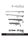
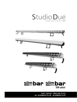
PLUS
PLUS

2
Rel.1 - 10/2020
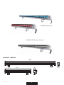
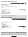
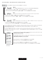
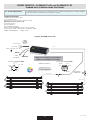
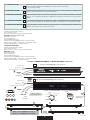
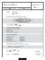
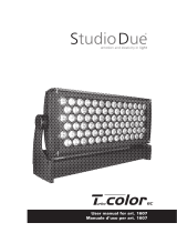
1005
525 40
60
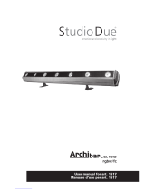
PHYSICAL / MISURE
SLIMBAR PLUS rgbw
SLIMBAR PLUS monochromatic

3Rel.1 - 10/2020
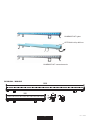
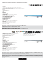
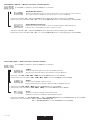
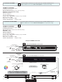
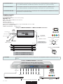
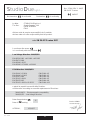
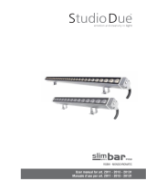
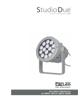
PHYSICAL / MISURE
SLIMBAR FLAT monochromatic
1000
500 46
30,5
48
SLIMBAR FLAT rgbw
OPTIONAL milky diffuser

4
Rel.1 - 10/2020
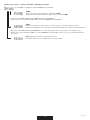
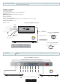
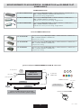
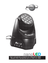
,I\RXZDQWWRFRQQHFWWKH¿[WXUHVIRU
OUTDOORXVH\RXFDQPDNHDQHZ
FDEOHXWLOL]LQJWKLVFRQQHFWRUV
7KHFDEOHLVQRWLQFOXGHGZLWKWKH
FRQQHFWRUVNLW
6HYROHWHXWLOL]]DUHJOLDSSDUHFFKL
all’ESTERNO, SRWHWHUHDOL]]DUHGHL
QXRYLFDYLFRQTXHVWLFRQQHWWRUL
,OFDYRQRQqLQFOXVRQHONLWGHLFRQQHWWRUL
art. 5PIN IP67 CONNECTORS
LQFOXGHGZLWKWKH¿[WXUHLQFOXVRQHOO¶DSSDUHFFKLR
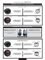
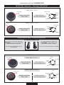
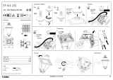
IN/OUT IP67 connectors - Connettori IP67 IN/OUT
MONOCHROMATIC fixture
+48VDC
input connector
front view
output connector
front view
input connector
rear side welding view
MALE - INPUT connector
FEMALE - OUTPUT connector
output connector
rear side welding view
RGBW fixture
input connector
front view
output connector
front view
input connector
rear side welding view
MALE - INPUT connector
FEMALE - OUTPUT connector
output connector
rear side welding view
+48VDC
- WHITE
+48VDC
IN MALE
CONNECTOR
+48VDC
+48VDC
- WHITE
+48VDC
OUT FEMALE
CONNECTOR
IN MALE
CONNECTOR
- BLUE - GREEN
- WHITE - RED
+48VDC
OUT FEMALE
CONNECTOR
- BLUE
- WHITE
- GREEN
- RED
+48VDC
- WHITE
- WHITE
- RED
- RED
connectors only for SLIMBAR PLUS

5Rel.1 - 10/2020
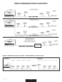
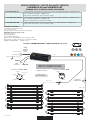
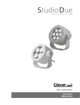
,I\RXZDQWWRFRQQHFWWKH¿[WXUHVIRU
OUTDOORXVH\RXFDQPDNHDQHZ
FDEOHXWLOL]LQJWKLVFRQQHFWRUV
7KHFDEOHLVQRWHQGRZHGZLWKWKH
FRQQHFWRUVNLW
6HYROHWHXWLOL]]DUHJOLDSSDUHFFKL
all’ESTERNO, SRWHWHUHDOL]]DUHGHL
QXRYLFDYLFRQTXHVWLFRQQHWWRUL
,OFDYRQRQqLQFOXVRQHONLWGHLFRQQHWWRUL
art. 5PIN IP67 CONNECTORS
HQGRZHGZLWKWKH¿[WXUHLQFOXVRQHOO¶DSSDUHFFKLR
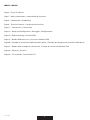
IN/OUT IP67 connectors - Connettori IP67 IN/OUT
MONOCHROMATIC fixture
+52VDC / WHITE
- CH3 WHITE
+52V / WHITE
input connector
front view
+52V / WHITE
output connector
front view
input connector
rear side welding view
MALE - INPUT connector
FEMALE - OUTPUT connector
- CH4 WHITE
+52VDC / WHITE
- CH1 WHITE
output connector
rear side welding view
RGBW fixture
+52VDC / RGBW
input connector
front view
output connector
front view
input connector
rear side welding view
MALE - INPUT connector
FEMALE - OUTPUT connector
- RED - BLUE
- GREEN
+52VDC / RGBW - WHITE
+52VDC /
RGBW
output connector
rear side welding view
- GREEN
- BLUE - RED
- CH3 WHITE
- CH2
WHITE
- CH4 WHITE
- CH3 WHITE
- CH2
WHITE
+52VDC /
RGBW
- WHITE
1
2
3
4
5
5
4
3
2
1
1
2
3
4
5
5
4
3
2
1
connectors only for SLIMBAR FLAT

6
Rel.1 - 10/2020
INDEX / INDICE
Page 2 - Physical / Misure
Page 7 - Safety informations / Informazioni di sicurezza
Page 8 - Introduction / Introduzione
Page 9 - Technical features / Caratteristiche tecniche
Page 11 - Connections / Connessioni
Page 13 - Setup and Configuration / Settaggio e Configurazione
Page 14 - DRS functioning / Funzioni DRS
Page 15 - Slimbar DRS menu list / Lista menu Slimbar DRS
Page 20 - Example of connection DMX controller-driver / Esempio di collegamento centralina DMX-driver
Page 21 - Slimbar Pilot example of connections / Esempi di connessioni Slimbar Pilot
Page 28 - Warranty / Garanzia
Page 29 - CE standards / Certificazioni CE

7Rel.1 - 10/2020
eng
WARNING
!SAFETY INFORMATION (service personnel)
READ ALL CAUTIONS AND WARNINGS PRIOR TO OPERATE THIS EQUIPMENT.
INSTRUCTION TO PREVENT INJURY OR DAMAGE DUE TO ELECTRIC SHOCK, FIRE, MECHANICAL HAZARDS,
DANGEROUS MATTERS.
•PROTECTION AGAINST FIRE
1) Maintain minimum distance of 0,1 meter to lighted objects.
2) Replace fuses (if present) only with the specified type and rating.
3) Do not install the fixture close to heat sources. Do not lay the connection cable on the fixture when it is warm.
4) Fixture designed to be installed on normally flammable surfaces.
•PROTECTION AGAINST ELECTRIC SHOCK
1) This equipment must be earthed.
2) Class I equipment. The power supply cord includes a protective earthing conductor as part of the cord.
3) Disconnect power before servicing (service personnel).
4) To replace the LEDs, contact: Studio Due Trade Srls.
5) If the external flexible cable of this appliance is damaged, it must only be replaced by the manufacturer,
its assistance service, or equivalent qualified personnel, in order to avoid dangers.
•PROTECTION AGAINST MECHANICAL HAZARDS
1) Use secondary safety chain when fixing this equipment.
2) The protection screens and the lenses must be replaced with genuine parts only if they are visibly damaged and
their effectiveness has been reduced, for example, by cracks or deep scratches.
3) Do not look directly into the illuminated LEDs of the product for long periods of time. LED lamps can cause eye
damage or irritation. Do not look directly into the light source using an optical instrument that focuses on
the light beams.
The device should be positioned so that there is no prolonged observation of the device at a distance
of less than 100cm. (RG1 – IEC/TR 62778:2014).
•PROTECTION AGAINST DANGEROUS MATTERS
At the end of its life, must be collected separately. It shouldn’t be thrown as urban waste and neither released in the
environment.
It must be collected from the nearest special waste collection point or consigned to your dealer that provides the servi-
ce. The incorrect waste disposal can damage the environment and the people for the presence of dangerous substan-
ces. Sanctions are provided for an unauthorized disposal.
INFORMAZIONI DI SICUREZZA (personale di servizio)
LEGGERE ATTENTAMENTE TUTTI GLI AVVERTIMENTI PRIMA DI COMPIERE QUALUNQUE OPERAZIONE SU QUESTO
APPARECCHIO. ISTRUZIONI PER PREVENIRE LESIONI O DANNI DOVUTI AL FUOCO, ALLE SCOSSE ELETTRICHE,
AI RISCHI MECCANICI ED A SOSTANZE PERICOLOSE.
•PROTEZIONE CONTRO IL FUOCO
2) Mantenere la distanza minima di 0,1 metri dagli oggetti illuminati.
3) Sostituire i fusibili (se presenti) solo con altri dello stesso tipo e valore.
4) Non installare il faro vicino fonti di calore. Non appoggiare il cavo di connessione sul faro quando questo è caldo.
5) Questo apparecchio è adatto per il montaggio su superfici normalmente infiammabili.
•PROTEZIONE CONTRO SCOSSE ELETTRICHE
1) Questo apparecchio necessita di messa a terra.
2) Apparecchio di Classe I. Il conduttore di protezione deve far parte del cavo di alimentazione.
3) Disconnettere l’alimentazione prima di aprire l’apparecchio (personale di servizio).
•PROTEZIONE CONTRO RISCHI MECCANICI
1) Usare la catena di sicurezza supplementare quando installate il faro.
2) Gli schermi di protezione e le lenti devono essere sostituiti sempre con ricambi originali
se sono visibilmente danneggiati e se la loro efficacia è stata ridotta, per esempio, da fessure o incisioni profonde.
3) Non guardare direttamente nei LED illuminati del prodotto per lunghi periodi di tempo. Le lampade a LED possono
causare danni o irritazione agli occhi. Non guardare direttamente nella sorgente luminosa utilizzando uno strumento
ottico che si concentra sui fasci di luce. L’apparecchio dovrebbe essere posizionato in modo che non sia prevista
un’osservazione prolungata dell’apparecchio ad una distanza inferiore di 100cm. (RG1 – IEC/TR 62778:2014).
IMPORTANTE
!
•PROTEZIONE CONTRO SOSTANZE PERICOLOSE
A fine vita è oggetto di raccolta separata, non gettare nei comuni cassonetti di rifiuti urbani, né tantomeno nell’am-
biente. Può essere consegnato presso gli appositi centri di raccolta differenziata predisposti dalle amministrazioni
comunali, oppure presso i rivenditori che forniscono questo servizio. Lo smaltimento errato può causare danni alle
persone e all’ambiente per la possibile presenza di sostanze pericolose. Sono previste sanzioni in caso di smaltimen-
to abusivo dei suddetti prodotti.
ita

8
Rel.1 - 10/2020
INTRODUCTION
Thanks for using SLIMBAR FLAT / SLIMBAR PLUS, an ultra small form factor LED LINEAR BAR with IP67 rating protection.
This kind of LED bar series is suitable for accent lighting.
Available in two light source:
- RGBW with high efficiency RGBW LEDs
- MONOCHROMATIC or WHITE BALANCE with monochromatic high efficiency LEDs.
Available in 2 different measures, 100cm. and 50cm. Standard fixture finishing is grey.
• Art. 1710: SLIMBAR FLAT/RGBW
• Art. 1711: SLIMBAR FLAT/WB (white balance)
• Art. 1712: SLIMBAR FLAT/M (monochromatic)
• Art. 2012: SLIMBAR PLUS/RGBW (differs from Slimbar Flat for the use of optics)
• Art. 2014: SLIMBAR PLUS/W (differs from Slimbar Flat for the use of optics)
To make the most of its possibilites and for a correct functioning of this unit in the years to come, we suggest you to read carefully this
manual before connecting or putting the spot into use. By doing so you will gain experience with its commands and connections and
you will be easily able to use it.
INTRODUZIONE
Vi ringraziamo per l’utilizzo di SLIMBAR FLAT / SLIMBAR PLUS, la nostra LED LINEAR BAR ultra compatta con protezione IP67.
Questa serie di LED linear bar è adatta per l’illuminazione d’accento.
Disponibile in due sorgenti di luce:
- RGBW con LEDs RGBW ad alta efficienza
- MONOCROMATICA o WHITE BALANCE con LEDs monocromatici ad alta efficienza
Disponibile in 2 misure, 100 cm. e 50 cm. Finitura standard è colore grigio.
• Art. 1710: SLIMBAR FLAT/RGBW
• Art. 1711: SLIMBAR FLAT/WB (white balance)
• Art. 1712: SLIMBAR FLAT/M (monochromatic)
• Art. 2012: SLIMBAR PLUS/RGBW (si differenzia da Slimbar Flat per l’uso di ottiche)
• Art. 2014: SLIMBAR PLUS/W (si differenzia da Slimbar Flat per l’uso di ottiche)
Per ottenere il meglio delle prestazioni ed un corretto funzionamento negli anni di questa unità, Vi consigliamo di leggere attentamente
questo manuale prima di collegarla e metterla in uso. In questo modo acquisirete familiarità con i suoi comandi e collegamenti affinché
possiate facilmente utilizzarla.
eng
YOUR REFERENCE
Always remeber to give the serial number and to specify the model any time you address the seller for information or assistance.
BASIC KIT
• Projector
• User’s manual
• CE standard
• Studio Due warranty WARNING
!
Check that the fixture has not been damaged during transport. If it has been damaged or
it does not work, address the seller. Whether the fixture has been shipped to you directly,
please contact the shipping company.
Only the consignee (person or company) can claim for these damages.
VOSTRA REFERENZA
Citate il numero del modello e di serie ogni volta che Vi rivolgete al vostro rivenditore per informazioni o assistenza.
CONFEZIONE BASE
• Proiettore
• Manuale d’uso
• Dichiarazione CE
• Garanzia Studio Due
Controllate che l’apparecchio non abbia subito alcun danno durante il trasporto.
Se avesse subito dei danni o se non dovesse funzionare, rivolgetevi al vostro rivenditore.
Se l’apparecchio vi è stato spedito direttamente, rivolgetevi subito alla ditta di trasporto.
Solo il destinatario (la persona o ditta ricevente l’apparecchio) può reclamare per questo
tipo di danni.
IMPORTANTE
!
ita

9Rel.1 - 10/2020
SLIMBAR PLUS TECHNICAL FEATURES / CARATTERISTICHE TECNICHE
• SOURCE
28 RGB-NW (white 4000K) LEDs (n.14 for 50cm.)
Lumen: R 460, G 950, B 260, CW 1000 (R 230, G 475, B 130, CW 500 for 50cm.)
Total light power: 32W (16W for 50cm.)
• OPTIC
24° (23mm lenses) PMMA 8N and ultra white tempered glass
On request: 12°, 36°, 10°x30°, 15°x55°, holographic filter 10°x80° to match with narrow beam
• TILT
Manual 200°
• CONTROL
n.4 Channels 48VDC
• CONNECTIONS
n.2 connectors 5pin IP 67 (male-female) cable 40cm.
possibility to link up to 5 devices in chain
• SETUP AND CONFIGURATION
To drive SLIMBAR PILOT RGBW use SLIMBAR-F Pilot
• IP 67 RATING PROTECTION
• POWER CONSUMPTION
42W (21W for 50cm.)
• POWER SUPPLY
48VDC - this fixture has to work with SLIMBAR-F Pilot
• PHYSICAL
WxDxH: 1005x40x60 mm (dimension of profile)
WxDxH: 525x40x60 mm (dimension of profile)
Weight: 1 Kg. or 0,5 Kg.
This fixture can only work connected to the dedicated DMX driver:
SLIMBAR PILOT-F DRS or SLIMBAR PILOT-F PLUS.
Questo apparecchio funziona solo collegato ad un driver DMX dedicato:
SLIMBAR PILOT-F DRS or SLIMBAR PILOT-F PLUS.
Thist fixture must be connected to the dedicated DMX driver: SLIMBAR PILOT-F DRS or SLIMBAR PILOT-F PLUS.
A voltage with an higher tolerance than specified may cause malfunction or damage.
L’apparecchio deve essere collegato ad un driver DMX dedicato: SLIMBAR PILOT-F DRS or SLIMBAR PILOT-F PLUS.
Una tensione di alimentazione con tolleranza maggiore di quella indicata può causare malfunzionamenti e danneggiare irrepara-
bilmente l’apparecchio.
• SOURCE
n.30 LED NICHIA NVSLE21AT (4000K) (n.15 for 50cm.)
Total out lumen: 1800lm (900lm for 50cm.)
Total light power: 12W (6W for 50cm.)
• OPTIC
24° (23mm lenses) PMMA 8N and ultra white tempered glass
On request: 12°, 36°, 10°x30°, 15°x55°, holographic filter 10°x80° to match with narrow beam
• TILT
Manual 200°
• CONTROL
Constant Voltage 48VDC
• CONNECTIONS
n.2 connectors 5pin IP 67 (male-female) cable 40cm.
possibility to link up to 10 devices in chain
• SETUP AND CONFIGURATION
To drive SLIMBAR/W use SLIMBAR Pilot
• IP 67 RATING PROTECTION
• POWER SUPPLY (the fixture has to work with SLIMBAR Pilot)
13W (7W for 50cm.)
• PHYSICAL
WxDxH: 1005x40x60 mm (dimension of profile)
WxDxH: 525x40x60 mm (dimension of profile)
Weight: 1 Kg. or 0,5 Kg.
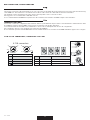
WW W
warm neutral cool 12°
OPTICS
24°
OPTICS
36°
OPTICS
10°x30°
OPTICS
15°x55°
OPTICS
holographic
FILTER IP
67 external
PSU LED RDM
RGBW
8°
OPTICS
12°
OPTICS
24°
OPTICS
36°
OPTICS
10°x30°
OPTICS
15°x55°
OPTICS
holographic
FILTER IP
67 external
PSU LED RDM

10
Rel.1 - 10/2020
• SOURCE (monochromatic)
n. 112 warm, neutral or cool White LEDs (n.56 for 50cm.)
on request: red, blue, green or amber LEDs
Lumen: 5000 (2500 for 50cm.)
Total light power: 35W (17W for 50cm.)
• OPTIC
- 120° no lenses
- optional: milky diffuser
• TILT
Manual 160°
• CONTROL
n.4 Channels 48-52VDC
• CONNECTIONS
n.2 connectors 5pin IP 67 (male-female) cable 40cm.
possibility to link up to 5 devices in chain
• SETUP AND CONFIGURATION
To drive SLIMBAR FLAT use SLIMBAR-F Pilot
• IP 67 RATING PROTECTION
• POWER CONSUMPTION
42W (21W for 50cm.)
• POWER SUPPLY
52VDC - this fixture has to work with SLIMBAR-F Pilot
• PHYSICAL
WxDxH: 1000x35x40 mm (dimension of profile)
WxDxH: 500x35x40 mm (dimension of profile)
Weight: 1 Kg. or 0,5 Kg.
• SOURCE
n. 28x4 Red, Green, Blue, White mid power LEDs (n.14x4 for 50cm.)
Lumen: R 460, G 950, B 260, CW 1300 (R 230, G 475, B 130, CW 650 for 50cm.)
Total light power: 32W (16W for 50cm.)
• OPTIC
- 120° no lenses
- optional: milky diffuser
• TILT
Manual 160°
• CONTROL
n.4 Channels 52VDC
• CONNECTIONS
n.2 connectors 5pin IP 67 (male-female) cable 40cm.
possibility to link up to 5 devices in chain
• SETUP AND CONFIGURATION
To drive SLIMBAR FLAT use SLIMBAR-F Pilot
• IP 67 RATING PROTECTION
• POWER CONSUMPTION
42W (21W for 50cm.)
• POWER SUPPLY
52VDC - this fixture has to work with SLIMBAR-F Pilot
• PHYSICAL
WxDxH: 1000x35x40 mm (dimension of profile)
WxDxH: 500x35x40 mm (dimension of profile)
Weight: 1 Kg. or 0,5 Kg.
SLIMBAR FLAT TECHNICAL FEATURES / CARATTERISTICHE TECNICHE
RGBW
120°
OPTICS IP
67 external
PSU LED
This fixture can only work connected to the dedicated DMX driver:
SLIMBAR PILOT-F DRS or SLIMBAR PILOT-F PLUS.
Questo apparecchio funziona solo collegato ad un driver DMX dedicato:
SLIMBAR PILOT-F DRS or SLIMBAR PILOT-F PLUS.
Thist fixture must be connected to the dedicated DMX driver: SLIMBAR PILOT-F DRS or SLIMBAR PILOT-F PLUS.
A voltage with an higher tolerance than specified may cause malfunction or damage.
L’apparecchio deve essere collegato ad un driver DMX dedicato: SLIMBAR PILOT-F DRS or SLIMBAR PILOT-F PLUS.
Una tensione di alimentazione con tolleranza maggiore di quella indicata può causare malfunzionamenti e danneggiare irrepara-
bilmente l’apparecchio.
120°
OPTICS LED
IP
67
BGR A
WW W
warm neutral cool2900K 6000K
external
PSU
optional
DALI
optional
• SOURCE (white balance)
n. 56 (2900K) +56 (6000K) White LEDs (n.28 + n.28 for 50cm.)
Lumen: 2300 + 2600 (1150 + 1300 for 50cm.)
Total light power: 35W (17W for 50cm.)

11 Rel.1 - 10/2020
CONNECTIONS / CONNESSIONI
The SLIMBAR PILOT-F must be earthed.
Class I equipment. The power supply cord includes a protective earthing conductor as part of the cord.
IMPORTANT: to ensure the IP67 protection rating, in case of replacement of the conductor cable, refer to the CONDUCTOR SIZE TABLE
SLIMBAR PILOT-F necessita di messa a terra.
Apparecchio di Classe I. Il conduttore di protezione deve far parte del cavo di alimentazione.
IMPORTANTE: per garantire il grado di protezione IP67, in caso di sostituzione del cavo di alimentazione, fare riferimento alla
TABELLA SEZIONE CONDUTTORE.
eng
ita
WARNING
!
IMPORTANTE
!
CONDUCTOR SIZES / SEZIONE CONDUTTORE
(length / lunghezza < 20mt.)
MAINS VOLTAGE CROSS SELECTIONAL AREAS
230V 3X1 mm2 (minimum)
MAIN POWER/
INGRESSO ALIMENTAZIONE
Ø 6 - 12mm
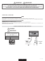
(;$03/(2)0$,132:(5RU'0;&211(&7,21
DMX
OUT
DMX
IN
'0;FDEOHV
IP 67
UDWLQJ
SURWHFWLRQ
MAIN
POWER
brown/marrone
blu neutral
yellow green/giallo verde
THE EQUIPMENT IS SUPPLIED WITH A POWER-IN AND A POWER-OUT CONNECTORS WITH CABLE 40CM. LONG.
DO NOT CUT THE CABLES, USE THE SUPPLIED CONNECTORS FOR EXTENSIONS.
L’APPARECCHIO È FORNITO DI UN CAVO LUNGO 40CM. CON CONNETTORE POWER-IN E DI UNO POWER-OUT.
NON TAGLIARE I CAVI, UTILIZZARE I CONNETTORI IN DOTAZIONE PER I PROLUNGAMENTI.
IMPORTANT
!IMPORTANTE
!
DOOW\SHV

12
Rel.1 - 10/2020
DMX TERMINAL LINE
The wrong connection of the terminal line or its non-connection are probably the most frequent reasons for the defective functioning
of the DMX line. The terminator is a terminal resistor fitted at the end of the cable furthest from the transmitter.
The terminal resistor should have the same value as the impedance of the connection cable.
We suggest to use a terminal with a 120 Ohm resistor.
It is recommanded that all DMX 512 systems have the terminal resistor fitted in the DMX output of the last fixture.
TERMINALE LINEA DMX
L’incorretto o il mancato collegamento del terminale di linea è probabilmente la più comune causa del difettoso funzionamento della
linea DMX. Il terminale di linea DMX consiste in una resistenza posta alla fine della linea.
La resistenza terminale dovrebbe avere idealmente lo stesso valore dell’impedenza del cavo di collegamento.
Noi consigliamo di usare come terminale una resistenza da 120 Ohm.
E’ raccomandato per tutti i sistemi DMX 512 inserire il teminale di linea nel connettore uscita DMX dell’ultimo apparecchio collegato.
eng
ita
DMX CONNECTION / CONNESSIONE DMX
4 PIN and XRL CONNECTORS / CONNETTORI 4 PIN e XRL
Termination resistor
Terminale di linea
120 Ohm
PIN LANGISERIW
NIP SIGNAL
1
1
SHIELD GROUND/RETURN/OV
GROUND/RETURN/OV
N.C.
2)DETREVNI,-(TNEMELPMOCATADROTCUDNOCRENNI
2
DATA COMPLEMENT ( -, INVERTED)
3
3
4
or
INNER CONDUCTOR DATATRUE ( +, NON INVERTED)
DATATRUE ( +, NON INVERTED)
DMX inputDMX output Termination resistor
Terminale di linea
120 Ohm
Termination resistor
Terminale di linea
120 Ohm
DMX input
MALEFEMALE
4 or
4
1
1
3
4 or
23
32
DMX output
4 PIN connectors

13 Rel.1 - 10/2020
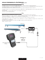
SETUP and CONFIGURATION by DRS - DMX REMOTE SETUP
SETTAGGIO e CONFIGURAZIONE tramite DRS - DMX REMOTE SETUP
The DRS it’s a new concept of professional LED Lighting fixtures suitable for outdoor permanent installations.
The LED Lighting fixtures can be driven via DMX through a specific electronic device, the DRS DMX Remote Setup, that grant the
possibility to set up the scenarios and the games remotely.
These LED Lighting fixtures have installed on board a series of programs including the stand alone function.
The DRS is a simple set up commander that linked with the DMX input of a LED Lighting fixture allow to program all the functions
of the luminaire.
It’s than possible to assign the DMX channel or use the Master/Slave function.
The device is powered through battery.
DMX line
connector
MAIN Power
and
Powered through
battery
DRS è il nuovo concetto dell’illuminazione LED per uso professionale nelle installazioni esterne permanenti.
Gli apparecchi LED possono essere controllati e configurati tramite uno specifico controller: il DRS, DMX Remote Setup, il quale
consente di programmare e configurare scene e giochi di luce in modalità remota.
Questi apparecchi LED hanno installati a bordo una serie di giochi che includono la funzione stand alone.
Il DRS, DMX Remote Setup, è un semplice set-up commander che collegato via DMX ad un’apparecchio consente la sua
programmazione e configurazione.
E’ possibile assegnare agli apprecchi collegati i canali DMX o utilizzazre la funzione Master/Slave.
Il DRS è alimentato a batterie.
eng
ita
DOOW\SHV
MAIN
DMX
SLIMBAR FLAT
SLIMBAR PLUS

14
Rel.1 - 10/2020
FUNZIONAMENTO DI BASE DEL DRS (DMX Remote Setup)
Per effettuare la programmazione dei vari parametri di un apparecchio, è necessario procedere come segue:
• Disconnettere l’apparecchio da configurare da altri dispositivi DMX/RDM
• Collegare il cavo DMX dell’apparecchio da configurare, al programmatore DRS
• Accendere il programmatore DRS (spingere uno dei pulsanti) ed attendere che visualizzi la scritta 8888
• Se il programmatore DRS individua un dispositivo DRS compatibile, visualizza per qualche istante la scritta
Conn e, successivamente, visualizza il nome dell’apparecchio e la relativa versione software
• Se il programmatore DRS non individua alcun dispositivo DRS compatibile o è presente qualche
malfunzionamento il display visualizzerà la scritta SCAn
• Una volta terminata la sequenza di riconoscimento, viene visualizzato il primo menu dell’apparecchio
• I pulsanti UP/DOWN permettono di scorrere la lista dei menu
• Il pulsante ENTER permettere di entrare in un menu o di confermare una opzione in caso di lampeggio del parametro
• Il pulsante ESC annulla una operazione o torna al livello di menu inferiore.
ita
DRS (DMX Remote Setup) FUNCTIONING
To make the set-up of the various fixture parameter, proceed as follow:
•Disconnect the fixture to set-up from the other DMX/RDM devices
• Connect the DMX cable of the fixture to the DRS commander
• Switch on the DRS (push any button) commander and wait for the 8888 sign
• If the DRS commander detects a compatible DRS device, displays shortly the Conn written and afterwards,
displays the name of the fixture and its software version.
• If the DRS commander dont’ detects any compatible DRS device or is present any malfunction, the display
shows the SCAn written
• When the detection sequence is finished, the display shows the first menu
• The UP/DOWN buttons allow to scroll forward/backward the menu list
• The ENTER button allow to confirm the selected option (if the parameter is flashing)
• The ESC button allow to delete the operation and return to a previus menu level
eng

15 Rel.1 - 10/2020
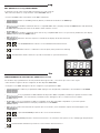
Switching on the fixture you can see the model and the software version. For example:
All’accensione, viene visualizzato il modello di apparecchio e la versione software. Per esempio:
--> Slimbar rGbW --> 2_00
than it’s shown the fist menu
poi viene visualizzato il primo menu
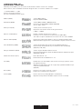
Address (Addr) Set the DMX address
Imposta l’indirizzo DMX
Auto Mode (ModE) Set the DMX, SLAVE or MASTER mode
Imposta la modalità DMX, SLAVE o MASTER
(no, SL, Pr01…Prxx)
Auto Speed (PrSP) Set the preset execution speed
Imposta la velocità di esecuzione dei giochi interni
( -400%…+400%)
Wireless enable (ULEn) Enable or disable the wireless reception
Consente o non consente la ricezione wireless (ON / OFF)
The cable reception is disabled / La ricezione via cavo viene disabilita
Wireless unlink (ULPA) Remove the link from the fixture to the associated transmitter (PA?)
Elimina il link tra l’apparecchio e il trasmettitore al quale è stato associato
Smooth Dimming (SMth) Set the interpolation type for the smooth dimming function
Imposta il tipo di interpolazione per la funzione smooth dimming
(OFF, Sd1, Sd2, Sd3)
Halogen Simulation (HALS) Set the alogen simulation function mode
Imposta il funzionamento della modalità simulazione lampada alogena
(OFF, Mod1, Mod2)
Flicker free function (FLcr) Select the value f1 .. f2
Selezionate il valore desidarato f1 .. f2
Test (tESt) Enables the test of the fixture and execute a factory program to check
the right functioning
Abilita il test dell’apparecchio ed esegue un programma di fabbrica per
verificarne il funzionamento
(OFF, On)
Reset (rSEt) Execute a reset of the electronic section
Esegue un reset della parte elettronica
Format (FrMt) Restore the factory setting (Require confirmation)
Ripristina le impostazioni di fabbrica (Viene chiesta conferma)
SLIMBAR DRS MENU’ LIST
ELENCO MENU’ SLIMBAR DRS

16
Rel.1 - 10/2020
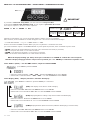
If you want to enter into setup mode, you must follow the start procedure:
Se desiderate entrare nella modalità setup, dovete seguire la procedura di accesso:
Press keys in sequence / Premere i tasti in sequenza:
ENTER >> UP >> DOWN >> ESC
MENU LIST and BUTTON FUNCTIONS - ELENCO MENU’ e FUNZIONI DEI PULSANTI
When the display flashing you always must press and hold 1 sec. ENTER to confirm the selected option.
Quando il display lampeggia dovete sempre tenere premuto per 1 sec. ENTER per confermare l’opzione scelta.
DMX led
Switching on the fixture you can see the model and the software version. For example:
All’accensione, viene visualizzato il modello di apparecchio e la versione software. Per esempio:
--> Studio Due Slimbar --> 1_1 0 --> DMX channel --> C001
than it’s shown the first DMX channel. When you press any button it’s shown the first menu.
poi viene visualizzato il primo canale DMX. Quando si preme qualsiasi pulsante, viene visualizzato il primo menu.
• ENTER: enter into the menu/submenu (if present) / entra nel menu/sottomenu (se presente)
• UP: scroll up into the menu / scorre in alto nel menu
• DOWN: scroll down into the menu / scorre in basso nel menu
• ESC: exit from the menu/submenu / esce dal menu/sottomenu
menu Address (Addr) > Set the DMX address / Imposta l’indirizzo DMX
press ENTER / premere ENTER
> Select the channel number .. c001 .. c002 .. whit the UP/DOWN buttons. Press ENTER.
> Selezionate il canale desidarato .. c001 .. c002 .. con i tasti UP/DOWN. Premere ENTER.
menu Display (dISP) > Display functions / Funzioni del display
press ENTER for submenu / premere ENTER per i sottomenu
(FLIP) 180° display rotate / Ruota di 180° il display
> Select the value off .. on whit the UP/DOWN buttons. Press ENTER.
> Selezionate il valore desiderato off .. on con i tasti UP/DOWN. Premere ENTER.
(brGt) Display brightness settings / Impostazioni luminosità del display
> Select the value 1 .. 7 whit the UP/DOWN buttons. Press ENTER.
> Selezionate il valore desidarato 1 .. 7 con i tasti UP/DOWN. Premere ENTER.
(LdMn) Display dimmer (with active menu) / Dimmer del display (con menu attivo)
> Select the value off .. on whit the UP/DOWN buttons. Press ENTER.
> Selezionate il valore desidarato off .. on con i tasti UP/DOWN. Premere ENTER.
UNLOCK sequence
ESC DOWNUP ENTER
1° 2° 3° 4°
DMX led
IMPORTANT
!

17 Rel.1 - 10/2020
menu Auto (AUto) > Auto mode functions / Funzioni auto mode
press ENTER for submenu / premere ENTER per i sottomenu
(Mode)
Set the DMX/SLAVE/MASTER mode / Imposta la modalità DMX/SLAVE/MASTER
> Select the value no .. sl .. pr01 .. pr02 .. with the UP/DOWN buttons. Press ENTER.
> Selezionate il valore desidarato no .. sl .. pr01 .. pr02 .. con i tasti UP/DOWN. Premere ENTER.
(SPd)
Set the preset execution speed / Imposta la velocità di esecuzione dei giochi interni
> Select the value +400% .. -400% with the UP/DOWN buttons. Press ENTER.
> Selezionate il valore desiderato +400% .. -400% con i tasti UP/DOWN. Premere ENTER.
(ScnE)
Enable or disable the use of a personal scene / Abilia o disabilita l’uso di una scena personale.
> Select the value ON .. OFF with the UP/DOWN buttons. Press ENTER.
> Selezionate il valore desiderato ON .. OFF con i tasti UP/DOWN. Premere ENTER.
If menu SCENE (ScnE) is enabled, it is possible to create a personal scene (you can create a custom color utilizing the
menu which will appear below > RED, GREEN, BLUE, WHITE, WHITE BALANCE, varying the DMX values
from 0 to 255 for each color)
Se il menu SCENE (ScnE) è attivo, è possibile creare una scena personale (potete creare un colore personalizzato
utilizzando i menu che appariranno di seguito > RED, GREEN, BLUE, WHITE, WHITE BALANCE, variando i valori DMX
da 0 a 255 per ogni colore)
> Select the single color with the UP/DOWN buttons. Press ENTER.
> Selezionate il colore con i tasti UP/DOWN. Premere ENTER.
> Select the value 0 .. 255 with the UP/DOWN buttons. Don’t press ENTER.
> Selezionate il valore desiderato 0 .. 255 con i tasti UP/DOWN. Non premere ENTER.
red
green
blue
white (not used)
white balance
(not used)
For each color or menu it is possible to varying and than set-up the value from 0 to 255
without having to confirm with the ENTER key.
These functions are auto-save.
Per ogni singolo colore o menu, è possibile variare e quindi impostare il valore da 0 a 255
senza dover confermare con il tasto ENTER.
Queste funzioni si salvano automaticamente.

18
Rel.1 - 10/2020
menu Utility (UtIL) > Utility functions / Funzioni di utilità
press ENTER for submenu / premere ENTER per i sottomenu
(SMth)
Set the interpolation type for the smooth dimming function
Imposta il tipo di interpolazione per la funzione smooth dimming
> Select the value oFF .. LoW .. MId .. hIGh with the UP/DOWN buttons. Press ENTER.
> Selezionate il valore desidarato oFF .. LoW .. MId .. hIGh con i tasti UP/DOWN. Premere ENTER.
(hALo)
Set the alogen simulation function mode
Imposta il funzionamento della modalità simulazione lampada alogena
> Select the value oFF .. MId1 .. MId2 with the UP/DOWN buttons. Press ENTER.
> Selezionate il valore desiderato oFF .. MId1 .. MId2 con i tasti UP/DOWN. Premere ENTER.
(P-ht)
Simulation of the pre-heating of the halogen lamp
Simulazione del pre riscaldamento della lampada alogena
> Select the value off >> pre-heating off --- on >> pre-heating on (with the UP/DOWN buttons). Press ENTER.
> Selezionate il valore desiderato off >> preriscaldamento off ----
on >> pre-heating on (con i tasti UP/DOWN). Premere ENTER.
menu Wireless (WLSS) > Wireless functions / Funzioni wireless
press ENTER for submenu / premere ENTER per i sottomenu
(EnAb) Enable wireless
Enable or disable the wireless reception / Consente o non consente la ricezione wireless
The cable reception is disabled / La ricezione via cavo viene disabilitata
> Select the value on .. off .. with the UP/DOWN buttons. When the written is flashing, press ENTER.
> Selezionate il valore desidarato on .. off .. con i tasti UP/DOWN. Quando la scritta lampeggia, premere ENTER.
(UnLn) Unlink transmission
Remove the link from the fixture to the associated transmitter / Elimina il link tra
l’ apparecchio e il trasmettitore al quale è stato associato
> Select the value on .. off .. with the UP/DOWN buttons. When the written is flashing, press ENTER.
> Selezionate il valore desidarato on .. off .. con i tasti UP/DOWN. Quando la scritta lampeggia, premere ENTER.

19 Rel.1 - 10/2020
menu Service (Srvc) > Service functions / Funzioni di servizio
press ENTER for submenu / premere ENTER per i sottomenu
(FrMt)
Restore the factory setting (Require confirmation) FM-?
Ripristina le impostazioni di fabbrica (Viene chiesta conferma) FM-?
> Select the value off .. on with the UP/DOWN buttons. Press ENTER.
> Selezionate il valore desiderato off .. on con i tasti UP/DOWN. Premere ENTER.
(tESt)
Enables the fixture test and execute a factory program to check the right functioning.
Abilita il test dell’apparecchio ed esegue un programma di fabbrica per verificarne il funzionamento
> Select the value t-on with the UP/DOWN buttons. T-on is flashing, the test is in progress. Press any key to exit.
> Selezionate il valore desidarato t-on con i tasti UP/DOWN. T-on lampeggia, il test è in corso. Premere qualsiasi tasto
per uscire.
(FLcr) Flicker free function / Funzione flicker free
from 2.09 software version / dalla versione software 2.09

20
Rel.1 - 10/2020
EXAMPLE OF CONNECTION DMX CONTROLLER - FIXURES DRIVER/
ESEMPIO DI COLLEGAMENTO CENTRALINA - DRIVER APPARECCHI
([DPSOH(VHPSLR
DMX
/DVWVSRW
8OWLPRVSRW
7HUPLQDWLRQUHVLVWRU
7HUPLQDOHGLOLQHD
([DPSOH(VHPSLR
DMX
/DVWVSRW
8OWLPRVSRW
7HUPLQDWLRQUHVLVWRU
7HUPLQDOHGLOLQHD
OLQHOLQHD
7HUPLQDWLRQUHVLVWRU
7HUPLQDOHGLOLQHD
OLQHOLQHD
'0;RXW '0;RXW
&RQQHFWLRQFRQWUROOHUVSRWWR
'0;RXWSXWRYHUPWORQJ
&ROOHJDPHQWRFHQWUDOLQDVSRWDGXQDVROD
OLQHDGLXVFLWD'0;OXQJDROWUHPW
/,1(!PWZLWKPLFURSKRQLFRUDXGLRFDEOH
/,1($!PWFRQFDYRPLFURIRQLFRRDXGLR
DMX
7HUPLQDWLRQUHVLVWRU
7HUPLQDOHGLOLQHD
([DPSOH(VHPSLR
SIGNAL AMPLIFIER
AMPLIFICATORE
DI SEGNALE
/DVWVSRW
8OWLPRVSRW
/DVWVSRW
8OWLPRVSRW
DMX
GULYHU GULYHU GULYHU GULYHU
TL
NORMAL
$GGUHVV
VHWXSFK &
$GGUHVV
VHWXSFK &
$GGUHVV
VHWXSFK &
$GGUHVV
VHWXSFK &
GULYHU GULYHU GULYHU
TL
MASTER/SLAVE
6HWXS 0$67(5 VHWXS 6/$9( VHWXS 6/$9( VHWXS 6/$9(
GULYHU
NORMAL AND MASTER/SLAVE FUNCTIONS / FUNZIONI NORMAL E MASTER/SLAVE
'0;RXW
'0;RXW
7/
7HUPLQDO/LQH
SB PILOT
driver
SB PILOT
driver SB PILOT
driver
SB PILOT
driver
SB PILOT
driver
SB PILOT
driver SB PILOT
driver
SB PILOT
driver
SB PILOT
driver
SB PILOT
driver SB PILOT
driver
SB PILOT
driver
SB PILOT
driver
SB PILOT
driver
SB PILOT
driver SB PILOT
driver SB PILOT
driver SB PILOT
driver
SB PILOT
driver
SB PILOT
driver SB PILOT
driver SB PILOT
driver
La pagina sta caricando ...
La pagina sta caricando ...
La pagina sta caricando ...
La pagina sta caricando ...
La pagina sta caricando ...
La pagina sta caricando ...
La pagina sta caricando ...
La pagina sta caricando ...
La pagina sta caricando ...
La pagina sta caricando ...
La pagina sta caricando ...
La pagina sta caricando ...
-
 1
1
-
 2
2
-
 3
3
-
 4
4
-
 5
5
-
 6
6
-
 7
7
-
 8
8
-
 9
9
-
 10
10
-
 11
11
-
 12
12
-
 13
13
-
 14
14
-
 15
15
-
 16
16
-
 17
17
-
 18
18
-
 19
19
-
 20
20
-
 21
21
-
 22
22
-
 23
23
-
 24
24
-
 25
25
-
 26
26
-
 27
27
-
 28
28
-
 29
29
-
 30
30
-
 31
31
-
 32
32


STUDIO DUE SLIMBAR PLUS W 50cm Manuale utente
- Tipo
- Manuale utente
- Questo manuale è adatto anche per
Documenti correlati
-
 STUDIO DUE SLIMBAR FLAT RGBW 50cm Manuale utente
-
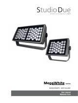 STUDIO DUE MEGAWHITE 66 M DALI Manuale utente
-
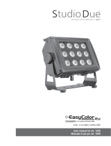 STUDIO DUE Easy Color 12.P Manuale utente
-
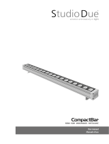 STUDIO DUE COMPACTBAR RGBW 100cm Manuale utente
-
 STUDIO DUE T-COLOR 6C RGBWA+UV Manuale utente
-
 STUDIO DUE SLIMBAR PLUS POB W 100 cm Manuale utente
-
 STUDIO DUE nanoLED User's And Operator's Manual
-
 STUDIO DUE CLEVER SPOT RGBW Manuale utente
-
 STUDIO DUE ARCHIBAR-SL100 RGBW/FC Manuale utente
-
 STUDIO DUE PARLED 300 PRO RGBW IP20 Manuale utente


Altri documenti
-
Griven Parade L3 Recessed Dynamic White Manuale del proprietario
-
-
-
-
Griven Moon wall Dynamic White Manuale del proprietario
-
iGuzzini BL41 Guida d'installazione
-
-
HELVAR 322 Guida d'installazione
-
 Thorn EP 445 / EP445 24L70-740 ND-A BPS CL2 MSU Guida d'installazione
-
HELVAR 320BD2 PIR Sensor Guida d'installazione
