
RVM 4280
Betriebsanleitung
Operating Instructions
Mode d'emploi
Manuale di istruzioni
Modo de empleo
取扱説明書
조작 설명서
操作手冊
使用说明
08/2023
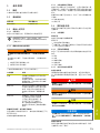
Betriebsanleitung........................................................................................................................................5
Operating Instructions............................................................................................................................ 14
Mode d'emploi.......................................................................................................................................... 23
Manuale di istruzioni...............................................................................................................................34
Modo de empleo......................................................................................................................................44
取扱説明書.................................................................................................. 55
조작 설명서............................................................................................................................................................64
操作手冊..........................................................................................................................................................73
使用说明................................................................................................................................................... 81
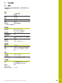
2

A
214
190
A
190
±
0.5
191
S
1.0 R
B
M30x0.5
7.5
183
15.5 (2x)
70
144
±
0.5
2
±
0.5
155
C
S
R
SW19
9
> 25
11.6
67.7
A
129.5
51.6
±
0.5
61.5
68
0.04 A
0.02 Y-Z
M12
R
0.2
0.4 R
0.05 R
D
Y
Z
X
Rx
Rz
Ry
3 4

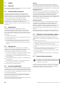
1 Grundlegendes
1.1 Überblick
Dieses Kapitel beinhaltet Informationen über das
vorliegende Produkt und die vorliegende Anleitung.
1.2 Informationen zum Produkt
Produktbezeichnung Identnummer (ID)
RVM 4280 1348763-01
1.3 Dokumentation zum Produkt
1.3.1 Gültigkeit der Dokumentation
Vor Gebrauch der Dokumentation und des Geräts
müssen Sie überprüfen, ob Dokumentation und Gerät
übereinstimmen.
Wenn die Identnummern nicht übereinstimmen
und die Dokumentation somit nicht gültig ist,
finden Sie die aktuelle Dokumentation unter
www.heidenhain.com.
1.3.2 Hinweise zum Lesen der Dokumentation
WARNUNG
Unfälle mit tödlichem Ausgang, Verletzungen oder
Sachschäden bei Nichtbeachtung der Dokumentation!
Wenn Sie die Dokumentation nicht beachten, können
Unfälle mit tödlichem Ausgang, Verletzungen von
Personen oder Sachschäden entstehen.
Dokumentation sorgfältig und vollständig lesen
Dokumentation aufbewahren zum Nachschlagen
Die folgende Tabelle enthält die Bestandteile der
Dokumentation in der Reihenfolge ihrer Priorität beim
Lesen.
Dokumentation Beschreibung
Addendum Ein Addendum ergänzt oder ersetzt
die entsprechenden Inhalte der
Betriebsanleitung und des Benut-
zerhandbuchs.
Ist ein Addendum im Lieferumfang
enthalten, hat es die höchste Priori-
tät beim Lesen. Alle übrigen Inhal-
te der Dokumentation behalten ihre
Gültigkeit.
Betriebsanleitung Die Betriebsanleitung enthält alle
Informationen und Sicherheitshin-
weise, um das Gerät sachgerecht
zu montieren und zu installieren.
Die Betriebsanleitung ist im Liefer-
umfang enthalten.
Die Betriebsanleitung hat die zweit-
höchste Priorität beim Lesen.
Benutzerhandbuch Das Benutzerhandbuch enthält
alle Informationen und Sicherheits-
hinweise, um das Gerät sachge-
recht und bestimmungsgemäß
zu betreiben. Das Benutzerhand-
buch kann im Downloadbereich von
www.heidenhain.de heruntergela-
den werden.
Das Benutzerhandbuch hat die dritt-
höchste Priorität beim Lesen.
Änderungen gewünscht oder den Fehlerteufel entdeckt?
Wir sind ständig bemüht, unsere Dokumentation für Sie zu
verbessern. Helfen Sie uns dabei und teilen uns bitte Ihre
Änderungswünsche unter folgender E-Mail-Adresse mit:
de
HEIDENHAIN | RVM 4280 | Operating Instructions | 08/2023 5

de
1.3.3 Aufbewahrung und Weitergabe der
Dokumentation
Die Anleitung muss in unmittelbarer Nähe des
Arbeitsplatzes aufbewahrt werden und dem gesamten
Personal jederzeit zur Verfügung stehen. Der Betreiber
muss das Personal über den Aufbewahrungsort dieser
Anleitung informieren. Wenn die Anleitung unleserlich
geworden ist, dann muss durch den Betreiber Ersatz beim
Hersteller beschafft werden.
Bei Übergabe oder Weiterverkauf des Geräts an Dritte
müssen die folgenden Dokumente an den neuen Besitzer
weitergegeben werden:
Addendum (falls mitgeliefert)
Betriebsanleitung
1.4 Zu dieser Anleitung
Diese Anleitung enthält alle Informationen und
Sicherheitshinweise, um das Gerät sachgerecht zu
betreiben.
1.4.1 Dokumententyp
Betriebsanleitung
Die vorliegende Anleitung ist die Betriebsanleitung des
Produkts.
Die Betriebsanleitung
ist am Produktlebenszyklus orientiert
enthält alle notwendigen Informationen und Sicherheits-
hinweise, um das Produkt sachgerecht und bestim-
mungsgemäß zu montieren und zu installieren
1.4.2 Zielgruppen der Anleitung
Die vorliegende Anleitung muss von jeder Person gelesen
und beachtet werden, die mit einer der folgenden Arbeiten
betraut ist:
Montage
Installation
Service und Wartung
Störungsbehebung
Demontage und Entsorgung
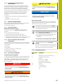
1.4.3 Verwendete Hinweise
Sicherheitshinweise
Sicherheitshinweise warnen vor Gefahren im Umgang mit
dem Gerät und geben Hinweise zu deren Vermeidung.
Sicherheitshinweise sind nach der Schwere der Gefahr
klassifiziert und in die folgenden Gruppen unterteilt:
GEFAHR
Gefahr signalisiert Gefährdungen für Personen. Wenn
Sie die Anleitung zum Vermeiden der Gefährdung nicht
befolgen, dann führt die Gefährdung sicher zum Tod
oder schweren Körperverletzungen.
WARNUNG
Warnung signalisiert Gefährdungen für Personen. Wenn
Sie die Anleitung zum Vermeiden der Gefährdung nicht
befolgen, dann führt die Gefährdung voraussichtlich
zum Tod oder schweren Körperverletzungen.
VORSICHT
Vorsicht signalisiert Gefährdungen für Personen. Wenn
Sie die Anleitung zum Vermeiden der Gefährdung nicht
befolgen, dann führt die Gefährdung voraussichtlich zu
leichten Körperverletzungen.
HINWEIS
Hinweis signalisiert Gefährdungen für Gegenstände
oder Daten. Wenn Sie die Anleitung zum Vermeiden der
Gefährdung nicht befolgen, dann führt die Gefährdung
voraussichtlich zu einem Sachschaden.
Informationshinweise
Informationshinweise gewährleisten einen fehlerfreien und
effizienten Einsatz des Geräts. Informationshinweise sind
in die folgenden Gruppen unterteilt:
Das Informationssymbol steht für einen Tipp.
Ein Tipp gibt wichtige zusätzliche oder
ergänzende Informationen.
Das Zahnradsymbol steht für eine
maschinenabhängige Funktion.
Die beschriebene Funktion ist
maschinenabhängig wenn, z.B.:
Ihre Maschine über eine notwendige
Software- oder Hardwareoption verfügt
Das Verhalten der Funktionen von konfigu-
rierbaren Einstellungen der Maschine abhängt
Das Buchsymbol steht für einen Querverweis.
Ein Querverweis führt zu externer
Dokumentation, z. B. der Dokumentation Ihres
Maschinenherstellers oder eines Drittanbieters.
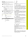
1.4.4 Textauszeichnungen
Darstellung Bedeutung
...
...
kennzeichnet einen Handlungsschritt und
das Ergebnis einer Handlung
Beispiel:
Auf OK tippen
Die Meldung wird geschlossen.
...
...
kennzeichnet eine Aufzählung
Beispiel:
Schnittstelle TTL
Schnittstelle EnDat
...
6HEIDENHAIN | RVM 4280 | Operating Instructions | 08/2023

2 Sicherheit
2.1 Überblick
Dieses Kapitel beinhaltet wichtige Informationen zur
Sicherheit, um das Gerät ordnungsgemäß zu betreiben.
2.2 Allgemeine Sicherheitsvorkehrungen
Für den Betrieb des Systems gelten die allgemein
anerkannten Sicherheitsvorkehrungen wie sie insbesondere
beim Umgang mit stromführenden Geräten erforderlich
sind. Nichtbeachtung dieser Sicherheitsvorkehrungen kann
Schäden am Gerät oder Verletzungen zur Folge haben.
Die Sicherheitsvorschriften können je nach Unternehmen
variieren. Im Falle eines Konflikts zwischen dem Inhalt
dieser Anleitung und den internen Regelungen eines
Unternehmens, in dem dieses Gerät verwendet wird, gelten
die strengeren Regelungen.
2.3 Bestimmungsgemäße Verwendung
Das Messgerät RVM 4280 dient zur hochpräzisen Messung
von Rund- und Schwenkachsen. Das Gerät wird dazu
temporär in Werkzeugmaschinen und auf Rundtischen
aufgebaut. Die Messdatenerfassung erfolgt über eine
EIB 74x und die PC-Software ACCOM 4.0.
Die Geräte dieser Baureihe
dürfen nur in gewerblichen Anwendungen und im indus-
triellen Umfeld eingesetzt werden
sind für die Verwendung in Innenräumen und in einer
Umgebung vorgesehen, in der die Belastung durch
Feuchtigkeit, Schmutz, Öl und Schmiermitteln den
Vorgaben in den technischen Daten entspricht
2.4 Bestimmungswidrige Verwendung
Jede Verwendung, die nicht in 'Bestimmungsgemäße
Verwendung' genannt ist, gilt als bestimmungswidrig. Für
hieraus resultierende Schäden haftet allein der Betreiber
des Geräts.
Unzulässig sind insbesondere folgende Verwendungen:
Verwendung mit defekten oder nicht normgerechten
Teilen, Kabeln oder Anschlüssen
Verwendung im Freien oder in explosions- oder feuerge-
fährlicher Umgebung
Verwendung außerhalb der Betriebsbedingungen
gemäß "Technische Daten"
Veränderungen am Gerät oder an der Peripherie ohne
Zustimmung der Hersteller
Einsatz als Bestandteil einer Sicherheitsfunktion
2.5 Qualifikation des Personals
Das Personal für Montage, Installation, Bedienung, Service,
Wartung und Demontage muss die entsprechende
Qualifikation für diese Arbeiten aufweisen und sich
mit Hilfe der Dokumentation des Geräts und der
angeschlossenen Peripherie ausreichend informiert haben.
Die Personalanforderungen, die für die einzelnen
Tätigkeiten am Gerät notwendig sind, sind in den
entsprechenden Kapiteln dieser Anleitung angegeben.
Nachfolgend sind die Personengruppen hinsichtlich ihrer
Qualifikationen und Aufgaben näher spezifiziert.
Bediener
Der Bediener nutzt und bedient das Gerät im Rahmen der
bestimmungsgemäßen Verwendung. Er wird vom Betreiber
über die speziellen Aufgaben und die daraus möglichen
Gefahren bei unsachgemäßem Verhalten unterrichtet.
Fachpersonal
Das Fachpersonal wird vom Betreiber in der erweiterten
Bedienung und Parametrierung ausgebildet. Das
Fachpersonal ist aufgrund seiner fachlichen Ausbildung,
Kenntnisse und Erfahrung sowie Kenntnis der
einschlägigen Bestimmungen in der Lage, die ihm
übertragenen Arbeiten hinsichtlich der jeweiligen
Applikation auszuführen und mögliche Gefahren
selbstständig zu erkennen und zu vermeiden.
Elektrofachkraft
Die Elektrofachkraft ist aufgrund ihrer fachlichen
Ausbildung, Kenntnisse und Erfahrungen sowie Kenntnis
der einschlägigen Normen und Bestimmungen in der
Lage, Arbeiten an elektrischen Anlagen auszuführen
und mögliche Gefahren selbstständig zu erkennen und
zu vermeiden. Die Elektrofachkraft ist speziell für das
Arbeitsumfeld ausgebildet, in dem sie tätig ist.
Die Elektrofachkraft muss die Bestimmungen der
geltenden gesetzlichen Vorschriften zur Unfallverhütung
erfüllen.
2.6 Betreiberpflichten
Der Betreiber besitzt das Gerät und die Peripherie
oder hat beides gemietet. Er ist jederzeit für die
bestimmungsgemäße Verwendung verantwortlich.
Der Betreiber muss:
die verschiedenen Aufgaben am Gerät qualifiziertem,
geeignetem und autorisiertem Personal zuweisen
das Personal nachweisbar in die Befugnisse und
Aufgaben unterweisen
sämtliche Mittel zur Verfügung stellen, die das Personal
benötigt, um die ihm zugewiesenen Aufgaben zu
erfüllen
sicherstellen, dass das Gerät ausschließlich in
technisch einwandfreiem Zustand betrieben wird
sicherstellen, dass das Gerät gegen unbefugte
Benutzung geschützt wird
2.7 Allgemeine Sicherheitshinweise
Die Verantwortung für jedes System, in dem
dieses Produkt verwendet wird, liegt bei dem
Monteur oder Installateur dieses Systems.
Die spezifischen Sicherheitshinweise, die für die einzelnen
Tätigkeiten am Gerät zu beachten sind, sind in den
entsprechenden Kapiteln dieser Anleitung angegeben.
de
HEIDENHAIN | RVM 4280 | Operating Instructions | 08/2023 7

de
2.7.1 Sicherheitshinweise zur Elektrik
WARNUNG
Gefahr von gefährlicher Körperdurchströmung
bei direktem oder indirektem Kontakt mit
spannungsführenden Teilen.
Elektrischer Schock, Verbrennungen oder der Tod
können die Folge sein.
Arbeiten an der Elektrik und an stromführenden
Bauteilen nur durch eine ausgebildete Fachkraft
durchführen lassen
Für Netzanschluss und alle Schnittstellenanschlüsse
ausschließlich normgerecht gefertigte Kabel und
Stecker verwenden
Defekte elektrische Bauteile sofort über den
Hersteller austauschen lassen
Alle angeschlossenen Kabel und Anschlussbuchsen
des Geräts regelmäßig prüfen. Mängel, z. B. lose
Verbindungen bzw. angeschmorte Kabel, sofort
beseitigen
HINWEIS
Beschädigung innerer Gerätebauteile!
Wenn Sie die Schraubverbindungen des Geräts öffnen,
erlöschen die Gewährleistung und die Garantie.
Auf keinen Fall die Schraubverbindungen öffnen
Eingriffe nur vom Gerätehersteller vornehmen lassen
2.8 Spezifische Sicherheitshinweise
WARNUNG
Im Messbetrieb können sich ggf. Geräteteile lösen
Quetsch- und Stoßgefahr durch herumfliegende
Geräteteile
Vorhandene Türen oder Abdeckungen schließen
HINWEIS
Beschädigung von Abtastkopf und Teilungstrommel
Oberfläche des Sensors am Abtastkopf nicht
berühren
Teilung der Teilungstrommel nicht berühren
Stoßbelastung auf Abtastmodul und Teilung der
Teilungstrommel vermeiden
3 Transport und Lagerung
3.1 Überblick
Dieses Kapitel beinhaltet Informationen zu Transport und
Lagerung sowie zu Lieferumfang und Zubehör des Geräts.
Die nachfolgenden Schritte dürfen nur von
Fachpersonal durchgeführt werden.
Weitere Informationen: "Qualifikation des
Personals", Seite 7
3.2 Gerät auspacken
Verpackungskarton oben öffnen
Verpackungsmaterial entfernen
Inhalt entnehmen
Lieferung auf Vollständigkeit prüfen
Lieferung auf Transportschäden kontrollieren
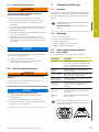
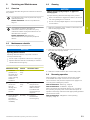
3.3 Lieferumfang und Zubehör
3.3.1 Lieferumfang
In der Lieferung sind folgende Artikel enthalten:
Bezeichnung Beschreibung
Gerät Messgerät RVM 4280 bestehend aus
Teilungstrommel und Abtastmodul mit
Messleitungen mit gekennzeichneten
Steckern zur Verbindung mit EIB 74x
Aufnahmeadap-
ter
Verbindungsteil zwischen Abtastmo-
dul und Werkzeugaufnahme
Zentrierstück Montagehilfe für die Ausrichtung der
Teilungstrommel am Einbauwinkel
Qualitätsprüfbe-
scheinigung
Bescheinigung über die Systemgenau-
igkeit des Messgeräts
Betriebsanlei-
tung
Gedruckte Ausgabe der Betriebsan-
leitung in den aktuell verfügbaren
Sprachen
Addendum
(optional)
Ergänzt oder ersetzt Inhalte der
Betriebsanleitung
Gerätekoffer Koffer für den gesamten Lieferumfang
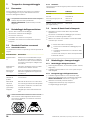
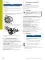
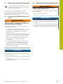
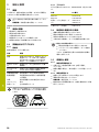
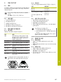
Überprüfen Sie anhand der Bezeichnung und
der Seriennummer auf dem Typenschild, dass
Teilungstrommel und Abtastmodul zueinander
gehören.
R
V
M
4
x
x
x
I
D
1
2
3
4
5
6
7
-
0
1
S
N
1
2
3
4
5
6
7
8
9
A
W
1
2
H
E
I
D
E
N
H
A
I
N
RVM 4280 HEIDENHAIN
www.heidenhain.de
ID 12345678-01
SN 123 456 789 A W12
8HEIDENHAIN | RVM 4280 | Operating Instructions | 08/2023

3.3.2 Zubehör
Das nachfolgend aufgeführte Zubehör kann bei
HEIDENHAIN bestellt werden:
Bezeichnung Identnummer
EIB 741 617574-02
EIB 742 1037960-02
Verlängerungskabel
(Messkabel)
354379-xx
355397-xx
Werkzeugaufnahme
(anwendungsspezifisch)
620174-xx
3.4 Wenn ein Transportschaden vorliegt
Schaden vom Spediteur bestätigen lassen
Verpackungsmaterialien zur Untersuchung aufheben
Absender über den Schaden benachrichtigen
Händler oder Maschinenhersteller bezüglich
Ersatzteilen kontaktieren
Bei einem Transportschaden:
Die Verpackungsmaterialien zur
Untersuchung aufbewahren
HEIDENHAIN oder Maschinenhersteller
kontaktieren
Dies gilt auch für Transportschäden an
Ersatzteilanforderungen.
3.5 Wiederverpackung und Lagerung
3.5.1 Gerät wieder verpacken
Gerät ggf. reinigen (siehe "Reinigung", Seite 12)
Gerät umsichtig verpacken und immer im Gerätekoffer
lagern
3.5.2 Gerät lagern
Gerät wie vorher beschrieben verpacken
Bestimmungen für die Umgebungsbedingungen
beachten
Weitere Informationen: "Technische Daten",
Seite 13
Gerät nach jedem Transport und nach längerer
Lagerung auf Beschädigungen prüfen
4 Montage
4.1 Überblick
Dieses Kapitel beschreibt die Montagedes Geräts.
Die nachfolgenden Schritte dürfen nur von
Fachpersonal durchgeführt werden.
Weitere Informationen: "Qualifikation des
Personals", Seite 7
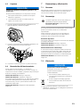
4.2 Anbau des Geräts
WARNUNG
Quetsch- und Stoßgefahr durch bewegliche Teile
Bei Montagearbeiten im Inneren von
Werkzeugmaschinen kann es zu Quetschungen oder
Stößen durch bewegliche Teile kommen.
Werkzeugmaschine vor dem Einbau des Geräts in
den Einrichtbetrieb schalten
Alle beweglichen Teile sichern
Schutzausrüstung tragen
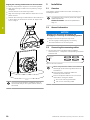
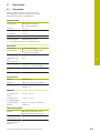
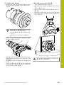
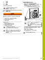
Der Anbau des RVM 4280 umfasst folgende
Arbeitsschritte:
1 Teilungstrommel mit Anbauwinkel auf Bearbei-
tungstisch montieren
2 Abtastmodul in Werkzeugspindel montieren
3 Abtastmodul zur Teilungstrommel ausrichten
Die Montageflächen müssen gratfrei und
sauber sein
Den direkten Kontakt von Flüssigkeiten mit
Messgerät und Steckverbinder vermeiden
Die Montage des RVM 4280 erfordert den Einsatz
eines maschinenspezifischen Anbauwinkels.
Dieser Anbauwinkel muss vom Kunden gemäß
den Angaben in der Anschlussmaßzeichnung
selbst hergestellt werden.
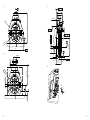
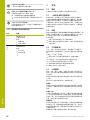
Weitere Informationen: "C", Seite 4
de
HEIDENHAIN | RVM 4280 | Operating Instructions | 08/2023 9

de
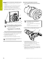
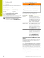
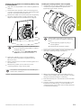
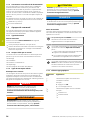
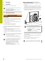
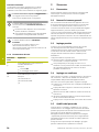
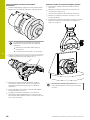
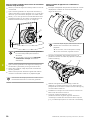
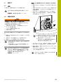
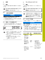
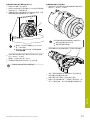
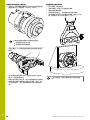
Teilungstrommel mit Anbauwinkel auf Bearbeitungstisch
montieren
Anbauwinkel auf Bearbeitungstisch ausrichten und
montieren
Teilungstrommel mit dem Zentrierstück (1) auf dem
Anbauwinkel befestigen, mit 30Nm Drehmoment
festziehen, dann eine halbe Umdrehung lösen
Rundlauf der Teilungstrommel durch Antasten mit
Messuhren am äußeren Zentrierbund (2) messen und
ggf. einstellen (siehe "A", Seite 4)
A
0.4 A
2
±
0.5
Die Teilungstrommel zu Beginn möglichst
weit nach oben schieben, um das
Ausrichten zu erleichtern
Wenn möglich, die Funktion RVM 4280
Anbauassistent der Software ACCOM 4.0
nutzen
Teilungstrommel auf dem Anbauwinkel mit Schrauben
M12 und Scheiben befestigen, Drehmoment 84 ± 5Nm
Vor der Messung das Zentrierstück aus der
Teilungstrommel entfernen
Position der Teilungstrommel auf dem
Bearbeitungstisch mit einem Tastsystem ermitteln
Die positive Zählrichtung ist als Richtungspfeil
auf der Teilungstrommel sichtbar.
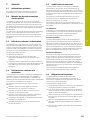
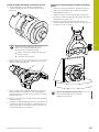
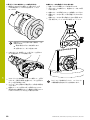
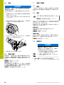
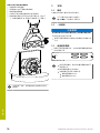
Abtastmodul in Werkzeugspindel montieren
Aufnahmeadapter über das Feingewinde M30x0.5
mit dem Abtastmodul verschrauben, Drehmoment
80 ± 5Nm
Zum Aufbringen des Drehmoments die
Schlüsselweite an der Unterseite des
Abtastmoduls nutzen.
Zum Gegenhalten einen Montageblock
nutzen
Ggf. das Gewinde nachschmieren
Aufnahmeadapter und Werkzeugaufnahme über vier
Schrauben (1) mit dem Abtastmodul verbinden
Gesamtlänge des Anbaus (Abtastmodul
und Werkzeugaufnahme) mit einem
Werkzeugvoreinstellgerät vermessen, dabei das
Langloch (2) als Bezugskante verwenden
Anbau als Handwerkzeug in der Tool-Tabelle der
Steuerung anlegen
Abtastmodul mit Werkzeugaufnahme verdrehsicher
(elektrische oder mechanische Klemmung) auf der
Werkzeugseite der Maschine (z.B. Spindel bei einem
Bearbeitungszentrum) einsetzen
10 HEIDENHAIN | RVM 4280 | Operating Instructions | 08/2023

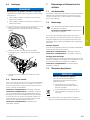
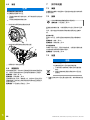
Abtastmodul zur Teilungstrommel ausrichten
Schutzkappen der Abtastköpfe entfernen
Abtastmodul mit Hilfe einer Messuhr in der Y-Z-Ebene
ausrichten
Verdrehsicherheit des Abtastmoduls sicherstellen
Abtastmodul in X- und Y-Ebene zur Teilungstrommel
ausrichten
Abtastmodul in Z-Ebene zur Teilungstrommel
positionieren, Maße siehe "B", Seite 4 und siehe "C",
Seite 4
0.02 Y -
Z
Nach Abschluss der Einrichtarbeiten wird
empfohlen, die Verfahrgrenzen in der Steuerung
einzurichten.
5 Installation
5.1 Überblick
Dieses Kapitel beinhaltet alle Informationen zur Installation
des Geräts.
Die nachfolgenden Schritte dürfen nur von
Fachpersonal durchgeführt werden.
Weitere Informationen: "Qualifikation des
Personals", Seite 7
5.2 Allgemeine Hinweise
HINWEIS
Geräteschaden durch Herstellen und Lösen von
Steckverbindungen während des Betriebs!
Interne Bauteile können beschädigt werden.
Steckverbindungen nur bei ausgeschaltetem Gerät
herstellen oder lösen
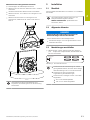
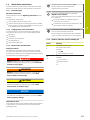
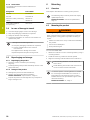
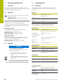
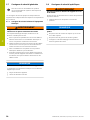
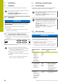
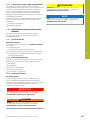
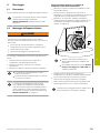
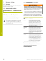
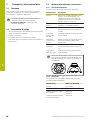
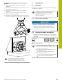
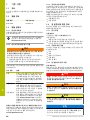
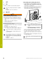
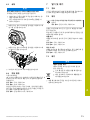
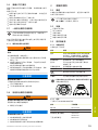
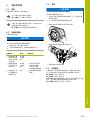
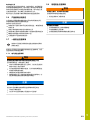
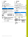
5.3 Messleitungen anschließen
Messleitungen mit den gekennzeichneten Steckern
(X11 ... X13) an die entsprechenden Schnittstellen der
EIB 74x anschließen
X12 X 14
X 11 X13
HEIDENHAIN
STAT US
LAN
POWER
Abbildung 1: Schnittstellen EIB 74x
Achten Sie bei der Verwendung von Verlän-
gerungskabeln darauf, dass die Gesamtlänge
aller Messleitungen 20m nicht überschreitet
Achten Sie auf eine ausreichende
Zugentlastung der Messleitungen
Achten Sie beim Verlegen auf den minimalen
Biegeradius:
40mm für Abtastkopfkabel
100mm für Verbindungskabel
de
HEIDENHAIN | RVM 4280 | Operating Instructions | 08/2023 11

de
6 Service und Wartung
6.1 Überblick
Dieses Kapitel beschreibt die allgemeinen
Wartungsarbeiten am Gerät.
Die nachfolgenden Schritte dürfen nur von
Fachpersonal durchgeführt werden.
Weitere Informationen: "Qualifikation des
Personals", Seite 7
Dieses Kapitel enthält nur die Beschreibung
der Wartungsarbeiten am Gerät. Anfallende
Wartungsarbeiten an Peripheriegeräten werden in
diesem Kapitel nicht beschrieben.
Weitere Informationen: Herstellerdokumentation
der betreffenden Peripheriegeräte
6.2 Wartungsplan
Das Gerät arbeitet weitgehend wartungsfrei.
HINWEIS
Betrieb defekter Geräte
Der Betrieb defekter Geräte kann zu schweren
Folgeschäden führen.
Gerät bei Beschädigung nicht reparieren und nicht
mehr betreiben
Defekte Geräte sofort austauschen oder eine
HEIDENHAIN-Serviceniederlassung kontaktieren
Wartungsschritt Intervall Fehlerbehebung
Teilung der
Teilungstrom-
mel sowie
Strichplatte
der Abtastköp-
fe auf Kratzer
prüfen
vor jeder
Verwen-
dung
Elektrische
Verbindungen
auf Beschä-
digungen
und Funktion
prüfen
vor jeder
Verwen-
dung
Fehlerhafte Leitun-
gen durch Fachper-
sonal austau-
schen. Bei Bedarf
HEIDENHAIN-
Serviceniederlas-
sung kontaktieren
Alle Kennzeich-
nungen,
Beschriftungen
und Symbole
auf dem Gerät
auf Lesbarkeit
prüfen
jährlich HEIDENHAIN-
Serviceniederlas-
sung kontaktieren
6.3 Reinigung
HINWEIS
Reinigung mit scharfkantigen oder aggressiven
Reinigungsmitteln
Das Gerät wird durch falsche Reinigung beschädigt.
Keine scheuernden oder aggressiven
Reinigungsmittel oder Lösungsmittel verwenden
Hartnäckige Verschmutzungen nicht mit
scharfkantigen Gegenständen entfernen
Teilung der Teilungstrommel mit einem fusselfreien
Tuch und Isopropylalkohol reinigen
Vorderseite der Abtastköpfe mit einem fusselfreien
Tuch und Isopropylalkohol reinigen
Außenflächen mit weichem Tuch trocken reinigen
6.4 Wiederaufnahme des Betriebs
Bei der Wiederaufnahme des Betriebs, z.B. bei der
Reinstallation im Anschluss an eine Reparatur oder nach
Wiedermontage, sind am Gerät die gleichen Maßnahmen
und Personalanforderungen erforderlich wie bei der
Montage und Installation.
Weitere Informationen: "Montage", Seite 9
Weitere Informationen: "Installation", Seite 11
Der Betreiber muss beim Anschließen der Peripheriegeräte
(z.B. Messgeräte) für die sichere Wiederaufnahme
des Betriebs sorgen und autorisiertes Personal mit
entsprechender Qualifikation einsetzen.
Weitere Informationen: "Betreiberpflichten", Seite 7
12 HEIDENHAIN | RVM 4280 | Operating Instructions | 08/2023

7 Demontage und Entsorgung
7.1 Überblick
Dieses Kapitel beinhaltet Hinweise und
umweltschutzrechtliche Vorgaben, die Sie für eine korrekte
Demontage und Entsorgung des Geräts beachten müssen.
7.2 Demontage
Die nachfolgenden Schritte dürfen nur von
Fachpersonal durchgeführt werden.
Weitere Informationen: "Qualifikation des
Personals", Seite 7
Abhängig von der angeschlossenen Peripherie kann für die
Demontage eine Elektrofachkraft erforderlich sein.
Ebenfalls zu beachten sind die entsprechenden
Sicherheitshinweise, die bei der Installation der
betreffenden Komponenten angegeben sind.
Gerät abbauen
Demontieren Sie das Gerät in umgekehrter Installations-
und Montagereihenfolge.
Weitere Informationen: "Montage", Seite 9
Weitere Informationen: "Installation", Seite 11
Lagerung nach der Demontage
Wenn das Gerät nach der Demontage zwischengelagert
wird, müssen Sie die Hinweise zur Wiederverpackung
beachten und die Bestimmungen für die
Umgebungsbedingungen einhalten.
Weitere Informationen: "Technische Daten", Seite 13
7.3 Entsorgung
HINWEIS
Falsche Entsorgung des Geräts!
Wenn Sie das Gerät falsch entsorgen,
können Umweltschäden die Folge sein.
Elektroschrott und Elektronikkomponen-
ten nicht im Hausmüll entsorgen
Gerät gemäß den örtlichen Entsorgungs-
vorschriften der Wiederverwertung zufüh-
ren
Bei Fragen zur Entsorgung des Geräts eine
HEIDENHAIN-Serviceniederlassung kontaktieren
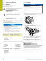
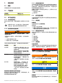
8 Technische Daten
8.1 Überblick
Dieses Kapitel beinhaltet eine Übersicht der Gerätedaten
und Zeichnungen mit den Geräte- und Anschlussmaßen.
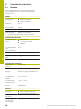
Gerät
Komponenten Abtastmodul
Teilungstrommel
Durchmesser 1) 191mm
Höhe 1) 67,7mm
Tiefe 1) 214mm
Masse 5,5kg
Befestigungsart Montage mit 2 Schrauben
1) ohne Werkzeugaufnahme, im Messbetrieb
Elektrische Daten
Versorgungsspan-
nung
DC 5V ± 0,5V
< 100 mA (je Abtastkopf)
Ausgangskabel 3x Ø 3,7 mm x 2,8 m
Kabellänge max.
(inkl. Verlänge-
rung)
20 m
Schnittstelle 3x Stecker Sub-D, 15-polig, Stift, mit
Verriegelungsschrauben
Inkrementalsignale ~1 Vss
Messschritt ≥ 0,03" (mit EIB 74x)
Mechanische Daten
Drehzahl ≤ 100 U/min
Vibration ≤ 80 m/s2 (gemäß EN 60068-2-6)
Schock ≤ 200 m/s2 (gemäß EN 60068-2-27)
Umgebung
Arbeitstemperatur +15 °C ... +25 °C
Lagertemperatur –20 °C ... +70 °C
Relative Luftfeuch-
tigkeit
≤ 93 % r.H. nicht kondensierend
Allgemein
Richtlinien EMV-Richtlinie 2014/30/EU
RoHS-Richtlinie 2011/65/EU
Schutzart
EN 60529
IP 00
Gesamtgewicht
des Lieferumfangs
11,1kg
de
HEIDENHAIN | RVM 4280 | Operating Instructions | 08/2023 13

en
1 Fundamentals
1.1 Overview
This chapter contains information about the product and
this manual.
1.2 Product information
Product designation Part number (ID)
RVM 4280 1348763-01
1.3 Documentation on the product
1.3.1 Validity of the documentation
Before using the documentation and the product, you need
to verify that the documentation matches the product.
If the ID numbers do not match so that the
documentation is not valid, you will find the
current documentation at www.heidenhain.com.
1.3.2 Notes on reading the documentation
WARNING
Fatal accidents, personal injury or property damage
caused by non-compliance with the documentation!
Failure to comply with the documentation may result in
fatal accidents, personal injury or property damage.
Read the documentation carefully from beginning to
end
Keep the documentation for future reference
The following table lists the various parts of the
documentation in their order of reading priority.
Document type Description
Addendum An Addendum supplements or
supersedes the relevant contents of
the Operating Instructions and the
User's Manual.
If an Addendum is included in deliv-
ery, then it has the highest reading
priority. All other documentation
content retains its validity.
Operating Instruc-
tions
The Operating Instructions contain
all the information and safety
precautions needed for the proper
mounting and installation of the
product. The Operating Instructions
are included in delivery.
The Operating Instructions have the
second highest priority for reading.
User's Manual The User's Manual contains all the
information and safety precautions
needed for the proper operation of
the product according to its intend-
ed use. The User's Manual can be
downloaded from the download
area at www.heidenhain.com.
The User's Manual has the third
highest priority for reading.
Have you found any errors or would you like to suggest
changes?
We continuously strive to improve our documentation for
you. Please help us by sending your suggestions to the
following e-mail address:
1.3.3 Storage and distribution of the documentation
The instructions must be kept in the immediate vicinity of
the workplace and must be available to all personnel at all
times. The operating company must inform the personnel
where these instructions are kept. If the instructions have
become illegible, the operating company must obtain a new
copy from the manufacturer.
If the product is given or resold to any other party, the
following documents must be passed on to the new owner:
Addendum (if supplied)
Operating Instructions
14 HEIDENHAIN | RVM 4280 | Operating Instructions | 08/2023

1.4 About these instructions
These instructions provide all the information and safety
precautions needed for the safe operation of the device.
1.4.1 Document type
Operating Instructions
These instructions are the Operating Instructions for the
product.
The Operating Instructions
are oriented to the product life cycle
contain all information and safety precautions needed
for the proper mounting and installation of the product
in accordance with its intended use
1.4.2 Target groups of the instructions
These instructions must be read and complied with by
every person who performs any of the following tasks:
Mounting
Installation
Service and maintenance
Troubleshooting
Removal and disposal
1.4.3 Notes in this documentation
Safety precautions
Precautionary statements warn of hazards in handling
the product and provide information on their prevention.
Precautionary statements are classified by hazard severity
and divided into the following groups:
DANGER
Danger indicates hazards for persons. If you do not
follow the avoidance instructions, the hazard will result
in death or severe injury.
WARNING
Warning indicates hazards for persons. If you do not
follow the avoidance instructions, the hazard could
result in death or serious injury.
CAUTION
Caution indicates hazards for persons. If you do not
follow the avoidance instructions, the hazard could
result in minor or moderate injury.
NOTICE
Notice indicates danger to material or data. If you do
not follow the avoidance instructions, the hazard could
result in property damage.
Informational notes
Informational notes ensure reliable and efficient operation
of the product. Informational notes are divided into the
following groups:
The information symbol indicates a tip.
A tip provides important additional or
supplementary information.
The gear symbol indicates a function that
depends on the machine.
The function described depends on the machine
if, for example:
A certain software or hardware option is
required on your machine
The behavior of the functions depends on the
configurable machine settings
The book symbol indicates a cross reference.
A cross reference leads to external
documentation for example the documentation
of your machine manufacturer or other supplier.
1.4.4 Symbols and fonts used for marking text
Format Meaning
...
...
Identifies an action and
the result of this action
Example:
Tap OK
The message is closed
...
...
Identifies an item of a list
Example:
TTL interface
EnDat interface
...
en
HEIDENHAIN | RVM 4280 | Operating Instructions | 08/2023 15

en
2 Safety
2.1 Overview
This chapter provides important safety information needed
for the proper operation of the unit.
2.2 General safety precautions
General accepted safety precautions, in particular the
applicable precautions relating to the handling of live
electrical equipment, must be followed when operating the
system. Failure to observe these safety precautions may
result in personal injury or damage to the device.
It is understood that safety rules within individual
companies vary. If a conflict exists between the material
contained in these instructions and the rules of a
company using this system, the more stringent rules take
precedence.
2.3 Intended use
The RVM 4280 encoder enables high-precision
measurement of rotary and tilting axes. This requires a
temporary installation of the encoder in machine tools
and on rotary tables. An EIB 74x external interface box and
the ACCOM 4.0 PC software are used for measured value
acquisition.
The products of this series
must be used only in commercial applications and in an
industrial environment
are intended for indoor use in an environment in which
the contamination caused by humidity, dirt, oil, and
lubricants complies with the requirements of the speci-
fications
2.4 Improper use
Any use not specified in 'Intended use' is considered
improper use. The company operating the device is solely
liable for any damage resulting from improper use.
In particular, the following uses are not permitted:
Use with parts, cables or connections that are defective
or do not comply with the applicable standards
Use outdoors, or in potentially explosive environments
or fire risk areas
Use outside the operating conditions as detailed under
"Specifications"
Any alterations of the device or peripherals that have
not been authorized by the manufacturers
Use as a part of a safety function
2.5 Personnel qualification
The personnel for mounting, installation, operation, service,
maintenance, and removal must be appropriately qualified
for this work and must have obtained sufficient information
from the documentation supplied with the product and with
the connected peripherals.
The personnel required for the individual activities to be
performed on the product are indicated in the respective
sections of these instructions.
The personnel groups are specified in detail as follows with
regard to their qualifications and tasks.
Operator
The operator uses and operates the product within the
framework specified for the intended use. The operator is
informed by the operating company about the special tasks
and the potential hazards resulting from incorrect behavior.
Qualified personnel
Qualified personnel are trained by the operating company
to perform advanced operation and parameterization. Due
to their specialized training, knowledge, and experience,
including their knowledge of the relevant regulations,
qualified personnel are able to perform their assigned tasks
with respect to the given application and to recognize and
avoid potential hazards on their own.
Electrical specialist
Due to their technical training, knowledge, and experience,
including their knowledge of the relevant standards and
regulations, electrical specialists are able to work on
electrical installations and to recognize and avoid potential
hazards on their own. Electrical specialists have been
trained specifically for the work environment in which they
operate.
Electrical specialists must comply with the provisions of
the applicable statutory regulations on accident prevention.
2.6 Obligations of the operating company
The operating company owns or leases the device and
the peripherals. At all times, the operating company is
responsible for ensuring that the intended use is complied
with.
The operating company must:
Assign the different tasks to be performed on the device
to suitable, qualified and authorized personnel
Verifiably train the personnel in the authorizations and
tasks
Provide all materials and means necessary in order for
the personnel to complete the assigned tasks
Ensure that the device is operated only when in perfect
technical condition
Ensure that the device is protected from unauthorized
use
2.7 General safety precautions
The safety of any system incorporating the use of
this product is the responsibility of the assembler
or installer of the system.
The specific safety precautions required for the individual
activities to be performed on the product are indicated in
the respective sections of these instructions.
16 HEIDENHAIN | RVM 4280 | Operating Instructions | 08/2023

2.7.1 Electrical safety precautions
WARNING
Hazard of dangerous amount of electricity passing
through the human body upon direct or indirect
contact with live electrical parts.
This may result in electric shock, burns or death.
Work on the electrical system and live electrical
components is to be performed only by trained
specialists
For power connection and all interface connections,
use only cables and connectors that comply with
applicable standards
Have the manufacturer exchange defective electrical
components immediately
Regularly inspect all connected cables and all
connections on the product. Defects, such as loose
connections or scorched cables, must be removed
immediately
NOTICE
Damage to internal parts of the product!
Opening the screw connections of the product will void
all warranties and guarantees.
Never open the screw connections
Only the product manufacturer is permitted to
access the inside of the product
2.8 Specific safety precautions
WARNING
Parts of the device may come off during measuring
operation
Crushing and impact hazards due to moving parts
Close any doors or covers
NOTICE
Damage to scanning head and scale drum
Do not touch the surface of the sensor on the
scanning head
Do not touch the graduation of the scale drum
Avoid impact load on the scanning module and the
graduation of the scale drum
3 Transport and Storage
3.1 Overview
This chapter contains information for the transportation
and storage of the product and provides an overview of
the items supplied and the available accessories of the
product.
The following steps must be performed only by
qualified personnel.
Further information: "Personnel qualification",
Page 16
3.2 Unpacking
Open the top of the box
Remove the packaging materials
Unpack the contents
Check the delivery for completeness
Check the delivery for damage
3.3 Items supplied and accessories
3.3.1 Items supplied
The following items are included in the shipment:
Designation Description
Product RVM 4280 encoder consisting of
scale drum and scanning module with
measuring cables with labeled connec-
tors for connection to the EIB 74x
Mounting
adapter
Adapter between scanning module
and tool holder
Centering piece Mounting aid for aligning the scale
drum on the mounting bracket
Quality Inspec-
tion Certificate
Certificate stating the system accura-
cy of the encoder
Operating
Instructions
Printed issue of the Operating Instruc-
tions in the currently available
languages
Addendum
(optional)
Supplements or supersedes the corre-
sponding contents of the Operating
Instructions
Equipment
case
Case for storing and transporting all
items supplied
Based on the designation and serial number on
the ID label, verify that the scale drum matches
the scanning module.
R
V
M
4
x
x
x
I
D
1
2
3
4
5
6
7
-
0
1
S
N
1
2
3
4
5
6
7
8
9
A
W
1
2
H
E
I
D
E
N
H
A
I
N
RVM 4280 HEIDENHAIN
www.heidenhain.de
ID 12345678-01
SN 123 456 789 A W12
en
HEIDENHAIN | RVM 4280 | Operating Instructions | 08/2023 17

en
3.3.2 Accessories
The following accessories can be ordered from
HEIDENHAIN:
Designation Part number
EIB 741 617574-02
EIB 742 1037960-02
Extension cable (measuring
cable)
354379-xx
355397-xx
Tool holder (applica-
tion-specific)
620174-xx
3.4 In case of damage in transit
Have the shipping agent confirm the damage
Keep the packaging materials for inspection
Notify the sender of the damage
Contact the distributor or machine manufacturer for
replacement parts
If damage occurred during transit:
Keep the packaging materials for inspection
Contact HEIDENHAIN or the machine
manufacturer
This applies also if damage occurred to
requested replacement parts during transit.
3.5 Repackaging and storage
3.5.1 Repackaging the product
Clean the product if needed (see "Cleaning",
Page 21)
Carefully package the product and always store it in the
equipment case
3.5.2 Storage of the product
Package the product as described above
Observe the specified ambient conditions
Further information: "Specifications", Page 22
Inspect the product for damage after any transport or
longer storage times
4 Mounting
4.1 Overview
This chapter describes the mounting of the product.
The following steps must be performed only by
qualified personnel.
Further information: "Personnel qualification",
Page 16
4.2 Mounting the product
WARNING
Crushing and impact hazards due to moving parts
When mounting work is performed inside a machine's
working space, moving parts may lead to crushing or
impact.
Switch the machine to set-up mode before installing
the product
Secure all movable parts
Wear protective gear
To mount the RVM 4280:
1 Attach the scale drum to the machining table by using a
mounting bracket
2 Install the scanning module in the tool spindle
3 Align the scanning module relative to the scale drum
The mounting surfaces must be clean and
free of burrs
Avoid allowing the encoder and connector to
come into direct contact with fluids
A machine-specific mounting bracket is needed
for mounting the RVM 4280. The customer is
responsible for manufacturing this mounting
bracket based on the specifications given in the
dimension drawing.
Further information: "C", Page 4
18 HEIDENHAIN | RVM 4280 | Operating Instructions | 08/2023

Attaching the scale drum to the machining table by using
a mounting bracket
Align the mounting bracket on the machining table and
attach it
Screw-fasten the scale drum with the centering piece
(1) to the mounting bracket by using a tightening torque
of 30Nm, and then loosen by half a turn
Measure the radial runout of the scale drum by probing
the outer centering collar (2) with a dial gauge, and
adjust the radial runout as needed (see "A", Page 4)
A
0.4 A
2
±
0.5
At the beginning, move the scale drum as
far up (Z+ direction) as possible, in order to
facilitate alignment
Preferably, use the RVM 4280 Mounting
wizard of the ACCOM 4.0 software
Fasten the scale drum to the mounting bracket
with M12 screws and washers (tightening torque:
84 Nm, ± 5Nm)
Before measurement, remove the centering piece from
the scale drum
Measure the position of the scale drum on the
machining table by using a touch probe
The positive counting direction is indicated by an
arrow on the scale drum.
Installing the scanning module in the tool spindle
Screw-fasten the mounting adapter to the scanning
module by using the M30x0.5 fine-pitch thread
(tightening torque: 80 Nm, ±5Nm)
Use the width across flats on the bottom of
the scanning module to apply the tightening
torque.
Provide opposing support by using a
mounting block
Relubricate the thread as needed
Fasten the mounting adapter and the tool holder to the
scanning module by using four screws (1)
Measure the total length of the assembly (scanning
module and tool holder) with a tool presetter, using the
slot (2) as a reference edge for measuring
Enter the assembly as a manual tool into the tool table
of the control
Insert the scanning module with the tool holder on the
tool side of the machine (e.g., into the spindle on a
machining center) such that it cannot rotate (electrical
or mechanical clamping)
en
HEIDENHAIN | RVM 4280 | Operating Instructions | 08/2023 19

en
Aligning the scanning module relative to the scale drum
Remove the protective caps from the scanning heads
Align the scanning module in the Y/Z plane by using a
dial gauge
Prevent rotation of the scanning module
Align the scanning module relative to scale drum in the
planes X and Y
Position the scanning module relative to the scale drum
in the Z plane; for dimensions, see see "B", Page 4 and
see "C", Page 4
0.02 Y -
Z
Once you have finished the installation work, we
recommend that you set up the traverse limits in
the control.
5 Installation
5.1 Overview
This chapter contains all the information necessary for
installing the device.
The following steps must be performed only by
qualified personnel.
Further information: "Personnel qualification",
Page 16
5.2 General information
NOTICE
Damage to the device from the engaging and
disengaging of connecting elements during operation!
Damage to internal components may result.
Do not engage or disengage any connecting
elements while the unit is under power
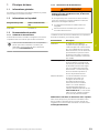
5.3 Connecting the measuring cables
Connect the measuring cables with the labeled
connectors (X11 ... X13) to the corresponding interfaces
of the EIB 74x
X12 X 14
X 11 X13
HEIDENHAIN
STAT US
LAN
POWER
Figure 2: EIB 74x interfaces
When using extension cables, ensure that the
total length of all measuring cables does not
exceed 20m
Ensure that the measuring cables are
sufficiently strain-relieved
Ensure compliance with the minimum bend
radius when routing the cables:
40mm for scanning head cable
100mm for connecting cable
20 HEIDENHAIN | RVM 4280 | Operating Instructions | 08/2023

6 Servicing and Maintenance
6.1 Overview
This chapter describes the general maintenance work on
the product.
The following steps must be performed only by
qualified personnel.
Further information: "Personnel qualification",
Page 16
This chapter contains a description of
maintenance work for the product only. Any
maintenance work on peripheral devices is not
described in this chapter.
Further information: Manufacturer's
documentation for the respective peripheral
devices
6.2 Maintenance schedule
The product is largely maintenance-free.
NOTICE
Operating defective devices
Operating defective devices may result in serious
consequential damage.
Do not repair or operate the device if it is damaged
Replace defective devices immediately or contact a
HEIDENHAIN service agency
Maintenance step Interval Corrective action
Check the
graduation of
the scale drum
and the reticle
of the scanning
heads for
scratches
Before
every
use
Inspect electri-
cal connec-
tions for
damage and
check their
function
Before
every
use
Have quali-
fied personnel
replace defective
cables. Contact
a HEIDENHAIN
service agency if
required
Check all labels
and symbols
provided on
the product for
readability
Annually Contact a
HEIDENHAIN
service agency
6.3 Cleaning
NOTICE
Cleaning with sharp-edged objects or aggressive
cleaning agents
Improper cleaning will cause damage to the product.
Never use abrasive or aggressive cleaners, and never
use strong detergents or solvents
Do not use sharp-edged objects to remove persistent
contamination
Clean the graduation of the scale drum with a lint-free
cloth and isopropyl alcohol
Clean the front face of the scanning heads with a lint-
free cloth and isopropyl alcohol
Clean the outside surfaces with a soft and dry cloth
6.4 Resuming operation
When operation is resumed, such as when the product
is reinstalled after repair or when it is remounted, the
same measures and personnel requirements apply as for
mounting and installing the product.
Further information: "Mounting", Page 18
Further information: "Installation", Page 20
When connecting the peripheral devices (e.g., encoders),
the operating company must ensure safe resumption of
operation and assign authorized and appropriately qualified
personnel to the task.
Further information: "Obligations of the operating
company", Page 16
en
HEIDENHAIN | RVM 4280 | Operating Instructions | 08/2023 21

en
7 Removal and Disposal
7.1 Overview
This chapter contains information and environmental
protection specifications that must be observed for correct
disassembly and disposal of the device.
7.2 Removal
The following steps must be performed only by
qualified personnel.
Further information: "Personnel qualification",
Page 16
Depending on the connected peripherals, the product may
need to be removed by an electrical specialist.
In addition, the same safety precautions that apply to the
mounting and installation of the respective components
must be taken.
Removing the product
To remove the product, follow the installation and
mounting steps in the reverse order.
Further information: "Mounting", Page 18
Further information: "Installation", Page 20
Storage after removal
If the product is stored temporarily after removal, the
information on repackaging and the specified ambient
conditions must be complied with.
Further information: "Specifications", Page 22
7.3 Disposal
NOTICE
Incorrect disposal of the device!
Incorrect disposal of the device can cause
environmental damage.
Do not dispose of electrical waste and
electronic components in domestic
waste
Forward the device to recycling in accor-
dance with the applicable local disposal
regulations
If you have any questions about the disposal of the
device, please contact a HEIDENHAIN service agency
8 Specifications
8.1 Overview
This chapter contains an overview of the product data
and drawings with the product dimensions and mating
dimensions.
Product
Components Scanning module
Scale drum
Diameter 1) 191mm
Height 1) 67.7mm
Depth 1) 214mm
Mass 5.5kg
Type of mounting Mounting with two screws
1) Without tool holder, during measuring operation
Electrical data
Supply voltage DC 5V ± 0.5V
< 100 mA (per scanning head)
Output cable 3x Ø 3.7 mm x 2.8 m
Max. cable length
(incl. extension)
20 m
Interface 3x 15-pin D-sub connector (male)
with locking screws
Incremental
signals
~1 VPP
Measuring step ≥ 0.03" (with EIB 74x)
Mechanical data
Shaft speed ≤ 100 rpm
Vibration ≤ 80 m/s2 (in accordance with
EN60068-2-6)
Shock ≤ 200 m/s2 (in accordance with
EN60068-2-27)
Environment
Operating temper-
ature
+15 °C ... +25 °C
Storage tempera-
ture
–20 °C ... +70 °C
Relative air humid-
ity
≤ 93% RH, non-condensing
General information
Directives EMC Directive 2014/30/EU
RoHS Directive 2011/65/EU
Protection
EN 60529
IP00
Total weight of
items supplied
11.1kg
22 HEIDENHAIN | RVM 4280 | Operating Instructions | 08/2023
La pagina si sta caricando...
La pagina si sta caricando...
La pagina si sta caricando...
La pagina si sta caricando...
La pagina si sta caricando...
La pagina si sta caricando...
La pagina si sta caricando...
La pagina si sta caricando...
La pagina si sta caricando...
La pagina si sta caricando...
La pagina si sta caricando...
La pagina si sta caricando...
La pagina si sta caricando...
La pagina si sta caricando...
La pagina si sta caricando...
La pagina si sta caricando...
La pagina si sta caricando...
La pagina si sta caricando...
La pagina si sta caricando...
La pagina si sta caricando...
La pagina si sta caricando...
La pagina si sta caricando...
La pagina si sta caricando...
La pagina si sta caricando...
La pagina si sta caricando...
La pagina si sta caricando...
La pagina si sta caricando...
La pagina si sta caricando...
La pagina si sta caricando...
La pagina si sta caricando...
La pagina si sta caricando...
La pagina si sta caricando...
La pagina si sta caricando...
La pagina si sta caricando...
La pagina si sta caricando...
La pagina si sta caricando...
La pagina si sta caricando...
La pagina si sta caricando...
La pagina si sta caricando...
La pagina si sta caricando...
La pagina si sta caricando...
La pagina si sta caricando...
La pagina si sta caricando...
La pagina si sta caricando...
La pagina si sta caricando...
La pagina si sta caricando...
La pagina si sta caricando...
La pagina si sta caricando...
La pagina si sta caricando...
La pagina si sta caricando...
La pagina si sta caricando...
La pagina si sta caricando...
La pagina si sta caricando...
La pagina si sta caricando...
La pagina si sta caricando...
La pagina si sta caricando...
La pagina si sta caricando...
La pagina si sta caricando...
La pagina si sta caricando...
La pagina si sta caricando...
La pagina si sta caricando...
La pagina si sta caricando...
La pagina si sta caricando...
La pagina si sta caricando...
La pagina si sta caricando...
La pagina si sta caricando...
La pagina si sta caricando...
La pagina si sta caricando...
La pagina si sta caricando...
-
 1
1
-
 2
2
-
 3
3
-
 4
4
-
 5
5
-
 6
6
-
 7
7
-
 8
8
-
 9
9
-
 10
10
-
 11
11
-
 12
12
-
 13
13
-
 14
14
-
 15
15
-
 16
16
-
 17
17
-
 18
18
-
 19
19
-
 20
20
-
 21
21
-
 22
22
-
 23
23
-
 24
24
-
 25
25
-
 26
26
-
 27
27
-
 28
28
-
 29
29
-
 30
30
-
 31
31
-
 32
32
-
 33
33
-
 34
34
-
 35
35
-
 36
36
-
 37
37
-
 38
38
-
 39
39
-
 40
40
-
 41
41
-
 42
42
-
 43
43
-
 44
44
-
 45
45
-
 46
46
-
 47
47
-
 48
48
-
 49
49
-
 50
50
-
 51
51
-
 52
52
-
 53
53
-
 54
54
-
 55
55
-
 56
56
-
 57
57
-
 58
58
-
 59
59
-
 60
60
-
 61
61
-
 62
62
-
 63
63
-
 64
64
-
 65
65
-
 66
66
-
 67
67
-
 68
68
-
 69
69
-
 70
70
-
 71
71
-
 72
72
-
 73
73
-
 74
74
-
 75
75
-
 76
76
-
 77
77
-
 78
78
-
 79
79
-
 80
80
-
 81
81
-
 82
82
-
 83
83
-
 84
84
-
 85
85
-
 86
86
-
 87
87
-
 88
88
-
 89
89


in altre lingue
- français: HEIDENHAIN BA Mode d'emploi
- español: HEIDENHAIN BA Instrucciones de operación
- Deutsch: HEIDENHAIN BA Bedienungsanleitung
- 日本語: HEIDENHAIN BA 取扱説明書
Documenti correlati
-
HEIDENHAIN ND 1400 QUADRA-CHEK Manuale del proprietario
-
-
-
-
-