
0192507 Page 1 of 8
Assembly Instructions
Instructions de montage
Instrucciones de montaje
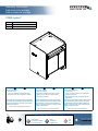
CORE Lectern™
55548 CORE (no cutouts)
55549 CORE (used with worksurface cutouts)
55550 Outer laminate panels
??
Important
Before using this product:
• Read this manual
• Comply with all safety and operating instructions
• Ensure all parts and correct quantities are included
Important
Avant d’utiliser ce produit:
• Veillez à lire ce guide
• Respectez les consignes de sécurité et d’utilisation
• Vériez que vous disposez de toutes les pièces
nécessaires à l’installation
Importante
Antes de utilizar este producto:
• Lea este manual
• Cumpla con todas las instrucciones de prevención de
accidentes y operativas
• Revise que todas las partes y las cantidades correctas
estén incluidas
Any parts damaged during shipment must be reported within 5
days of receipt. To report information regarding missing parts or
damage, to purchase parts or accessories, or if you have any
questions, please contact us.
Thank you for purchasing Spectrum products!
Les pièces endommagées pendant le transport doivent faire
l’objet d’un rapport dans les 5 jours de leur réception. Veuillez
prendre contact avec nous si des pièces manquent ou sont
abîmées, si vous avez des questions, ou encore pour acheter
des pièces ou des accessoires.
Merci pour votre achat d’un produit Spectrum!
Si alguna parte se dañó durante el embarque, deberá reportarla
en un lapso de 5 días a partir de la recepción. Para reportar
cualquier información sobre partes faltantes o dañadas, para
adquirirlas o comprar accesorios, o bien, si tiene alguna duda,
póngase en contacto con nosotros.
¡Gracias por adquirir productos Spectrum!
Owner’s Manual
Le manuel du propriétaire
El manual del propietario
VideoVideo
VidéoVidéo
VídeoVídeo
SpecsSpecs
SpécicationsSpécications
EspecicacionesEspecicaciones
800-235-1262800-235-1262
http://www.spectrumfurniture.com

0192507 Page 2 of 8
X2
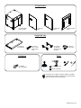
Tools
Assembly tip: Do not tighten component fasteners completely
until all have been installed. Keeping them loose will help with
alignment between parts during assembly.
Hardware
Components
(1) 55548 / 55549
Lectern CORE
(8) 0100167
8-32 x 1/2” PH
thread-cutting
screw
(1pr) 050092
12” Slide set
(bracket screws
included)
(1) Keyboard
Tray assembly
Drill with 3/16” drill bit
(1) Left side
panel
(1) Right side
panel
(1) Audience-side
panel
(12) 038064
#14 x 3/4” PHSM
Keyboard tray
(8) 029019
8-32 Locknut
Drill with 1/4” drill bit
”
”
”

0192507 Page 3 of 8
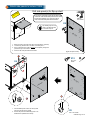
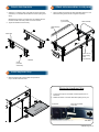
Side panel
1Attach side panels to lectern CORE
(Right side panel shown)
Tip: Masking tape can be
used on the laminate-side
to minimize chip-out.
1. Determine which panel the shelf will be mounted (left or right side)
2. Locate the (8) starter holes in the back of the side panel.
3. Using a drill with a 3/16” drill bit, slowly drill completely through the
panel at the (8) hole locations.
4. Continue with side panel attachment below.
If you have an optional ip-up shelf, the (8) starter holes
on the back of the laminate side panel need to be drilled
through before installing. If you don’t have a ip-up
shelf, continue with side panel attachment below.
Drill with
3/16” drill bit
2
3
1/8”
Side panel
1
Side panel
X12
X8
OPTION
X4 #14 x 3/4”
PHSM
”
X2
#14 x 3/4” PHSM
1. Insert installed panel screws into the keyholes
and push side panel onto CORE.
2. Secure side panel to CORE with (6) #14 x 3/4”
PHSM screws (installed from inside).

0192507 Page 4 of 8
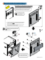
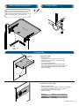
2Attach audience-side panel to lectern CORE
Audience-side panel
Tip: Masking tape can be
used on the laminate-side
to minimize chip-out.
If you have an optional logo panel, the (6) starter holes on
the back of the laminate side panel will need to be drilled
through before installing. If you don’t have a logo panel,
continue with audience-side panel installation below.
Drill with
1/4” drill bit
Drill audience-side panel for logo panel
1. Locate the (6) starter holes in the back of the audience-side panel.
2. Using a 1/4” drill bit, slowly drill completely through the panel at
the 6 hole locations.
3. Align the logo panel studs with the drilled holes and secure with
(6) 1/4” washers and (6) 10-32 keps nuts.
4. Continue with logo and audience-side panel installation below.
X6
OPTION
3
2
410-32
Keps nuts
Optional logo panel
1/4” Flat
washers
Audience-side panel
X6 X6
1
Audience-side panel
”
Note: Using key, turn lock cam 90° counterclockwise
before installing the audience-side panel, then lock
after panel is in place.
Note: The two metal channel sup-
ports on audience-side panel “hook”
over horizontal bracket on CORE.
”

0192507 Page 5 of 8
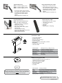
1. Attach the ‘L’ brackets to each outer slide with screws (included
with slides). The brackets will be attached “inboard” (facing each
other).
Multiple height positions / mounting holes are available with the
brackets-use the same hole position on all four brackets.
2. Tighten the bracket screws securely.
Screw
(included
with slides)
Outer slide
‘L’ Bracket
1. Slide the keyboard tray into the slides and push all the
way in until two clicks are heard.
1. Align and attach the left and right slide assemblies with 8-32 x 1/2”
PH thread-cutting screws, but do not tighten completely.
Mid-panel
Slide assembly
(right)
Slide assembly
(left)
8-32 x 1/2” PH
thread-cutting
screw
(2 per bracket)
4Attach slide assemblies to mid panel
5Install keyboard tray
3Attach slide brackets
1. To remove the tray from the slides, locate the plastic lever on
each slide
2. Release the levers on the both slides while pulling the tray out
Push here to release
inner slide
Removing keyboard tray
Inner slide
Outer slide
8-32 Locknut
(2 per bracket)
Keyboard Tray

0192507 Page 6 of 8
Flip-Up Shelf - 55540
• Matching laminate
• 15.25”W [38.7 cm] x 26”D [66 cm] x 1”H [2.54 cm]
• Shelf brackets lock into place in the upright position
• Includes 2” grommet
• 35 lb [15.9 kg] weight capacity
• Also available with White Chalk Dry Erase laminate.
have the same edgeband color as the outer panels.
• Customer-installed
26”D
[66 cm]
15.25”W
[38.7 cm]
Customized Logo Panel - 55199
• Attaches to audience-side
• Available with black, white, matching, or printed laminate backer
• To get panel customized-contact Spectrum for details
•
• Customer-installed
Dimensions: 30”W [76.2 cm] x 12”H [30.48 cm]
Available logo area: 28”W [71.1 cm] x 10”H [25.41 cm]
Unit weight: 6 lb [2.7 kg]
Shipping weight: 8 lb [3.6 kg]
Accessories
6
Note: If you have the optional ip-up shelf, it can be
attached after the side panel is installed. Align the
shelf brackets with the drilled holes and attach to the
side panel using (8) 8-32 x 1-1/2” PHM screws.
X8
8-32 x 1-1/2”
PHMS
Flip-up shelf
7Locking casters

0192507 Page 7 of 8
Dual Flat Panel Monitor Arm - 95533
• Weight range: 3.5-13 lb per monitor
• Six mounting options (clamp, thru-desk,
wall, grommet hole, side bolt, reverse wall)
• Compatible with all VESA® monitors-
includes 75mm and 100mm VESA®
adapters
• Cable management concealed in arm
Flat Panel Monitor Arm
95512 - for monitors weighing 2-13 lb
95522 - for monitors weighing 7.5-25 lb
95509 - for monitors weighing 12-31 lb
• Six mounting options (clamp, thru-desk,
wall, grommet hole, side bolt, reverse wall)
• Compatible with all VESA® monitors -
includes 75mm and 100mm VESA®
adapters
• Cable management concealed in arm
7-Outlet Power Strip - 99024
• Electrical Rating: AC 125V, 15 Amps
• 1000 Joules surge capacity
• 12’ cord length
• LED switch
• UL Listed
• Shipping weight: 1.9 lb [.86 kg]
Heavy-Duty Monitor Arm
95539 - without USB & multimedia ports
95540 - with USB & multimedia ports
• Adjustable gas spring counterbalance
• Weight range: 2.2-33lb
• Fits most 17-35” monitors
• Quick-release 75mm, 100mm, VESA®
mounting plate
• Clamp or grommet mounting
• Optional (2) USB 3.0 ports and (2) 3.5mm
jacks for mic / headphones
• Cable management channel
Power Module - 99058
• (2) AC power receptacles
• (2) USB charge ports
•
• Thumbscrew clamps
• Requires worksurface cutout made by customer
•
• Available in black, silver, or white
• Customer-installed
EM Wireless Charging Pad - 99057
• Uses electromagnetic technology to charge Qi V1.2
compliant IC devices ("Qi" enabled)
•
• Security tab prevents theft
• Customer-installed
•
Cutout required: 3" dia (by customer)
Input: DC 5V (with included DC5V.2A power adapter)
Output: 5W max (with included DC5V.2A power adapter)
Power cord: 8’ [244 cm] with DC jack
Dimensions: 3.5” dia [8.9 cm] x 1.125”H [2.9 cm]
Shipping weight: 1 lb [.45 kg]
Note: The unit requires a 7” diameter of clearance to work with Qi-
enabled phones placed in any orientation. The 3” dia cutout should
be located on the worksurface at least 3.5” from any edge.
Cutout required: 5.65”W [14.35 cm] x 1.65”D [4.19 cm]
Power cord: 10’ [305 cm] 14AWG *3C power cord
Power receptacles: 125V, 60hz, 15A tamper-resistant
USB charging ports: 2.1A (10.5W) (not data-compatible)
Dimensions: 6.38”W [16.2 cm] x 2.36”D [6 cm] x 3.54”H [9 cm]
Unit weight: 2 lb [.9 kg]
Shipping weight: 2.35 lb [1 kg]
See spectrumfurniture.com for the latest
accessories and detailed warranty information.

0192507 Page 8 of 8
Important Safety & Care Information
• Read these instructions before assembly or operation.
• Do not allow children to move the lectern.
• Proceed slowly and carefully when moving the lectern.
• For indoor use only. Do not install or store the lectern where it will be exposed
to moisture.
• Do not block the ventilation openings.
• Avoid uneven loading of the equipment into the lectern. Uneven weight
distribution could cause the lectern to tip when the lectern is moving.
• Do not allow anyone to sit, stand, or climb on the lectern.
• Use a damp, soft-cloth, or sponge, with mild soap or detergent solution to clean
dirty surfaces. Do not use harsh solvents or abrasives.
• This lectern is intended for institutional use. It does not have any user-
serviceable parts or user-maintenance requirements. If servicing is necessary,
please contact Spectrum Industries for assistance.
Electrical Safety:
• Do not plug the power cord into an extension cord.
• Inspect power cords for damage before each use. Do not use power cords
that are damaged.
• Unplug power cord from electrical outlet by gripping the cord. Do not unplug
the power cord by pulling only on the cord.
• Do not step on, drive over, drag, or place objects on the power cord.
• For added safety, plug the lectern into a grounded outlet controlled by a GFI
(Ground Fault Interrupter) circuit breaker.
• Electrical devices are not toys. Children are often unaware of the hazards
associated with electrical devices. This lectern must always be used by
adults or with adult supervision.
Warning
designed to support audio and/or video equipment may result in death or
serious injury due to the furnishing collapsing or over turning onto a child.
Warning - Death or serious injury may occur when children climb on audio
and/or video equipment furniture. A remote control or toys placed on the
furnishing may encourage a child to climb on the furnishing and as a result the
furnishing may tip over on to the child.
925 FIRST AVENUE, CHIPPEWA FALLS, WI 54729 / 800-235-1262 / 715-723-6750 / WWW.SPECTRUMFURNITURE.COM
Warranty
1-800-235-1262
Toll-free HELPLINE
© 2021 Spectrum Industries Inc., All rights reserved.
We will make it right for you!
Thanks for choosing Spectrum! Spectrum is committed to provide complete customer satisfaction.
Each of our products is manufactured from the best materials available and each product is strin-
gently monitored throughout the production process through our P.A.C.E. program (Product Assur-
ance to meet Customer Expectations).
We expressly warrant that Spectrum products will be of good quality and workmanship and free from
defect for the period set out in the warranty from the date of delivery.
For a listing of all product specifi c warranty terms please visit our website at:
https://www.spectrumfurniture.com/en/resources/purchasing-terms-warranty
925 FIRST AVENUE, CHIPPEWA FALLS, WI 54729 / 800-235-1262 / 715-723-6750 / WWW.SPECTRUMFURNITURE.COM
© 2021 Spectrum Industries Inc., All rights reserved.
We will make it right for you!
Thanks for choosing Spectrum! Spectrum is committed to provide complete customer satisfaction.
Each of our products is manufactured from the best materials available and each product is strin-
gently monitored throughout the production process through our P.A.C.E. program (Product Assur-
ance to meet Customer Expectations).
We expressly warrant that Spectrum products will be of good quality and workmanship and free from
defect for the period set out in the warranty from the date of delivery.
For a listing of all product specifi c warranty terms please visit our website at:
https://www.spectrumfurniture.com/en/resources/purchasing-terms-warranty
Pending
-
 1
1
-
 2
2
-
 3
3
-
 4
4
-
 5
5
-
 6
6
-
 7
7
-
 8
8


