MooreCo Rapport Glass Wall Assembly Instructions
- Tipo
- Assembly Instructions

Rapport Glass Wall - Classroom Series
UPDATED AS OF: 10/08/2019 1 of 12
INSTRUCCIONES DE ENSEMBLAJE
NO LA TIRE
INSTRUCTIONS DE MONTAGE
NE PAS JETER
ASSEMBLY INSTRUCTIONS
DO NOT THROW AWAY!

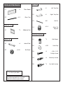
P1 Glass Board
P2 Glass Tray
A1 Adhesive Pad
B1 Joiner Plate
B2 Set Screw
Parts and Hardware
UPDATED AS OF: 10/08/2019 2 of 12
C1 Left Tray End
C2 Right Tray End
C3 Roll Pin
C4 Nylon Tip
Adjuster
D1 Wall Mount
D2 Outer Cap
D3 #10 x 1 1/4”
Phillips Screw
D4 Masonry Anchor
D5 Dry Wall Anchor
*P
x1/2
*X
*X
x2/B1
x1
x1
x0/1
x2/*P
*X
x1/D1
*X
*X
*X
Adhesive Pack
Tray Pack
Mounting Hardware
Joiner Pack
This page includes only the hardware provided
that may be required for this instruction.
Additional hardware may be inluded.
*P - # of panels per order
*X - custom # per order

For full product warranty details, please visit:
Para obtener información sobre la garantía del producto, consulte este sitio (ingles):
Pour plus d’informations sur la garantie du produit, consultez ce site (anglais):
For questions on assembly or missing/damaged parts, please contact us using the
following information.
Para preguntas sobre el ensamblaje o piezas faltantes o dañadas, por favor
contáctenos usando la siguiente información.
Pour toute question sur le montage l-assamblage manquantes ou endommagées,
veuillez nous contacter en utilisant les l’information ci-dessous.
To register your product for warranty, please visit:
Para registrar la garantía del producto, vea este sitio (en ingles):
Pour enregistrer la garantie de votre produit, consultez ce site (en anglais):
Review full assembly instructions and
check that all parts are present before
beginning assembly. Heavy or large
furniture may require multiple persons in
order to properly assemble. If you have
questions regarding assembly, contact
the manufacturer before continuing.
Damage due to incorrect assembly may
not be covered by warranty. Do not use
product unless all screws are tight. Check
all screws for tightness at least every
six months. If parts are broken, missing,
damaged, or worn, stop use of the product
until repairs are made by your dealer using
factory authorized parts.
WARNINGS AND DISCLAIMERS
WARRANTY
CARE & MAINTENANCE
PRODUCT REGISTRATION
UPDATED AS OF: 10/08/2019 3 of 12
Phone:
1.800.749.2258
(Monday – Friday, 8AM – 5PM
Central Time)
http://moorecoinc.com/warranty
https://moorecoinc.com/register
Email:
support@moorecoinc.com
Previo a comenzar el proceso de
ensamblaje favor de revisar las
instrucciones y asegurarse que cuenta con
todas las partes y materiales necesarios.
Es posible que los muebles grandes o
pesados, requieran mas de una persona
para ensamblarlos correctamente. Por
favor contacte al fabricante directamente
si tiene alguna duda o pregunta antes de
continuar con el proceso de armado del
producto. La garantía no cubrirá daños
que ocurrieron por errores cometidos
durante el proceso de ensamblaje. Todos
los tornillos deben estar ajustados previo
el uso del producto. Debe revisar los
tornillos periódicamente, por lo menos
cada seis meses y asegurarse de que
estén bien ajustados. Por favor detenga
el uso del producto si partes del producto
se pierden, rompen, se deterioran por uso
o se rompen. Favor de contactar a su
distribuidor para que le envíen las partes
necesarias o realice las reparaciones
necesarias con partes autorizadas por el
fabricante.
Avant de commencer l’ assamblage
veuillez consulter les instructions
complètes et vérier si vous avez toutes
les pièces nécessaires. Ill est possible que
plusieurs personnes soient nécessaires
pour assemble des meubles grand ou
lourds. En cas de doute sur l assamblage
contactez le fabricant avant de continuer.
Les dommages encourus pendant
l’assamblage ne seront pas couvert par
la garantie. Ne pas utiliser le produit sans
vérier que tous les vis soient serrées.
Vériez que les vis sont serrées au moins
tous le 6 mois. Si aucune pièce se casse,
manque, est endommagée ou usée,
arrêtez d’ utiliser de produit jusqu’à ce
que le vendeur le repaire a l’aide de pièces
autorisées par la fabricant.
ADVERTENCIAS Y RENUNCIAS AVERTISSEMENTS

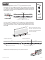
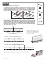
STEP 1A
UPDATED AS OF: 10/08/2019 4 of 12
Assembly for single piece tray. See STEP 1B for two piece tray assembly.
Insert joiners (B1) into tray bottom channel. Slide in two joiners for every panel
(i.e. 4 joiners for 2 panels). Move joiners along bottom channel until one hole
on every joiner is lined up with a pre-drilled hole. Be sure not to cover any pre-
drilled holes by mistake.
Complete tray assembly by pressing in Tray Ends (C1 and C2).
Single Tray Single Panel: Single Tray Multi Panel:
Panel Panel A Panel B
Adjuster Outside/Set Screw Inside
Insert set screws (B2) and adjusters (C4) through joiners. All pre-drilled holes in
tray bottom will need an adjuster. Any hole in joiner not aligned with a hole in
the tray should receive a set screw. See pictures below for joiner and set screw
positioning.
Adjusters use allen wrench. Thread
until head is flush with top of channel.
Set Screws use flat-head screwdriver.
Thread until hand tight.
Adjusters Inside near Panel Seam
Pre-drilled holes at Panel Seams and tray edges
Panel Seam
Right TrayLeft Tray
(A S) (S A) (A S) (S A) (A S) (S A)
A - Adjuster
S - Set Screw
B1
B2
C4
C1
C2

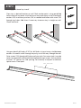
STEP 1B
Next slide in additional joiners from ends of tray. Insert two joiners for every
panel, half on each side of the splice (i.e. for 4 panels insert 4 joiners from the
left and 4 from the right). Move joiners along bottom channel until one hole
on every joiner is lined up with a pre-drilled hole. All pre-drilled holes in tray
bottom will need an adjuster (C4). Any hole in joiner not aligned with hole in
tray should receive a set screw.
Assembly for two piece glass board tray.
First splice two tray pieces together. Use one joiner (B1) on bottom channel
and another on back channel with 2 set screws each (B2). These joiners should
not cover any pre-drilled holes in tray. A roll pin should also be added beneath
the tray’s front lip.
Adjusters use allen wrench. Thread
until head is flush with top of channel.
Set Screws use flat-head screwdriver.
Thread until hand tight.
Panel Seam at Tray Splice (Even Number of Panels)
Panel Seam and Tray Splice Offset (Odd Number of Panels)
Panel 1 Panel 2
Panel 1 Panel 2 Panel 3
Tray 2
Tray 1
Complete tray assembly by pressing in Tray Ends (C1 and C2).
Panel Seam
Pre-drilled holes at Panel Seams and edges of both trays
UPDATED AS OF: 10/08/2019 5 of 12
Tray 1
Tray 2Tray 1
Right TrayLeft Tray
A - Adjuster
S - Set Screw
(S A) (S A)
(S A) (S A) (S A)
(A S)
(A S) (A S) (A S)
(S S) (A S)
(S S)
B1
B2
C3
C4
C1
C2

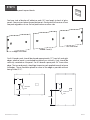
STEP 2
UPDATED AS OF: 10/08/2019 6 of 12
Place tray in desired location on wall. Mark anchor points using pre-drilled
holes in back of tray piece. Install anchors at any mark not on a stud. Use drywall
anchors (D5) or masonry anchors (D4) as needed and follow with screw (D3)
through tray holes. Add shims if necessary to ensure tray is straight on wall.
Check with level.
Using an electril drill and a 3/16” bit, drill holes in tray at every stud between
anchors. Be careful to drill through tray only, not all the way through the wall.
Drive screws (D3) through drill holes and into studs. For some studs it may be
necessary to pre-drill smaller pilot holes before driving in screws. Picture shown
assumes 16” centers for stud spacing. For masonry or drywall installations
space screws 2 feet apart. 16" Centers
Mounting glass board tray to wall.
Drywall Masonry
D3
D4
D5

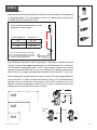
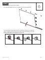
STEP 3
UPDATED AS OF: 10/08/2019 7 of 12
Next determine horizontal mount placement. One mount should be spaced
within 6” in from either edge of each panel. For 4ft wide panels this is sufficient.
For 6ft and 8ft wide panels add 1 and 2 more mounts respectively, evenly
spaced. Use pre-drilled holes in tray as a reference to identify where panel
seams will be. For edges of board note that panels will extend 0.5-1” past tray.
After marking wall, pre-drill holes for screws. Pre-drill 1/8” holes if going directly
into a stud and 1/4” holes if using either anchor. Screws (D3) should be driven
through slots on wall mounts into anchors (D4 or D5) or directly into stud.
Mounts should be snug against wall but not so tight as to prevent them from
sliding up on the wall with the screws in place.
Install wall mounts.
Measure vertical distance up from tray where screws for mounts will be placed.
using guide below. This should place screws 3/4” below top of panel once
installed. Mark this distance on wall.
Distance between top edge of tray to
wall mount screw center:
Panel Height (ft) Distance X (“)
4 ft 44 7/8”
6 ft 68 1/2”
8 ft 92 1/8”
X
4x4
4x6
4x8
D1
D3
D4
D5
Dry Wall
Masonry
Wall
3/4”
6”
Panel Top Edge
Panel Seam
***Due to slight variations in walls make
sure to check measurements first with
one panel and make adjustments before
proceeding to install all wall mounts

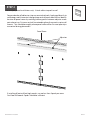
STEP 4
UPDATED AS OF: 10/08/2019 8 of 12
For multiple panel installations only - Attach adhesive pads to wall.
If installing 6 feet or 8 feet high panels, use no less than 3 pads per seam.
For 4 foot tall boards 2 pads should be sufficient.
Remove backer off adhesive strips on one side of pads. Apply pad directly to
wall being careful to center it along where vertical panel seam will be. Identify
location of panel seams by marking halfway points between adjuster screw
pairs above tray. Picture a vertical line extending from these marks up to wall
mounts. This should be roughly where panel seam will be. Be sure tape strips
are vertical during placement.
B1
Panel Seam
Adjusters

STEP 5
UPDATED AS OF: 10/08/2019 9 of 12
Peel one side of backer off adhesive pads (B1) and apply to back of glass
panels. See pictures below for pad placement. Each panel will receive at least
two pads regardless of size. Do not peel backer on other side.
Attach adhesive pads to panel backs.
ADHESIVE
PAD
ADHESIVE
PAD
ADHESIVE
PAD
ADHESIVE
PAD
ADHESIVE
PAD
ADHESIVE
PAD
For application of self adhesive pads for glass boards,
peel one side of the backer from the pad and apply to
the board per the drawings. Next, peel the other side
before mounting on the wall while carefully position
the the panel left to right before applying pressure
against the wall.
For application of self adhesive pads for glass boards,
peel one side of the backer from the pad and apply to
the board per the drawings. Next, peel the other side
before mounting on the wall while carefully position
the the panel left to right before applying pressure
against the wall.
For application of self adhesive pads for glass boards,
peel one side of the backer from the pad and apply to
the board per the drawings. Next, peel the other side
before mounting on the wall while carefully position
the the panel left to right before applying pressure
against the wall.
3X4 Vertical Mount
3X4 Horizontal Mount
4X6 Horizontal Mount
4X6 Vertical Mount
4X8 Horizontal Mount
4X8 Vertical Mount
12"
CENTER
12"
CENTER
12"
CENTER
12"
CENTER
24"
CENTER
24"
CENTER
ADHESIVE
PAD
ADHESIVE
PAD
ADHESIVE
PAD
ADHESIVE
PAD
ADHESIVE
PAD
ADHESIVE
PAD
For application of self adhesive pads for glass boards,
peel one side of the backer from the pad and apply to
the board per the drawings. Next, peel the other side
before mounting on the wall while carefully position
the the panel left to right before applying pressure
against the wall.
For application of self adhesive pads for glass boards,
peel one side of the backer from the pad and apply to
the board per the drawings. Next, peel the other side
before mounting on the wall while carefully position
the the panel left to right before applying pressure
against the wall.
For application of self adhesive pads for glass boards,
peel one side of the backer from the pad and apply to
the board per the drawings. Next, peel the other side
before mounting on the wall while carefully position
the the panel left to right before applying pressure
against the wall.
3X4 Vertical Mount
3X4 Horizontal Mount
4X6 Horizontal Mount
4X6 Vertical Mount
4X8 Horizontal Mount
4X8 Vertical Mount
12"
CENTER
12"
CENTER
12"
CENTER
12"
CENTER
24"
CENTER
24"
CENTER
For 6 ft boards pads should be placed approximately 12” from left and right
edges whether panel is positioned horizontally or vertically. Pads should be
vertically centered on the panel. For 8 ft boards space pads 24” from either
edge. The two end panels should get two extra pads applied to each to brace
the edges. These should be placed as close to the edge as possible without
being visible (2-3”).
B1
Middle Panel(s)
Left End Panel
Right End Panel

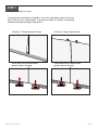
STEP 6
UPDATED AS OF: 10/08/2019 10 of 12
Insert bottom of panel into tray at an angle then push top towards wall.
Set panels into tray and secure to mounts.
Once top of panel is positioned vertically, slide down wall mounts into position
shown. Screw in at least two outer caps (one at each end of panel) just to hold
panel in place. Repeat until all panels are up on wall.
D2

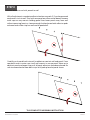
STEP 7
UPDATED AS OF: 10/08/2019 11 of 12
Using adjusters previously inserted in tray, raise and lower panels to ensure
flush seams across entire board. Use pictures below as guides in deciding
where to make panel height adjustments.
Adjust panel height at seams.
Situation 1: Gap at bottom of seam Situation 2: Gap at top of seam
Raise adjusters on one or both
panels nearest the gap.
Lower adjusters on one or both
panels nearest the gap.

STEP 8
UPDATED AS OF: 10/08/2019 12 of 12
With all adjustments complete, adhesive backers on pads (A1) can be removed
and panels stuck to wall. Start with one panel on either end of board. Remove
outer caps on any mounts holding panel then lower panel away from wall
without removing from tray. Lower enough that backer on both adhesive pads
on board and visible strips on wall can be peeled off.
Remove adhesive and stick panels to wall.
Carefully push panel back into wall so adhesives contact wall and panel. Once
complete screw in outer caps to all wall mounts to secure panel. Move on to
adjacent panel and repeat step until all panel adhesives have been placed. Be
sure to remove backer from both strips of all pads placed at panel seams.
THIS COMPLETES ASSEMBLY INSTRUCTION
-
 1
1
-
 2
2
-
 3
3
-
 4
4
-
 5
5
-
 6
6
-
 7
7
-
 8
8
-
 9
9
-
 10
10
-
 11
11
-
 12
12


MooreCo Rapport Glass Wall Assembly Instructions
- Tipo
- Assembly Instructions
in altre lingue
- English: MooreCo Rapport Glass Wall
Altri documenti
-
Spectrum Industries 55548BKBKB Manuale del proprietario
-
MULTIPLEX Funcub Manuale del proprietario
-
Pella 80KM0103 Manuale utente
-
MULTIPLEX 21 4164 Manuale del proprietario
-
 Hangar 9 P-47D-1 Thunderbolt 60 Manuale utente
-
-
-
 Hangar 9 HAN2765 Manuale del proprietario

