
1
Schwimmer-BausatzSchwimmer-Bausatz
Schwimmer-BausatzSchwimmer-Bausatz
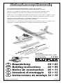
Schwimmer-Bausatz
z.B. für MiniMag und vergleichbare Modelle bis ca. 650 g in der Landversion.
Die Schwimmer sind fertig geschäumt aus dem robusten Partikelschaum „ELAPOR“.
Floats Kit e.g. for MiniMag and comparable models up to about 650 g weight (land-based version).
The floats are supplied as ready-made items moulded in the robust particle foam "ELAPOR".
A utiliser par ex. : avec le MiniMag et des modèles de même type qui, en version terrain, ne dépasse pas les
650g. Les flotteur sont complètement terminés en mousse ''ELAPOR'' particulièrement résistante aux chocs.
Scatola di montaggio per galleggianti p.es. per MiniMag e modelli simili fino a ca. 650 g di peso.
I galleggianti sono costruiti con robusto materiale espanso "ELAPOR".
Kit de flotadores P. Ej., para Minimag o modelos similares con un peso inferior a 650g. en su versión con tren
de aterrizaje. Los flotadores están fabricados con robustas partículas de espuma "ELAPOR"
Im Winter auch auf Schnee - ´ne Super-Schau!
Also great on snow in Winter - looks great!
En hivers même sur la neige - que du fun!
Anche d'inverso sulla neve - il divertimento è assicurato!
En invierno, también sobre la nieve ¡Súper espectacular!
GB
D
E
I
Bauanleitung 02 + 03
Building instructions 04 + 05
Notice de construction 06 + 11
Istruzioni di montaggio 12 + 13
Instrucciones de montaje 14 + 15
© Copyright by MULTIPLEX 2006 Version 1.0
ELAPOR®
Schwimmerbausatz weiss / white
z.B. für MiniMag # 73 3069
F
Schwimmer-BausatzSchwimmer-Bausatz
Schwimmer-BausatzSchwimmer-Bausatz
Schwimmer-Bausatz

4
GB
Floats kit, white, e.g. for MiniMag # 73 3069
These floats are suitable for models with a maximum weight of around 650 g in standard form. Of course, the floats are
normally intended for use on water, but they also work well on snow, and this is a very exciting and attractive option.
These instructions describe the method of fitting and using the floats in conjunction with the MiniMag. However, at the
appropriate point we also provide general notes on their use on other models of similar size. If you wish to fly the MiniMag with
the floats attached, we recommend that you also install the MULTIPLEX "Sport" power set: BL-X 22-18 # 33 2627.
Important: the floats are made of ELAPOR® - not Styrofoam™!
Adhesive and activator:
Use medium-viscosity cyano-acrylate glue (not styrofoam cyano). It is important to use activator when using cyano. Epoxy
adhesives produce what initially appears to be a sound joint, but the bond is only superficial, and the hard resin breaks away
from the parts under load. Hot-melt glues can also be used.
Please take care when handling cyano-acrylate adhesives. These materials harden in seconds, so don't get them on your
fingers or other parts of the body. We strongly recommend the use of goggles to protect your eyes. Keep the adhesive out
of the reach of children.
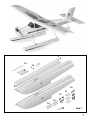
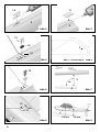
Please check the contents of your kit with reference to the
Parts List and Fig. 1.
Assembling the floats:
Glue pairs of 3 x 8 x 40 mm plastic plates 10 together using
cyano to form the front mounting plates in the floats 2.
Fig. 2
These plates can now be glued in the recesses at the front of
the floats, but first check that they fit neatly. When you are
confident, spray activator on the mounting plates and allow it
to air-dry.
Apply high-viscosity (thick) cyano to the recesses in the floats,
and press the mounting plates all the way into them in one
movement; they should end flush with the surface.
Fig. 2
Caution!
Hold the floats pointing away from yourself, as excess glue
might be forced out and spray into your face when you push
the plates into the recesses.
Glue the rear mounting plates 11 to the rear float recesses,
again using cyano.
Fig. 3
At the front the floats are attached to the standard
"undercarriage unit" using the saddle clamps 12 and the
screws 13 (4 x). Place the saddle clamps 12 on the mounting
plates 10, mark the position of the holes for the screws 13
using a bradawl (pointed instrument), and drill 1.5 mm Ø
pilot-holes. Now fix the saddle clamps to the mounting plates
using the screws.
Fig. 4
At the rear bend the "undercarriage unit 3" to the shape shown
in the drawing (drawn full-size in Fig. 5 on page 9), and fix it to
the rear mounting plates 11 (3 x) using the flat saddle clamps
14 and the associated screws 15. Mark the hole positions
using a bradawl and drill 1.5 - 1.7 mm Ø pilot-holes. The
clamps can now be fitted with the screws.
Fig. 6
Aligning the floats
Position the rear undercarriage unit 3 in such a way that the
spreader plate 11 (3 x 18 x 30 mm) can be glued centrally to
the underside of the fuselage between the undercarriage unit
and the fuselage, maintaining the spacing as stated in Fig. 9.
Screw the rear undercarriage unit 3 to the fuselage-mounted
plate 11 using the screws 15 and the flat saddle clamps 14.
Fig. 7
Now glue the rear mounting plate 11 to the underside of the
fuselage, at the front of the flat area. Fig. 8
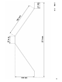
Mounting the floats on similar models
The straight line formed by the rear part of the floats aft of the
step (underside) must be set at the correct angle relative to
the "zero datum" (a line parallel to the tailplane): the difference
between the front and rear should be 20 mm, as shown in
Fig. 9.
The float step should be located vertically below the model's
Centre of Gravity (CG) when the aeroplane is in the take-off
position. At the "take-off" position the wing should now be at
an angle of attack of around 7°.
(Caution: this is not the same as the longitudinal dihedral,
which is around 2° with models of this type.)
The function of the water rudder
The water rudder is absolutely essential for steering the model
on the water, and is also helpful when the model is flying.
When the model is in the air the additional rudder area is
required to compensate for the change in the aircraft's side
area distribution caused by the floats. If you wish to fly the
model from snow with the floats attached (incidentally this
works extremely well, but varies according to the quality of the
snow), the water rudder must be left in place.
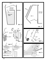
Making the water rudder
The water rudder consists of a shaped wire frame 4 and a
DEPRON™ panel 5. Fig. 10. First bend the wire to the shape
shown in the full-size drawing using a pair of pliers. Note that
the wire is supplied overlength.
Lay the prepared wire frame on the DEPRON panel 5 and
transfer its shape to the foam by pressing down using a piece
of hardwood or similar. The water rudder can now be cut out
using a sharp balsa knife, and fitted inside the wire frame.
Apply strips of clear adhesive tape all round the rudder to
attach the wire frame to the Depron.
Fig. 10
Attaching the water rudder
In order to attach the water rudder, you must have fitted a
steerable tailwheel to the model beforehand. If your model is
not yet fitted with a tailwheel, install it at this juncture as
described in the "MiniMag" building instructions. Figs. 11 - 13
The water rudder is clamped to the model's tailwheel wire
using two collets 16, fitted with grubscrews 17. This method
makes it possible to remove the water rudder again at any
time. Tighten the grubscrews using the allen key 18 supplied.
Fig. 14

5
If you wish to fit the floats to the MiniMag, the integral foam
skid at the tail end of the fuselage must be cut off using a
sharp balsa knife, and the area cleaned up neatly.
Fig. 13
A length of plastic sleeve 19 is supplied in the kit as a bush for
the tailwheel wire in the fuselage. If this sleeve is not already
fitted to your model, there is no need to install it.
For "land operations" simply undo the collets and remove the
water rudder; the tailwheel can now be re-fitted. Fig. 15
Gilding the lily
The kit is supplied with a pair of decal stripes 6, which can be
applied to the outside of the floats.
A few words on flying from water
A certain amount of flying experience and skill is required for
successful operations from water. Water may seem softer,
but the model usually gets off no more lightly from a hard
landing or a crash on water than on terra firma, and the
receiving system components may also be damaged or
completely ruined if water gets inside them, so it pays to be
careful.
For the first few test-flights we recommend that you wait for a
day with as little breeze as possible. Allow the model to
accelerate smoothly and slowly, and keep the nose exactly
into wind using the water rudder. The water rudder must
remain in the water until the model lifts off, otherwise you will
lose control of the aeroplane. If the water rudder comes out of
the water prematurely, the model will respond by turning
sharply, and this may even cause it to turn over. The rudder
can be kept in the water by applying up-elevator, and not
releasing the elevator until the moment the aeroplane lifts off.
As the model accelerates, the floats will slowly rise out of the
water, until the rear section - aft of the step - is completely
clear of the surface. At this stage, when the model is planing
on the front surface of the float, you can take off by applying a
definite "up-elevator" command.
Caution: do not even think about trying a take-off from water
without the water rudder fitted.
Rise-off-water take-offs work best from a water surface with
very slight waves; if it is absolutely smooth, the take-off run
will be longer.
If the water's surface is completely still, you can generate
waves by running the model across the line of flight first; this
will enable the aircraft to lift off more easily.
Carry out the landing approach at a shallow angle directly
into wind at low speed and with the throttle slightly open (high
idle speed).
Maintain some reserve battery energy at landing time, so that
you can safely taxi the model back to the bank. Take particular
care to keep clear of any bathers and other water sports
enthusiasts.
All of us in the MULTIPLEX team wish you many hours of
pleasure building the floats and flying your float-equipped
model.
Klaus Michler
Parts List - Floats kit e.g. for MiniMag # 73 3069
Part No. Description Material Dimensions
No. off
1 1 Instructions
2 2 Float ELAPOR, white Ready made
3 1 Rear undercarriage unit Spring steel 1.3 Ø x 400 mm
4 1 Wire for water rudder / tail wheel Spring steel 1.3 Ø x 400 mm
5 1 Water rudder DEPRON, white 3 x 40 x 60 mm
6 2 Decal strip Ready made 8 x 400 mm
Small items
10 4 Front mounting plate Plastic 3 x 8 x 40 mm
11 3 Rear mounting plate Plastic 3 x 18 x 30 mm
12 2 Saddle clamp Plastic Ready made
13 4 Saddle clamp screw Metal 2.2 x 16 mm
14 4 Flat saddle clamp Plastic Ready made
15 8 Flat saddle clamp screw Metal 2.2 x 13 mm
16 2 Collet Metal 2.7 mm Ø
17 2 Socket-head grubscrew Metal M3 x 3 mm
18 1 Allen key Metal 1.5 mm A/F
19 1 Water rudder bush Plastic sleeve 3 Ø / 2 Ø x 90 mm

7
2
2
3
4
5
6
10
10
11
12
13
14
15
18
19
16
17
Abb.1

8
Abb.2 Abb.3
Abb.4
Abb. 1:1 Seite/Page 9 Abb.5
Abb.9
Abb.6 Abb.7
Abb.8
2
10
11
2
12
13
15
15
11
14
170 mm
150 mm
10
3
3
2

9
27 mm
66 mm
270 mm
120 mm
21 mm
M 1:1 Abb.5

10
Abb. 11
Stahl/Steel
Ø 1,3 mm
Depron®
3 mm
M 1:1
M 1:1
Abb. 12
19
Stahl/Steel
Ø 1,3 mm
4
4
5
Abb. 14
16+17
Ø 26
# 73 3199
Heckrad=Option. Die Teile
liegen dem BK nicht bei!
Tailwheel = option. Parts not
included in the kit
16+17
Abb. 10
30
Abb.13
8
CA
Abb.15

16
MULTIPLEX Modellsport GmbH & Co.KG Neuer Weg 2 D-75223 Niefern-Öschelbronn www.multiplex-rc.de
-
 1
1
-
 2
2
-
 3
3
-
 4
4
-
 5
5
-
 6
6
-
 7
7
-
 8
8


in altre lingue
- English: MULTIPLEX 73 3069
Documenti correlati
-
MULTIPLEX Schwimmer Satz Funman Manuale del proprietario
-
HiTEC MiniMag RR Manuale del proprietario
-
-
-
-
-
-