CARLO GAVAZZI SHOWEAGPS Guida d'installazione
- Tipo
- Guida d'installazione

SHOWEAGPS
Weather Station for Modbus
Technical specifications and installation instructions
Stazione meteorologica per Modbus
Dati tecnici ed avvertenze per l'installazione
Estación meteorológica por Modbus
Datos técnicos e instrucciones de instalación
EN
IT
ES
www.gavazziautomation.com


Technical specifications and installation instructions
EN
SHOWEAGPS
Weather Station for Modbus
www.gavazziautomation.com

EN 4 Description
SHOWEAGPS Weather Station • Version: 03.05.2019 • Technical changes reserved. Errors reserved.
1. Description
The SHOWEAGPS Weather Station measures temperature, wind speed and bright-
ness (eastern, southern and western sun) and recognizes precipitation.
The SHOWEAGPS receives the UTC signals (Universal Time Coordinated) as well as
the site coordinates via an integrated GPS receiver. The direction of the sun (azimuth)
as well as its height (elevation) are calculated and indicated, too.
Data are usually output after a request made by the Modbus master via a 2-wire RS485
connection. Furthermore, the weather station can communicate with a PC.
The weather station has four ports; the data output is made via the terminals A and B.
Here, an IC is used that can operate with up to 128 participants on one bus (TI
SN65LBC184D).
Functions:
Brightness measurement with three separate sensors for east, south and west.
Recognition of twilight/dawn with special filters
• Wind measurement: The wind strength measurement takes place
electronically and thus noiselessly and reliably, even during hail, snow and
sub-zero temperatures. Even turbulent air and anabatic winds in the vicinity of
the weather station are recorded
• Temperature measurement
• Heated precipitation sensor (1.2 watts): No false reports as a result of fog or
dew. Dries quickly after precipitation has stopped
• Integrated GPS receiver. Output of UTC (Universal Time Coordinated), position
(degree of longitude and latitude) and position of the sun (azimuth, elevation)
1.1. Technical specifications
Housing Plastic material
Colour White / translucent
Mounting On-wall
Protection category IP 44
Dimensions approx. 96 × 77 × 118 (W × H × D, mm)
Weight approx. 160 g
Ambient temperature Operation -30…+50°C, Storage -30…+70°C
Operating voltage
12...40 V DC (12...28 V AC)
Cable cross-section Massive conductors of up to 0.8 mm²
Current max. 80 mA, residual ripple 10%
Data output RS485 2-wire
Protocol Modbus RTU
ATTENTION!
Make sure the connection is correct! The interface module is damaged if the
voltage supply is connected to the wrong terminal.
• Connect the power supply to 1 and 2 only.
• Use the data connections A and B exclusively for Modbus.

EN 5 Installation and commissioning
SHOWEAGPS Weather Station • Version: 03.05.2019 • Technical changes reserved. Errors reserved.
The product conforms with the provisions of EU directives.
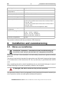
2. Installation and commissioning
2.1. Notes on installation
Installation, inspection, commissioning and troubleshooting of
the device must only be carried out by a competent electrician.
Disconnect all lines to be assembled, and take safety precautions against accidental
switch-on.
The device is exclusively intended for appropriate use. With each inappropriate change
or non-observance of the instructions for use, any warranty or guarantee claim will be
void.
After unpacking the device, check immediately for any mechanical damages. In case of
transport damage, this must immediately notified to the supplier.
If damaged, the device must not be put into operation.
If an operation without risk may supposedly not be guaranteed, the device must be put
out of operation and be secured against accidental operation.
Heating rain sensor approx. 1.2 W
Measurement range
temperature
-40…+80°C
Resolution (temperature) 0.1°C
Accuracy (temperature) ±1.5°C at -25…+80°C
Measurement range wind 0…35 m/s
Resolution (wind) 0,1 m/s
Accuracy (wind) at ambient temperature -20…+50°C:
±22% of the measurement value when incident flow is
from 45…315°
±15% of the measurement value when incident flow is
from 90…270°
(Frontal incident flow corresponds to 180°)
Measurement range
brightness
0…99 000 lux
Resolution (brightness) 1 lux at 0…120 lux
2 lux at 121…1 046 lux
63 lux at 1 047…52 363 lux
423 lux at 52 364…99 000 lux
Accuracy (brightness) ±35%

EN 6 Installation and commissioning
SHOWEAGPS Weather Station • Version: 03.05.2019 • Technical changes reserved. Errors reserved.
The device must only be operated as stationary system, i.e. only in a fitted state and
after completion of all installation and start-up works, and only in the environment in-
tended for this purpose.
Carlo Gavazzi does not assume any liability for changes in standards after publication
of this instruction manual.
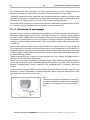
2.1.1. Installation position
Choose an installation position in the building where wind, rain and sun can be meas-
ured unhindered by the sensors. The weather station must not be installed underneath
any structural parts from which water can still drip onto the rain sensor after it has
stopped raining or snowing. The weather station must not be shaded by anything,
such as building structures or trees.
At least 60 cm of clearance must be left all round the weather station. This facilitates
correct wind speed measurement without eddies. The distance concurrently prevents
spray (raindrops hitting the device) or snow (snow penetration) from impairing the
measurement. It also does not allow birds to bite it.
Please take note that an extended awning does not shade the device from sun and
wind.
Temperature measurements can also be affected by external influences such as by
warming or cooling of the building structure on which the sensor is mounted, (sun-
light, heating or cold water pipes).
Magnetic fields, transmitters and interfering fields from electricity consumers (e.g. flu-
orescent lamps, neon signs, switched-mode power supplies etc.) can interfere with or
even cut out reception of the GPS signal.
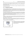
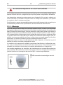
Fig. 1
There must be at least 60 cm of space below,
to the sides and in front of the weather station
left from other elements (structures, con-
struction parts, etc.).
60 cm

EN 7 Installation and commissioning
SHOWEAGPS Weather Station • Version: 03.05.2019 • Technical changes reserved. Errors reserved.
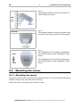
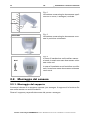
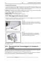
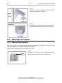
2.2. Mounting the sensor
2.2.1. Attaching the mount
The sensor comes with a combination wall/pole mount. The mount comes adhered by
adhesive strips to the rear side of the housing.
Fasten the mount vertically onto the wall or pole.
Fig. 2
The weather station must be mounted on a
vertical wall (or a pole).
Wall
or
pole
Fig. 3
The weather station must be mounted in the
horizontal transverse direction (horizontally).
Horizontal
Fig. 4
For installation in the northern hemisphere,
the weather station must be aligned to face
south.
For installation in the southern hemisphere,
the weather station must be aligned to face
north.
North
South

EN 8 Installation and commissioning
SHOWEAGPS Weather Station • Version: 03.05.2019 • Technical changes reserved. Errors reserved.
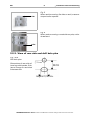
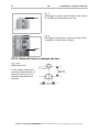
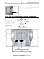
2.2.2. View of rear side and drill hole plan
Fig. 5
When wall mounting: flat side on wall, crescent-
shaped collar upward.
Collar
Fig. 6
When pole mounting: curved side on pole, collar
downward.
Collar
Langloch 7,5 x 5 mm
Fig. 7 a+b
Drill hole plan
Dimensions of rear side of
housing with bracket. Sub-
ject to change for technical
enhancement.

EN 9 Installation and commissioning
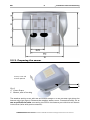
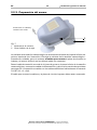
2.2.3. Preparing the sensor
The weather station cover with the rain sensor snaps in on the left and right along the
bottom edge (see figure). Remove the weather station cover. Proceed carefully, so as
not to pull off the wire connecting the PCB in the bottom part with the rain sensor
in the cover (wire with push-connector).
SHOWEAGPS Weather Station • Version: 03.05.2019 • Technical changes reserved. Errors reserved.
Fig. 8
1) Cover Snaps
2 Bottom part of housing
1
2
Unsnap cover and
remove upwards

EN 10 Installation and commissioning
SHOWEAGPS Weather Station • Version: 03.05.2019 • Technical changes reserved. Errors reserved.
Push the connecting cable through the rubber seal on the bottom of the weather sta-
tion and connect the power and bus cables to the terminals provided for this purpose.
The connection is by typical telephone cable (J-Y(ST)Y 2 × 2 × 0.8).
The connection cable must be plugged in between the cover and circuit board.
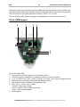
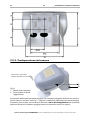
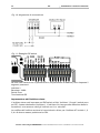
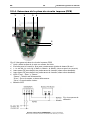
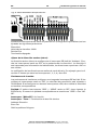
2.2.4. PCB Layout
Fig. 9: Overview PCB
1) Connection to the rain sensor in the housing cover
2) Connecting plug, suitable for massive conductors of up to 0.8 mm²
3) 1
: 12..40 V DC (12..28 V AC); 2: GND; A: RS485+; B: RS485- (see connection diagram below)
4) DIP switch for interface parameters (see detailed view)
5) DIP switch for slave address (see detailed view)
6) LED “Com”, “Error” and “Power”
„Power“: operating voltage
„Error“: sensor error or erroneous data
„Com“: bus communication
7) GPS module
1
5
2
3 4
6

EN 11 Installation and commissioning
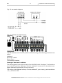
If all DIP switches are in the OFF position (default setting), the following parameters are
active:
Address: 1
Baud rate: 19,200
Parity: Even
Termination: Disabled
Setting of the slave’s address:
The slave address is set with the help of the 8-bit DIP switch “Address”. If all switches
are in the OFF position, Address
1 is active. Address 0 is reserved for broadcast mes-
sages; addresses greater than 247 are not valid.
The coding of the address is binary. For the address 47, you must e.g. set the switches
1, 2, 3, 4 and 6 to ON.
Fig. 11: detailed view DIP switches
SHOWEAGPS Weather Station • Version: 03.05.2019 • Technical changes reserved. Errors reserved.
Fig. 10: connection diagram

EN 12 Installation and commissioning
Fig. 12
Make sure the cover and bottom part are
properly snapped together! This picture is
looking at the closed sensor from under-
neath.
Fastening
SHOWEAGPS Weather Station • Version: 03.05.2019 • Technical changes reserved. Errors reserved.
Close the housing by putting the cover back over the bottom part. The cover must snap
in on the left and right with a definite “click”.
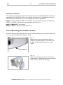
2.2.5. Mounting the weather station
Fig. 13
Push the housing from above into the fas-
tened mount. The bumps on the mount must
snap into the rails in the housing.
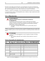
Interface parameters:
The interface parameters are set with the help of the second 8-bit DIP switch. If the first
4 switches are in the OFF position, the transfer rate amounts to 19,200 bauds. If one of
these switches is set to ON, the corresponding baud rate is applicable.
Parity: If
the two switches “ODD” and “NONE” are set to OFF, the parity is EVEN. Only
“ODD” or “NONE” activates the corresponding parity control.
Switch “Mobu EE”: no function.
Switch “Term.”: bus termination 124 ohms

EN 13 Transfer protocol
SHOWEAGPS Weather Station • Version: 03.05.2019 • Technical changes reserved. Errors reserved.
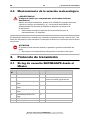
WARNING!
Risk of injury caused by components moved automatically!
The automatic control can start system components and place people in
danger (e.g. moving windows/awnings if a rain/wind alarm has been
triggered while cleaning).
• Always isolate the device from the mains for servicing and cleaning.
The device must regularly be checked for dirt twice a year and cleaned if necessary. In
case of severe dirt, the sensor may not work properly anymore.
ATTENTION
The device can be damaged if water penetrates the housing.
• Do not clean with high pressure cleaners or steam jets.
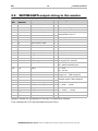
3. Transfer protocol
3.1. SHOWEAGPS request string from the master
Byte
No.
Variable Meaning
0 Slave address xx
1 Command 04H Read Input Registers
2 Start address High Byte xx
3 Start address Low Byte xx
4 Number of words High Byte xx
5 Number of words Low Byte xx
6 CRC Low Byte xx
7 CRC High Byte xx
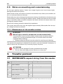
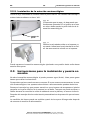
2.3. Notes
on mounting and commissioning
Do not open weather station if water (rain) might ingress: even some drops might
damage the electronic system.
Observe the correct connections. Incorrect connections may destroy the weather sta-
tion or connected electronic devices.
Please take care not to damage the temperature sensor (small blank at the bottom part
of the housing.) when mounting the weather station. Please also take care not to break
away or bend the cable connection between the blank and the rain sensor when con-
necting the weather station.
Remove all existing protection labels after installation.
The correct wind value may only be supplied approximately 60 seconds after the sup-
ply voltage has been connected.
2.3.1. Maintenance of the weather station

EN 14 Transfer protocol
SHOWEAGPS Weather Station • Version: 03.05.2019 • Technical changes reserved. Errors reserved.
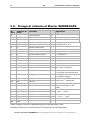
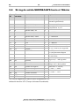
Negative values are represented in the two’s complement notation.
Time indicated as: UTC (Coordinated Universal Time).
8 5 Sun sensor, west L 1...99 Kilolux
9 6 Sun sensor, east H
10 7 Sun sensor, east L 1...99 Kilolux
11 8 Light H 0...999 Lux
12 9 Light L 0...999 Lux
13 10 Wind H Value/10 gives wind speed in m/
s (metres per second)
14 11 Wind L
15 12 GPS / RTC H 1 = GPS;
0 = quartz clock 50 ppm
16 13 Rain L 1 = rain;
0 = no rain
29 26 Azimuth H Value/10 = sun position;
angle 0.0 ... 359.9 degrees
30 27 Azimuth L
31 28 Elevation H Value/10 = sun position;
height range +/-90.0 degrees
32 29 Elevation L
33 30 Degree of longitude H Value/100 +/- xxx.xx°;
+ = east / - = west
34 31 Degree of longitude L
35 32 Degree of latitude H Value/100 +/- xxx.xx°;
+ = north / - = south
36 33 Degree of latitude L
37 CRC L
38 CRC H
3.2. SHOWEAGPS output string to the master
Byte
No.
Start
address
Variable Meaning
0 Slave address xx
1 Command 04H Read Input Registers
2 Number of bytes xx Master request * 2
3 0 Outdoor temperature H with sign, value/10 =
temperature xx.x °C
4 1 Outdoor temperature L
5 2 Sun sensor, south H
6 3 Sun sensor, south L 1...99 Kilolux
7 4 Sun sensor, west H

SHOWEAGPS
Stazione meteorologica per Modbus
Dati tecnici ed avvertenze per l'installazione
IT
www.gavazziautomation.com

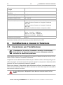
IT 16 Descrizione
stazione meteorologica SHOWEAGPS • Livello: 03.05.2019 • Con riserva di modifiche e correzioni tecniche.
1. Descrizione
La stazione meteorologica SHOWEAGPS rileva i dati come la temperatura, la ve-
locità del vento e la luminosità (sole ad est, sud, ovest), nonché le precipitazioni.
La SHOWEAGPS riceve, mediante un ricevitore GPS, il Tempo Coordinato Universale
(UTC) e le coordinate locali. Viene calcolato e reso disponibile anche l'angolo di dire-
zione (azimut) e l'altitudine solare (elevazione).
La trasmissione dei dati avviene di norma su richiesta del Master Modbus, tramite il
collegamento RS485 a 2 fili. La stazione meteo permette altrettanto la comunicazione
attraverso RS485 con PC.
La stazione meteo dispone di quattro connessioni e la trasmissione dei dati avviene sui
morsetti A e B. A questo punto trova la sua applicazione un IC, in grado di gestire su
un bus fino a 128 utenze (TI SN65LBC184D).
Funzioni:
• Rilevazione di
luminosità con tre s
ensori indipendenti per Est, Sud ed Ovest.
Rilevamento
crepuscolo con filtri speciali
• Misurazione vento: La misurazione dell'intensità del vento avviene
elettronicamente ed è quindi silenziosa ed affidabile, anche in caso di grandine,
neve e temperature basse sotto zero. Dalla stazione meteo vengono percepite
anche eventuali trombe d'aria e correnti ascensionali.
• Misura della temperatura
• Sensore precipitazioni risc
aldato (1,2 Watt): Nessuna misurazione errata
dovuta a rugiada o nebbia, asciugatura rapida al termine della precipitazione
• Ricevitore GPS integrato. Emissione dell'orario universale coordinato (UTC),
della posizione geografica (longitudine e latitudine) e della posizione del sole
(azimut,
elevazione)
1.1. Dati tecnici
Alloggiamento Plastica
Colore Bianco / translucido
Montaggio A parete
Grado di protezione IP 44
Dimensioni ca. 96 × 77 × 118 (L × A × P, mm)
Peso ca. 160 g
Temperatura ambiente Funzionamento -30 … +50°C, Stoccaggio -30 … +70°C
Tensione di esercizio
12...40 V CC (12...28 V CA)
Sezione del cavo filo rigido fino a 0,8 mm²
Corrente max. 80 mA, ondulazione residua (ripple) 10%
Trasmissione dati RS485 a 2 fili
Protocollo Modbus RTU
ATTENZIONE!
Accertarsi che i collegamenti siano corretti! Il modulo di interfaccia viene
danneggiato, se l’alimentazione viene collegata ai morsetti sbagliati.
• Collegare l’alimentazione solo nei terminali 1 e 2.
• Utilizzare i cavi dati A e B esclusivamente per il Modbus.

IT 17 Installazione e messa in funzione
stazione meteorologica SHOWEAGPS • Livello: 03.05.2019 • Con riserva di modifiche e correzioni tecniche.
Il prodotto risulta conforme a quanto previsto dalle direttive UE.0
2. Installazione e messa in funzione
2.1. Avvertenze per l'installazione
L'installazione, la verifica, la messa in servizio e la risoluzione
dei problemi del dispositivo devono essere effettuate esclusiva-
mente da un elettricista qualificato.
Isolare dalla tensione tutte le condotte da montare ed adottare tutte le misure di sicu-
rezza contro la messa in tensione involontaria.
I dispositivi sono realizzati esclusivamente per l'utilizzo consono allo scopo. Ogni mo-
difica impropria od inosservanza del manuale operativo comporta la decadenza della
garanzia e di tutte le eventuali pretese di garanzia.
Dopo aver rimosso il dispositivo dalla confezione verificare immediatamente la pre-
senza di eventuali danni meccanici. Se si riscontra un danno da trasporto è necessario
comunicarlo subito al fornitore.
In caso di guasto i dispositivi non devono essere messi in fun-
zione.
Riscaldamento sensore
pioggia
ca. 1,2 W
Campo di misurazione tem-
peratura
-40 ... +80°C
Risoluzione (Temperatura) 0,1°C
Precisione (Temperatura) ± 1,5°C a -25 ... +80°C
Campo di misura vento 0 ... 35 m/s
Risoluzione (Vento) 0,1 m/s
Precisione (Vento) con temperatura ambiente -20…+50°C:
±22% del valore rilevato con l’angolo d’incidenza
45…315°
±15% del valore rilevato con l’angolo d’incidenza
90…270°
(angolo d’incidenza frontale corrisponde a 180°)
Campo di misura luminosità 0 ... 99.000 Lux
Risoluzione (Luminosità) 1 Lux con 0 … 120 Lux
2 Lux con 121 … 1.046 Lux
63 Lux con 1.047 … 52.363 Lux
423 Lux con 52.364 … 99.000 Lux
Precisione (Luminosità) ±35 %

IT 18 Installazione e messa in funzione
stazione meteorologica SHOWEAGPS • Livello: 03.05.2019 • Con riserva di modifiche e correzioni tecniche.
Se si accerta che non è garantito un funzionamento sicuro, porre il dispositivo fuori
servizio e metterlo in sicurezza per evitare la messa in funzione involontaria.
I dispositivi possono essere impiegati solo previa installazione stabile, cioè solo come
elementi incorporati, a condizione che siano stati completati tutti i procedimenti d’in-
stallazione e di messa in servizio e solo al fine e nell’ambiente previsto.
La società Carlo Gavazzi non risponde di eventuali modifiche o aggiornamenti norma-
tivi, successivi alla pubblicazione del presente manuale operativo.
2.1.1. Posizione di montaggio
Scegliere una posizione d'installazione sull'edificio tale da permettere la rilevazione in-
disturbata della pioggia, vento e sole, da parte dei sensori. La stazione meteorologica
non deve essere posizionata sotto elementi costruttivi che permettano gocciolamento
sul sensore di precipitazioni, anche a pioggia o nevicata terminata. La stazione meteo-
rologica non deve essere posizionata in una zona d’ombra, data da elementi costruttivi
o
da
alberi.
Attorno alla stazione meteo deve essere lasciato uno spazio libero minimo di 60 cm.
Ciò consentirà un corretto rilevamento del vento, senza turbolenze di aria. Inoltre con
questa distanza si eviterà che il rilevamento venga compromesso da spruzzi (rimbalza-
re della pioggia) o dalla neve (innevamento). Vengono contemporaneamente prevenu-
te le beccate degli uccelli.
Prestare attenzione che la tenda da sole estratta non crei l'ombra sull'apparecchio e
che esso non sia collocato sottovento.
Anche la misura della temperatura potrebbe subire delle alterazioni da agenti esterni,
ad es. dal riscaldamento o raffreddamento dell'elemento sul quale viene montato il
sensore (irraggiamento solare, tubazione del riscaldamento o condotta dell'acqua
fredda).
La ricezione del segnale GPS può essere disturbata o impedita da campi magnetici, tra-
smettitori o campi interferenti di utenze elettriche (ad es. lampade fluorescenti, inse-
gne luminose, convertitori cc-cc, ecc.).
Fig. 1
La stazione meteo deve disporre di uno spa-
zio libero sottostante, adiacente e frontale di
almeno 60 cm (elementi o parti costruttive,
ecc.).
60 cm

IT 19 Installazione e messa in funzione
stazione meteorologica SHOWEAGPS • Livello: 03.05.2019 • Con riserva di modifiche e correzioni tecniche.
2.2. Montaggio del sensore
2.2.1. Montaggio del supporto
Il sensore è dotato di un supporto a parete / per sostegno. Il supporto è in fornitura fis-
sato sulla scatola con striscie adesive.
Fissare il supporto perpendicolarmente alla parete o sostegno.
Fig. 2
La stazione meteorologica deve essere appli-
cata su un muro (o sostegno) verticale.
Muro
o
sostegno
Fig. 3
La stazione meteorologica deve essere mon-
tata in posizione orizzontale.
Orizzontale
Fig. 4
In caso di installazione nell'emisfero setten-
trionale, la stazione meteo deve essere orien-
tata verso sud.
In caso di installazione nell'emisfero meridio-
nale, la stazione meteo deve essere orientata
verso nord.
Nord
Sud

IT 20 Installazione e messa in funzione
stazione meteorologica SHOWEAGPS • Livello: 03.05.2019 • Con riserva di modifiche e correzioni tecniche.
2.2.2. Vista del retro e schema dei fori
Fig. 5
Montaggio a parete: la parte piana verso la pare-
te, la staffa a mezzaluna verso l’alto.
Staffa
Fig. 6
Montaggio su sostegno: la parte arcuata verso il
sostegno, la staffa verso il basso.
Staffa
Asola 7,5 x 5 mm
Fig. 7 a+b
Disposizione fori.
Le dimensioni della parte
posteriore della scatola con
supporto, misure in mm.
Possibili differenziazioni
tecniche.
La pagina si sta caricando...
La pagina si sta caricando...
La pagina si sta caricando...
La pagina si sta caricando...
La pagina si sta caricando...
La pagina si sta caricando...
La pagina si sta caricando...
La pagina si sta caricando...
La pagina si sta caricando...
La pagina si sta caricando...
La pagina si sta caricando...
La pagina si sta caricando...
La pagina si sta caricando...
La pagina si sta caricando...
La pagina si sta caricando...
La pagina si sta caricando...
La pagina si sta caricando...
La pagina si sta caricando...
-
 1
1
-
 2
2
-
 3
3
-
 4
4
-
 5
5
-
 6
6
-
 7
7
-
 8
8
-
 9
9
-
 10
10
-
 11
11
-
 12
12
-
 13
13
-
 14
14
-
 15
15
-
 16
16
-
 17
17
-
 18
18
-
 19
19
-
 20
20
-
 21
21
-
 22
22
-
 23
23
-
 24
24
-
 25
25
-
 26
26
-
 27
27
-
 28
28
-
 29
29
-
 30
30
-
 31
31
-
 32
32
-
 33
33
-
 34
34
-
 35
35
-
 36
36
-
 37
37
-
 38
38


CARLO GAVAZZI SHOWEAGPS Guida d'installazione
- Tipo
- Guida d'installazione
in altre lingue
Altri documenti
-
elsner elektronik TH-AP Modbus Technical Reference
-
TFA Dostmann Mondo Manuale utente
-
Auriol 4-LD4868 Usage And Safety Instructions
-
Bresser 7001022 Manuale del proprietario
-
-
TFA 35.1103 - Meteotime Easy Manuale del proprietario
-
-
-
Davis Instruments 6161 Manuale del proprietario
-