GIOTTO BT A 30-60S U
GIOTTO BT A 30-60 U
GIOTTO BT A 30-60S U
GIOTTO BT A 30-60 U
D812433 00100_05 26-07-17
AUTOMATISMO ELETTROMECCANICO PER BARRIERA VEICOLARE
ELECTROMECHANICAL CONTROL DEVICE FOR VEHICULAR BARRIERS
AUTOMATISME ELECTROMECANIQUE POUR BARRIERE POUR VÉHICULES
ELEKTROMECHANISCHER ANTRIEB FÜR FAHRZEUGSCHRANKEN
AUTOMATISMOS ELECTROMECANICOS PARA BARRÉRAS VEHICULAR
ELEKTROMECHANISCH AUTOMATISERINGSSYSTEEM VOOR SLAGBOOM
ISTRUZIONI D’USO E DI INSTALLAZIONE
INSTALLATION AND USER’S MANUAL
INSTRUCTIONS D’UTILISATION ET D’INSTALLATION
INSTALLATIONS-UND GEBRAUCHSANLEITUNG
INSTRUCCIONES DE USO Y DE INSTALACION
GEBRUIKS- EN INSTALLATIEAANWIJZINGEN
Attenzione! Leggere attentamente le “Avvertenze” all’interno! Caution! Read “Warnings” inside carefully! Attention! Veuillez lire attentivement les Avertissements qui se trouvent à l’intérieur!
Achtung! Bitte lesen Sie aufmerksam die „Hinweise“ im Inneren! ¡Atención¡ Leer atentamente las “Advertencias”en el interior! Let op! Lees de “Waarschuwingen” aan de binnenkant zorgvuldig!

AVVERTENZE PER L’UTILIZZATORE ( I )
Lingua originale
ATTENZIONE! Importanti istruzioni di sicurezza.
Leggere e seguire attentamente le Avvertenze
e le Istruzioni che accompagnano il prodotto
poiché un uso improprio può causare danni a
persone, animali o cose. Conservare le istruzioni
per consultazioni future e trasmetterle ad even
-
tuali subentranti nell’uso dell’impianto.
Questo prodotto dovrà essere destinato solo
all’uso per il quale è stato espressamente insta-
llato. Ogni altro uso è da considerarsi improprio
e quindi pericoloso. Il costruttore non può essere
considerato responsabile per eventuali danni
causati da usi impropri, erronei e irragionevoli.
SICUREZZA GENERALE
Nel ringraziarVi per la preferenza accordata a questo
prodotto, la Ditta è certa che da esso otterrete le
prestazioni necessarie al Vostro uso.
Questo prodotto risponde alle norme riconosciute
della tecnica e della disposizioni relative alla si
-
curezza se correttamente installato da personale
qualicato ed esperto (installatore professionale).
L’automazione, se installata ed utilizzata corretta-
mente, soddisfa gli standard di sicurezza nell’uso.
Tuttavia è opportuno osservare alcune regole di
comportamento per evitare inconvenienti acci-
dentali:
- Tenere bambini, persone e cose fuori dal raggio
d’azione dell’automazione, in particolare durante
il movimento.
- Non permettere a bambini di giocare o sostare nel
raggio di azione dell’automazione.
- L’apparecchio può essere utilizzato da bambini di
età non inferiore a 8 anni e da persone con ridot
-
te capacità siche, sensoriali o mentali, o prive di
esperienza o della necessaria conoscenza, purché
sotto sorveglianza oppure dopo che le stesse
abbiano ricevuto istruzioni relative all’uso sicuro
dell’apparecchio e alla comprensione dei pericoli
ad esso inerenti. I bambini non devono giocare con
l’apparecchio. La pulizia e la manutenzione desti-
nata ad essere eettuata dall’utilizzatore non deve
essere eettuata da bambini senza sorveglianza.
- I bambini devono essere sorvegliati per sincerarsi
che non giochino con l’apparecchio. Non permet-
tere ai bambini di giocare con i controlli ssi. Tenere
i telecomandi lontani dai bambini.
-
Evitare di operare in prossimità delle cerniere o organi
meccanici in movimento.
-
Non contrastare il movimento dell’anta e non ten-
tare di aprire manualmente la porta se non è stato
sbloccato l’attuatore con l’apposito sblocco.
- Non entrare nel raggio di azione della porta o
cancello motorizzati durante il loro movimento.
- Non lasciare radiocomandi o altri dispositivi di
comando alla portata dei bambini onde evitare
azionamenti involontari.
- L’attivazione dello sblocco manuale potrebbe
causare movimenti incontrollati della porta se in
presenza di guasti meccanici o di condizioni di
squilibrio.
- In caso di apritapparelle: sorvegliare la tapparella
in movimento e tenere lontano le persone nché
non è completamente chiusa. Porre cura quando si
aziona lo sblocco se presente, poiché una tapparella
aperta potrebbe cadere rapidamente in presenza
di usura o rotture.
-
La rottura o l’usura di organi meccanici della porta
(parte guidata), quali ad esempio cavi, molle, sup-
porti, cardini, guide.. potrebbe generare pericoli. Far
controllare periodicamente l’impianto da personale
qualicato ed esperto (installatore professionale)
secondo quanto indicato dall’installatore o dal
costruttore della porta.
- Per ogni operazione di pulizia esterna, togliere
l’alimentazione di rete.
- Tenere pulite le ottiche delle fotocellule ed i dispo-
sitivi di segnalazione luminosa. Controllare che rami
ed arbusti non disturbino i dispositivi di sicurezza.
- Non utilizzare l’automatismo se necessita di
interventi di riparazione. In caso di guasto o di
malfunzionamento dell’automazione, togliere
l’alimentazione di rete sull’automazione, astenersi
da qualsiasi tentativo di riparazione o intervento
diretto e rivolgersi solo a personale qualicato ed
esperto (installatore professionale) per la neces
-
saria riparazione o manutenzione. Per consentire
l’accesso, attivare lo sblocco di emergenza (se
presente).
-
Per qualsiasi intervento diretto sull’automazione o
sull’impianto non previsto dal presente manuale,
avvalersi di personale qualicato ed esperto (insta-
llatore professionale).
- Con frequenza almeno annuale far verifi-
care l’integrità e il corretto funzionamento
dell’automazione da personale qualificato ed
esperto (installatore professionale), in particolare
di tutti i dispositivi di sicurezza.
- Gli interventi d’installazione, manutenzione e
riparazione devono essere documentati e la
relativa documentazione tenuta a disposizione
dell’utilizzatore.
- Il mancato rispetto di quanto sopra può creare
situazioni di pericolo.
Tutto quello che non è espressamente previsto
nel manuale d’uso, non è permesso. ll buon fun-
zionamento dell’operatore è garantito solo se ven-
gono rispettate le prescrizioni riportate in questo
manuale. La Ditta non risponde dei danni causati
dall’inosservanza delle indicazioni riportate in questo
manuale.
Lasciando inalterate le caratteristiche essenziali del
prodotto, la Ditta si riserva di apportare in qualunque
momento le modiche che essa ritiene convenienti
per migliorare tecnicamente, costruttivamente e
commercialmente il prodotto, senza impegnarsi ad
aggiornare la presente pubblicazione.
USER WARNINGS (GB)
WARNING! Important safety instructions. Ca-
D812231_05
refully read and comply with the Warnings and
Instructions that come with the product as impro-
per use can cause injury to people and animals
and damage to property. Keep the instructions
for future reference and hand them on to any
new users.
This product is meant to be used only for the
purpose for which it was explicitly installed.
Any other use constitutes improper use and,
consequently, is hazardous. The manufacturer
cannot be held liable for any damage as a result
of improper, incorrect or unreasonable use.
GENERAL SAFETY
Thank you for choosing this product. The Firm is
condent that its performance will meet your ope
-
rating needs.
This product meets recognized technical standards
and complies with safety provisions when installed
correctly by qualied, expert personnel (professional
installer).
If installed and used correctly, the automated system
will meet operating safety standards. Nonetheless,
it is advisable to observe certain rules of behaviour
so that accidental problems can be avoided:
- Keep adults, children and property out of range of
the automated system, especially while it is moving.
- Do not allow children to play or stand within range
of the automated system.
- The unit can be used by children over 8 years old
and by people with reduced physical, sensory or
mental capabilities or with no experience or neces
-
sary knowledge on condition they are supervised
or trained about the safe use of the equipment
and understand the risks involved. Children must
not play with the unit. Cleaning and maintenance
must not be performed by unsupervised children.
- Children must be supervised to ensure they do not
play with the device. Do not allow children to play
with the xed controls. Keep remote controls out
of reach of children.
- Do not work near hinges or moving mechanical
parts.
- Do not hinder the leaf’s movement and do not
attempt to open the door manually unless the ac
-
tuator has been released with the relevant release
knob.
- Keep out of range of the motorized door or gate
while they are moving.
- Keep remote controls or other control devices out
of reach of children in order to avoid the automated
system being operated inadvertently.
- The manual release’s activation could result in un
-
controlled door movements if there are mechanical
faults or loss of balance.
- When using roller shutter openers: keep an eye
on the roller shutter while it is moving and keep
people away until it has closed completely. Exercise
care when activating the release, if such a device
is tted, as an open shutter could drop quickly in
the event of wear or breakage.
- The breakage or wear of any mechanical parts of
the door (operated part), such as cables, springs,
supports, hinges, guides…, may generate a hazard.
Have the system checked by qualied, expert per
-
sonnel (professional installer) at regular intervals
according to the instructions issued by the installer
or manufacturer of the door.
- When cleaning the outside, always cut o mains
power.
- Keep the photocells’ optics and illuminating in
-
dicator devices clean. Check that no branches or
shrubs interfere with the safety devices.
- Do not use the automated system if it is in need of
repair. In the event the automated system breaks
down or malfunctions, cut o mains power to the
system; do not attempt to repair or perform any
other work to rectify the fault yourself and instead
call in qualied, expert personnel (professional
installer) to perform the necessary repairs or main
-
tenance. To allow access, activate the emergency
release (where tted).
- If any part of the automated system requires direct
work of any kind that is not contemplated herein,
employ the services of qualied, expert personnel
(professional installer).
- At least once a year, have the automated system, and
especially all safety devices, checked by qualied,
expert personnel (professional installer) to make
sure that it is undamaged and working properly.
-
A record must be made of any installation, mainte-
nance and repair work and the relevant documenta-
tion kept and made available to the user on request.
- Failure to comply with the above may result in
hazardous situations.
Anything that is not explicitly provided for in the
user guide is not allowed. The operator’s proper
operation can only be guaranteed if the instruc
-
tions given herein are complied with. The Firm
shall not be answerable for damage caused by
failure to comply with the instructions featured
herein.
While we will not alter the product’s essential
features, the Firm reserves the right, at any time,
to make those changes deemed opportune to
improve the product from a technical, design or
commercial point of view, and will not be required
to update this publication accordingly.
AVERTISSEMENTS POUR L’UTILISATEUR (F)
ATTENTION ! Instructions de sécurité importantes.
Veuillez lire et suivre attentivement tous les aver-
tissements et toutes les instructions fournis avec le
produit sachant qu’un usage incorrect peut provo-
quer des préjudices aux personnes, aux animaux ou
aux biens. Veuillez conserver les instructions pour
d’ultérieures consultations et pour les transmettre
aux propriétaires futurs éventuels.
Cet appareil ne peut être destiné qu’à l’usage
pour lequel il a été expressément installé. Tout
autre usage sera considéré comme impropre et
donc dangereux. Le fabricant ne sera en aucun
cas considéré comme responsable des préjudices
dus à un usage impropre, erroné ou déraisonné.
SECURITE GÉNÉRALE
D812231_05
2 - GIOTTO BT A 30-60 S U / GIOTTO BT A 30-60 U
D812433 00100_05

AVVERTENZE PER L’UTILIZZATORE ( I )
Lingua originale
ATTENZIONE! Importanti istruzioni di sicurezza.
Leggere e seguire attentamente le Avvertenze
e le Istruzioni che accompagnano il prodotto
poiché un uso improprio può causare danni a
persone, animali o cose. Conservare le istruzioni
per consultazioni future e trasmetterle ad even
-
tuali subentranti nell’uso dell’impianto.
Questo prodotto dovrà essere destinato solo
all’uso per il quale è stato espressamente insta-
llato. Ogni altro uso è da considerarsi improprio
e quindi pericoloso. Il costruttore non può essere
considerato responsabile per eventuali danni
causati da usi impropri, erronei e irragionevoli.
SICUREZZA GENERALE
Nel ringraziarVi per la preferenza accordata a questo
prodotto, la Ditta è certa che da esso otterrete le
prestazioni necessarie al Vostro uso.
Questo prodotto risponde alle norme riconosciute
della tecnica e della disposizioni relative alla si
-
curezza se correttamente installato da personale
qualicato ed esperto (installatore professionale).
L’automazione, se installata ed utilizzata corretta-
mente, soddisfa gli standard di sicurezza nell’uso.
Tuttavia è opportuno osservare alcune regole di
comportamento per evitare inconvenienti acci-
dentali:
- Tenere bambini, persone e cose fuori dal raggio
d’azione dell’automazione, in particolare durante
il movimento.
- Non permettere a bambini di giocare o sostare nel
raggio di azione dell’automazione.
- L’apparecchio può essere utilizzato da bambini di
età non inferiore a 8 anni e da persone con ridot
-
te capacità siche, sensoriali o mentali, o prive di
esperienza o della necessaria conoscenza, purché
sotto sorveglianza oppure dopo che le stesse
abbiano ricevuto istruzioni relative all’uso sicuro
dell’apparecchio e alla comprensione dei pericoli
ad esso inerenti. I bambini non devono giocare con
l’apparecchio. La pulizia e la manutenzione desti-
nata ad essere eettuata dall’utilizzatore non deve
essere eettuata da bambini senza sorveglianza.
- I bambini devono essere sorvegliati per sincerarsi
che non giochino con l’apparecchio. Non permet-
tere ai bambini di giocare con i controlli ssi. Tenere
i telecomandi lontani dai bambini.
-
Evitare di operare in prossimità delle cerniere o organi
meccanici in movimento.
-
Non contrastare il movimento dell’anta e non ten-
tare di aprire manualmente la porta se non è stato
sbloccato l’attuatore con l’apposito sblocco.
- Non entrare nel raggio di azione della porta o
cancello motorizzati durante il loro movimento.
- Non lasciare radiocomandi o altri dispositivi di
comando alla portata dei bambini onde evitare
azionamenti involontari.
- L’attivazione dello sblocco manuale potrebbe
causare movimenti incontrollati della porta se in
presenza di guasti meccanici o di condizioni di
squilibrio.
- In caso di apritapparelle: sorvegliare la tapparella
in movimento e tenere lontano le persone nché
non è completamente chiusa. Porre cura quando si
aziona lo sblocco se presente, poiché una tapparella
aperta potrebbe cadere rapidamente in presenza
di usura o rotture.
-
La rottura o l’usura di organi meccanici della porta
(parte guidata), quali ad esempio cavi, molle, sup-
porti, cardini, guide.. potrebbe generare pericoli. Far
controllare periodicamente l’impianto da personale
qualicato ed esperto (installatore professionale)
secondo quanto indicato dall’installatore o dal
costruttore della porta.
- Per ogni operazione di pulizia esterna, togliere
l’alimentazione di rete.
- Tenere pulite le ottiche delle fotocellule ed i dispo-
sitivi di segnalazione luminosa. Controllare che rami
ed arbusti non disturbino i dispositivi di sicurezza.
- Non utilizzare l’automatismo se necessita di
interventi di riparazione. In caso di guasto o di
malfunzionamento dell’automazione, togliere
l’alimentazione di rete sull’automazione, astenersi
da qualsiasi tentativo di riparazione o intervento
diretto e rivolgersi solo a personale qualicato ed
esperto (installatore professionale) per la neces
-
saria riparazione o manutenzione. Per consentire
l’accesso, attivare lo sblocco di emergenza (se
presente).
-
Per qualsiasi intervento diretto sull’automazione o
sull’impianto non previsto dal presente manuale,
avvalersi di personale qualicato ed esperto (insta-
llatore professionale).
- Con frequenza almeno annuale far verifi-
care l’integrità e il corretto funzionamento
dell’automazione da personale qualificato ed
esperto (installatore professionale), in particolare
di tutti i dispositivi di sicurezza.
- Gli interventi d’installazione, manutenzione e
riparazione devono essere documentati e la
relativa documentazione tenuta a disposizione
dell’utilizzatore.
- Il mancato rispetto di quanto sopra può creare
situazioni di pericolo.
Tutto quello che non è espressamente previsto
nel manuale d’uso, non è permesso. ll buon fun-
zionamento dell’operatore è garantito solo se ven-
gono rispettate le prescrizioni riportate in questo
manuale. La Ditta non risponde dei danni causati
dall’inosservanza delle indicazioni riportate in questo
manuale.
Lasciando inalterate le caratteristiche essenziali del
prodotto, la Ditta si riserva di apportare in qualunque
momento le modiche che essa ritiene convenienti
per migliorare tecnicamente, costruttivamente e
commercialmente il prodotto, senza impegnarsi ad
aggiornare la presente pubblicazione.
USER WARNINGS (GB)
WARNING! Important safety instructions. Ca-
D812231_05
refully read and comply with the Warnings and
Instructions that come with the product as impro-
per use can cause injury to people and animals
and damage to property. Keep the instructions
for future reference and hand them on to any
new users.
This product is meant to be used only for the
purpose for which it was explicitly installed.
Any other use constitutes improper use and,
consequently, is hazardous. The manufacturer
cannot be held liable for any damage as a result
of improper, incorrect or unreasonable use.
GENERAL SAFETY
Thank you for choosing this product. The Firm is
condent that its performance will meet your ope
-
rating needs.
This product meets recognized technical standards
and complies with safety provisions when installed
correctly by qualied, expert personnel (professional
installer).
If installed and used correctly, the automated system
will meet operating safety standards. Nonetheless,
it is advisable to observe certain rules of behaviour
so that accidental problems can be avoided:
- Keep adults, children and property out of range of
the automated system, especially while it is moving.
- Do not allow children to play or stand within range
of the automated system.
- The unit can be used by children over 8 years old
and by people with reduced physical, sensory or
mental capabilities or with no experience or neces
-
sary knowledge on condition they are supervised
or trained about the safe use of the equipment
and understand the risks involved. Children must
not play with the unit. Cleaning and maintenance
must not be performed by unsupervised children.
- Children must be supervised to ensure they do not
play with the device. Do not allow children to play
with the xed controls. Keep remote controls out
of reach of children.
- Do not work near hinges or moving mechanical
parts.
- Do not hinder the leaf’s movement and do not
attempt to open the door manually unless the ac
-
tuator has been released with the relevant release
knob.
- Keep out of range of the motorized door or gate
while they are moving.
- Keep remote controls or other control devices out
of reach of children in order to avoid the automated
system being operated inadvertently.
- The manual release’s activation could result in un
-
controlled door movements if there are mechanical
faults or loss of balance.
- When using roller shutter openers: keep an eye
on the roller shutter while it is moving and keep
people away until it has closed completely. Exercise
care when activating the release, if such a device
is tted, as an open shutter could drop quickly in
the event of wear or breakage.
- The breakage or wear of any mechanical parts of
the door (operated part), such as cables, springs,
supports, hinges, guides…, may generate a hazard.
Have the system checked by qualied, expert per
-
sonnel (professional installer) at regular intervals
according to the instructions issued by the installer
or manufacturer of the door.
- When cleaning the outside, always cut o mains
power.
- Keep the photocells’ optics and illuminating in
-
dicator devices clean. Check that no branches or
shrubs interfere with the safety devices.
- Do not use the automated system if it is in need of
repair. In the event the automated system breaks
down or malfunctions, cut o mains power to the
system; do not attempt to repair or perform any
other work to rectify the fault yourself and instead
call in qualied, expert personnel (professional
installer) to perform the necessary repairs or main
-
tenance. To allow access, activate the emergency
release (where tted).
- If any part of the automated system requires direct
work of any kind that is not contemplated herein,
employ the services of qualied, expert personnel
(professional installer).
- At least once a year, have the automated system, and
especially all safety devices, checked by qualied,
expert personnel (professional installer) to make
sure that it is undamaged and working properly.
-
A record must be made of any installation, mainte-
nance and repair work and the relevant documenta-
tion kept and made available to the user on request.
- Failure to comply with the above may result in
hazardous situations.
Anything that is not explicitly provided for in the
user guide is not allowed. The operator’s proper
operation can only be guaranteed if the instruc
-
tions given herein are complied with. The Firm
shall not be answerable for damage caused by
failure to comply with the instructions featured
herein.
While we will not alter the product’s essential
features, the Firm reserves the right, at any time,
to make those changes deemed opportune to
improve the product from a technical, design or
commercial point of view, and will not be required
to update this publication accordingly.
D812231_05
GIOTTO BT A 30-60 S U / GIOTTO BT A 30-60 U - 3
D812433 00100_05

MANUALE D’USO: MANOVRA MANUALE - USER’S MANUAL: MANUAL OPERATION-
MANUEL D’UTILISATION: MANŒUVRE MANUELLE - BEDIENUNGSANLEITUNG: MANUELLES MANÖVER-
MANUAL DE USO: ACCIONAMIENTO MANUAL - GEBRUIKSHANDLEIDING: MANUEEL MANOEUVRE
Fig. Y
8 - GIOTTO BT A 30-60 S U / GIOTTO BT A 30-60 U
D812433 00100_05

INSTALLER WARNINGS
Anything that is not explicitly provided for in the installation ma-
nual is not allowed. The operator’s proper operation can only be
guaranteed if the information given is complied with. The Firm shall
not be answerable for damage caused by failure to comply with the
instructions featured herein.
While we will not alter the product’s essential features, the Firm reserves
the right, at any time, to make those changes deemed opportune to
improve the product from a technical, design or commercial point of
view, and will not be required to update this publication accordingly.
WARNING! Important safety instructions. Carefully read and comply with
all the warnings and instructions that come with the product as incorrect
installation can cause injury to people and animals and damage to property.
The warnings and instructions give important information regarding safety,
installation, use and maintenance. Keep hold of instructions so that you can
attach them to the technical le and keep them handy for future reference.
GENERAL SAFETY
This product has been designed and built solely for the purpose indicated herein.
Uses other than those indicated herein might cause damage to the product and
create a hazard.
- The units making up the machine and its installation must meet the requirements
of the following European Directives, where applicable: 2014/30/UE, 2014/35/UE,
2006/42/UE, 2011/305/UE, 2014/53/UE and later amendments. For all countries
outside the UE, it is advisable to comply with the standards mentioned, in addi-
tion to any national standards in force, to achieve a good level of safety.
- The Manufacturer of this product (hereinafter referred to as the “Firm”) disclaims
all responsibility resulting from improper use or any use other than that for
which the product has been designed, as indicated herein, as well as for failure
to apply Good Practice in the construction of entry systems (doors, gates, etc.)
and for deformation that could occur during use.
- Installation must be carried out by qualied personnel (professional installer,
according to EN 12635), in compliance with Good Practice and current code.
- Before installing the product, make all structural changes required to produce
safety gaps and to provide protection from or isolate all crushing, shearing and
dragging hazard areas and danger zones in general in accordance with the
provisions of standards EN 12604 and 12453 or any local installation standards.
Check that the existing structure meets the necessary strength and stability
requirements.
- Before commencing installation, check the product for damage.
- The Firm is not responsible for failure to apply Good Practice in the construction
and maintenance of the doors, gates, etc. to be motorized, or for deformation
that might occur during use.
- Make sure the stated temperature range is compatible with the site in which the
automated system is due to be installed.
- Do not install this product in an explosive atmosphere: the presence of ammable
fumes or gas constitutes a serious safety hazard.
- Disconnect the electricity supply before performing any work on the system.
Also disconnect buer batteries, if any are connected.
- Before connecting the power supply, make sure the product’s ratings match the
mains ratings and that a suitable residual current circuit breaker and overcurrent
protection device have been installed upline from the electrical system. Have
the automated system’s mains power supply tted with a switch or omnipolar
thermal-magnetic circuit breaker with a contact separation that provide full
disconnection under overvoltage category III conditions.
- Make sure that upline from the mains power supply there is a residual current
circuit breaker that trips at no more than 0.03A as well as any other equipment
required by code.
- Make sure the earth system has been installed correctly: earth all the metal parts
belonging to the entry system (doors, gates, etc.) and all parts of the system
featuring an earth terminal.
- Installation must be carried out using safety devices and controls that meet
standards EN 12978 and EN 12453.
- Impact forces can be reduced by using deformable edges.
- In the event impact forces exceed the values laid down by the relevant standards,
apply electro-sensitive or pressure-sensitive devices.
- Apply all safety devices (photocells, safety edges, etc.) required to keep the
area free of impact, crushing, dragging and shearing hazards. Bear in mind the
standards and directives in force, Good Practice criteria, intended use, the instal-
lation environment, the operating logic of the system and forces generated by
the automated system.
- Apply all signs required by current code to identify hazardous areas (residual
risks). All installations must be visibly identied in compliance with the provisions
of standard EN 13241-1.
- Once installation is complete, apply a nameplate featuring the door/gate’s data.
- This product cannot be installed on leaves incorporating doors (unless the motor
can be activated only when the door is closed).
- If the automated system is installed at a height of less than 2.5 m or is accessible,
the electrical and mechanical parts must be suitably protected.
- For roller shutter automation only
1) The motor’s moving parts must be installed at a height greater than 2.5 m
above the oor or other surface from which they may be reached.
2) The gearmotor must be installed in a segregated and suitably protected space
so that it cannot be reached without the aid of tools.
- Install any xed controls in a position where they will not cause a hazard, away
from moving parts. More specically, hold-to-run controls must be positioned
within direct sight of the part being controlled and, unless they are key operated,
must be installed at a height of at least 1.5 m and in a place where they cannot
be reached by the public.
- Apply at least one warning light (ashing light) in a visible position, and also
attach a Warning sign to the structure.
- Attach a label near the operating device, in a permanent fashion, with informa-
tion on how to operate the automated system’s manual release.
- Make sure that, during operation, mechanical risks are avoided or relevant
protective measures taken and, more specically, that nothing can be banged,
crushed, caught or cut between the part being operated and surrounding parts.
- Once installation is complete, make sure the motor automation settings are
correct and that the safety and release systems are working properly.
- Only use original spare parts for any maintenance or repair work. The Firm dis-
claims all responsibility for the correct operation and safety of the automated
system if parts from other manufacturers are used.
- Do not make any modications to the automated system’s components unless
explicitly authorized by the Firm.
- Instruct the system’s user on what residual risks may be encountered, on the
control systems that have been applied and on how to open the system manu-
ally in an emergency. give the user guide to the end user.
- Dispose of packaging materials (plastic, cardboard, polystyrene, etc.) in accord-
ance with the provisions of the laws in force. Keep nylon bags and polystyrene
out of reach of children.
WIRING
WARNING! For connection to the mains power supply, use: a multicore cable with
a cross-sectional area of at least 5x1.5mm
2
or 4x1.5mm
2
when dealing with three-
phase power supplies or 3x1.5mm
2
for single-phase supplies (by way of example,
type H05RN-F cable can be used with a cross-sectional area of 4x1.5mm
2
). To con-
nect auxiliary equipment, use wires with a cross-sectional area of at least 0.5 mm
2
.
- Only use pushbuttons with a capacity of 10A-250V or more.
- Wires must be secured with additional fastening near the terminals (for example,
using cable clamps) in order to keep live parts well separated from safety extra
low voltage parts.
- During installation, the power cable must be stripped to allow the earth wire
to be connected to the relevant terminal, while leaving the live wires as short
as possible. The earth wire must be the last to be pulled taut in the event the
cable’s fastening device comes loose.
WARNING! safety extra low voltage wires must be kept physically separate from
low voltage wires.
Only qualied personnel (professional installer) should be allowed to access
live parts.
CHECKING THE AUTOMATED SYSTEM AND MAINTENANCE
Before the automated system is nally put into operation, and during maintenance
work, perform the following checks meticulously:
- Make sure all components are fastened securely.
- Check starting and stopping operations in the case of manual control.
- Check the logic for normal or personalized operation.
- For sliding gates only: check that the rack and pinion mesh correctly with 2 mm
of play along the full length of the rack; keep the track the gate slides on clean
and free of debris at all times.
- For sliding gates and doors only: make sure the gate’s running track is straight
and horizontal and that the wheels are strong enough to take the weight of the
gate.
- For cantilever sliding gates only: make sure there is no dipping or swinging
during operation.
- For swing gates only: make sure the leaves’ axis of rotation is perfectly vertical.
-For barriers only: before opening the door, the spring must be decompressed
(vertical boom).
- Check that all safety devices (photocells, safety edges, etc.) are working properly
and that the anti-crush safety device is set correctly, making sure that the force
of impact measured at the points provided for by standard EN 12445 is lower
than the value laid down by standard EN 12453.
- Impact forces can be reduced by using deformable edges.
- Make sure that the emergency operation works, where this feature is provided.
- Check opening and closing operations with the control devices applied.
- Check that electrical connections and cabling are intact, making extra sure that
insulating sheaths and cable glands are undamaged.
- While performing maintenance, clean the photocells’ optics.
- When the automated system is out of service for any length of time, activate the
emergency release (see “EMERGENCY OPERATION” section) so that the operated
part is made idle, thus allowing the gate to be opened and closed manually.
-
If the power cord is damaged, it must be replaced by the manufacturer or their
technical assistance department or other such qualied person to avoid any risk .
- If “D” type devices are installed (as dened by EN12453), connect in unveried
mode, foresee mandatory maintenance at least every six months
- The maintenance described above must be repeated at least once yearly or at
shorter intervals where site or installation conditions make this necessary.
WARNING!
Remember that the drive is designed to make the gate/door easier to use and
will not solve problems as a result of defective or poorly performed installation
or lack of maintenance
SCRAPPING
Materials must be disposed of in accordance with the regulations in
force. Do not throw away your discarded equipment or used batteries
with household waste. You are responsible for taking all your waste
electrical and electronic equipment to a suitable recycling centre.
DISMANTLING
If the automated system is being dismantled in order to be reassembled at another
site, you are required to:
- Cut o the power and disconnect the whole electrical system.
- Remove the actuator from the base it is mounted on.
- Remove all the installation’s components.
- See to the replacement of any components that cannot be removed or happen
to be damaged.
DECLARATIONS OF CONFORMITY CAN BE FOUND AT http://www.bft-
automation.com/CE
INSTRUCTIONS FOR USE AND ASSEMBLY CAN BE FOUND IN THE DOWN-
LOAD SECTION.
D811766_17
10 - GIOTTO BT A 30-60 S U / GIOTTO BT A 30-60 U
D812433 00100_05

ITALIANO ENGLISH
FRANÇAIS ESPAÑOL
NEDERLANDS
DEUTSCH
INSTALLAZIONE VELOCE-QUICK INSTALLATION-INSTALLATION RAPIDE
SCHNELLINSTALLATION-INSTALACIÓN RÁPIDA - SNELLE INSTALLATIE
A
835 mm
1000 mm
2x1 mm
2
3x1,5 mm
2
38 mm
70 mm
340 mm
220 mm
3m GIOTTO BT A 30S U/GIOTTO BT A 30 U
6m GIOTTO BT A 60S U/GIOTTO BT A 60 U
I
2 x 0,75 mm
2
3 x 0,75 mm
2
B
45°
90°
5x0,75 mm
2
QR
RMM
S
AL
3 x 0,75
M
F
Ft
CF
T
Fr
A
CS
LET OP! Belangrijke veiligheidsinstructies. De waarschuwingen en de instructies
die met het product meegeleverd worden zorgvuldig lezen en volgen, aangezien
verkeerde installatie schade aan personen, dieren of voorwerpen kan veroorzaken.
De waarschuwingen en de instructies geven belangrijke aanwijzingen over de
veiligheid, de installatie, het gebruik en het onderhoud. De instructies bewaren
om ze aan de technische folder toe te voegen voor toekomstige raadpleging.
ALGEMENE VEILIGHEID
Dit product is uitsluitend ontworpen en gebouwd voor het gebruik aangegeven
in deze documentatie. Soorten gebruik anders dan hetgeen aangegeven, zouden
schade aan het product en gevaar kunnen veroorzaken.
-De constructie-elementen van de machine en de installatie moeten overeenkomstig
de volgende Europese Richtlijnen zijn, indien toepasbaar:
2014/30/UE, 2014/35/
UE, 2006/42/UE, 2011/305/UE, 2014/53/UE en daaropvolgende wijzigingen. Voor
alle landen buiten de UE is het voor een goed veiligheidsniveau nuttig om naast de
nationaal geldende normen, ook de genoemde normen in acht te nemen.
-Het Bedrijf wijst iedere willekeurige verantwoordelijkheid af voortkomende uit een
verkeerd gebruik of een ander gebruik dan het voorbestemde gebruik en dat aan-
gegeven in deze documentatie, evenals uit het niet in acht nemen van het Goed
Gebruik bij de constructie van de sluitingen (deuren, hekken, etc..) en uit de vervor-
mingen die tijdens het gebruik zouden kunnen optreden.
-De installatie moet worden uitgevoerd door gekwaliceerd personeel (professio-
nele installateur, volgens EN12635), met inachtneming van het Goed Gebruik en de
geldende normen.
-Alvorens het product te installeren, alle structurele wijzigingen aanbrengen betref-
fende de verwezenlijking van de vrijboorden en de beveiliging of afscheiding van
alle zones met gevaar voor pletting, snijden, meeslepen en algemeen gevaar, vol-
gens hetgeen voorgeschreven wordt door de normen EN 12604 en 12453 of even-
tuele plaatselijke installatienormen. Controleren of de bestaande structuur over de
noodzakelijke vereisten beschikt wat betreft stevigheid en stabiliteit.
-
Alvorens te beginnen met de installatie, de goede toestand van het product controleren.
-Het bedrijf is niet verantwoordelijk voor het niet naleven van het Goed Gebruik bij
de constructie en het onderhoud van de te motoriseren kozijnen, en van de vervor-
mingen die zich tijdens het gebruik kunnen voordoen.
-Controleren of het opgegeven temperatuurinterval compatibel is met de plek be-
stemd voor de installatie van het automatiseringssysteem.
-Dit product niet in een explosieve omgeving installeren: de aanwezigheid van gas of
ontvlambare rookgassen vormt een ernstig gevaar voor de veiligheid.
-
De stroomvoorziening uitschakelen vóór wat voor werkzaamheden dan ook aan de
installatie. Ook eventuele buerbatterijen loskoppelen, indien aanwezig.
-
Voordat men de elektrische voeding aansluit, moet men controleren of de gegevens
op de plaat overeenstemmen met die van het elektriciteitsnet en of er stroomop-
waarts de elektrische installatie een geschikte dierentiële drukschakelaar en een
geschikte bescherming tegen overstroom staat. Op het voedingsnet van het auto-
matiseringssysteem een omnipolaire (magneet)schakelaar voorzien waarmee een
volledige uitschakeling mogelijk is in de omstandigheden van overspanningscate-
gorie III.
-
Controleren of er zich aan het begin van het voedingsnet een aardlekschakelaar bevindt
die de drempel van max. 0,03A en de geldende normen niet overschrijdt.
-Controleren of het aardingssysteem correct is uitgevoerd: alle metalen delen van
de sluiting (deuren, hekken, etc.) en alle onderdelen van de installatie voorzien van
aardingsklemmen aarden.
-De installatie moet worden uitgevoerd met gebruik van veiligheidsinrichtingen en
bedieningen overeenkomstig EN 12978 en EN12453.
-De botsingskrachten kunnen verminderd worden door middel van het gebruik van
vervormbare randen.
-
In het geval dat de botsingskrachten de door de normen voorziene waarden over-
schrijden, inrichtingen aanbrengen die gevoelig zijn voor elektriciteit of druk.
-Alle veiligheidsinrichtingen (fotocellen, gevoelige randen, etc.) aanbrengen die
noodzakelijk zijn om het gebied te beschermen tegen gevaren voor botsing, plet-
ting, meeslepen en snijden. Rekening houden met de geldende normen en richtlij-
nen, de criteria van het Goed Gebruik, het gebruik, de installatieomgeving, de wer-
king van het systeem en de door het automatiseringssysteem ontwikkelde krachten.
-
De door de geldende normen voorziene signalen aanbrengen om de gevaarlijke zo-
nes aan te duiden (de restrisico’s). Iedere installatie moet op zichtbare wijze worden
geïdenticeerd volgens hetgeen voorgeschreven door de EN13241-1.
-Na de installatie voltooid te hebben, een identicatieplaat van de deur / het hek
aanbrengen.
-
Dit product mag niet worden geïnstalleerd op vleugels waarin deuren zijn opgeno-
men (tenzij de motor uitsluitend kan worden geactiveerd wanneer de deur dicht is).
-Als het automatiseringssysteem is geïnstalleerd op een hoogte van minder dan 2,5
m of als het toegankelijk is, is het noodzakelijk een passende beschermingsgraad
van de elektrische en mechanische delen te garanderen.
-Alleen voor automatiseringssystemen voor rolluiken
1) De bewegende delen van de motor moeten op een minimale hoogte van 2,5 m
boven de vloer of een ander niveau waar de toegang mogelijk is geïnstalleerd worden.
2) De reductiemotor moet in een afgescheiden ruimte geïnstalleerd worden voorzien
van een beveiliging zodat hij alleen met gebruik van gereedschap toegankelijk is.
-
Iedere willekeurige vaste bediening zo installeren, dat deze geen gevaar vormt en
ver van beweegbare delen is. In het bijzonder de bedieningen bij aanwezige persoon
moeten direct zichtbaar zijn vanaf het geleide deel, en, tenzij het gaat om bedieningen
met sleutel, moeten deze worden geïnstalleerd op een hoogte van minstens 1,5 m en
zodanig dat ze niet toegankelijk zijn voor het publiek.
-Minstens één signaleringsinrichting (knipperend) aanbrengen in een zichtbare posi-
tie, en daarnaast een bordje “Let op” aan de structuur bevestigen.
-Op permanente wijze een etiket aanbrengen met betrekking tot de werking van de
handmatige deblokkering van het automatiseringssysteem en dit in de buurt van de
manoeuvreringsinrichting aanbrengen.
-Zorg ervoor dat tijdens de manoeuvre de mechanische risico’s vermeden en bevei-
ligd worden en dan met name de botsing, de pletting, het meeslepen, het snijden
tussen geleide deel en omliggende delen.
-Na de installatie te hebben uitgevoerd, zich ervan verzekeren dat de instelling van
het automatiseringssysteem van de motor juist is uitgevoerd en dat de beveiligings-
en deblokkeringssystemen juist functioneren.
-
Uitsluitend originele reserveonderdelen gebruiken voor alle onderhouds- of repara-
tiewerkzaamheden. Het Bedrijf wijst iedere willekeurige verantwoordelijkheid af uit
veiligheidsredenen en vanwege de goede werking van het automatiseringssysteem,
als er onderdelen van andere fabrikanten gebruikt worden.
-Geen enkele wijziging uitvoeren aan de componenten van het automatiseringssys-
teem, indien niet uitdrukkelijk door het Bedrijf geautoriseerd.
-
De gebruiker van de installatie instructies geven wat betreft de restrisico’s, de toege-
paste bedieningssystemen en de uitvoering van de handmatige openingsmanoeuvre
in geval van nood: de gebruikershandleiding aan de eindgebruiker overhandigen.
Al hetgeen niet uitdrukkelijk voorzien is in de installatiehandleiding, is
niet toegestaan. De goede werking van de controller is alleen gegaran-
deerd, als de vermelde gegevens in acht worden genomen. Het bedrijf is
niet gehouden zich te verantwoorden voor de schade veroorzaakt door
het niet in acht nemen van de aanwijzingen vermeld in deze handleiding.
Terwijl de hoofdkenmerken van het product ongewijzigd blijven, behoudt
het Bedrijf zich het recht voor om op ieder willekeurig moment die wijzi-
gingen aan te brengen die zij geschikt acht om het product technisch,
constructief en commercieel gezien te verbeteren, zonder deze publicatie
te hoeven bijwerken.
WAARSCHUWINGEN VOOR DE INSTALLATEUR
-Verpakkingsmaterialen (plastic, karton, polystyrol, etc.) verwerken volgens hetgeen
voorzien is door de geldende normen. Nylon zakjes en polystyrol buiten bereik van
kinderen bewaren.
AANSLUITINGEN
LET OP! Gebruik voor de aansluiting op het netwerk: meeraderige kabel met een
doorsnede van min. 5x1,5 mm
2
of 4x1,5 mm
2
voor driefase voeding of 3x1,5 mm
2
voor eenfase voeding (de kabel moet bijvoorbeeld van het type H05RN-F met
doorsnede 4x1,5 mm
2
zijn).Voor de aansluiting van de hulpapparatuur geleiders
gebruiken met een doorsnede van min. 0,5 mm
2
.
-
Uitsluitend drukknoppen gebruiken met een werkbelasting van min. 10A-250V.
- De geleiders moeten verbonden worden door een extra bevestiging in de buurt
van de klemmen (bijvoorbeeld met behulp van bandjes) om de delen onder
spanning duidelijk gescheiden te houden van de delen met zeer lage veiligheids
-
spanning.
- Tijdens de installatie moet de stroomtoevoerkabel van zijn bekleding ontdaan
worden, zodat de aansluiting van de aardgeleider op de geschikte klem mogelijk
wordt, terwijl de actieve geleiders echter zo kort mogelijk gelaten worden. De
aardgeleider moet de laatste zijn die gerekt wordt in geval van losraken van de
bevestigingsinrichting van de kabel.
OPGELET! de geleiders met zeer lage veiligheidsspanning moeten fysiek geschei
-
den worden van de geleiders met lage spanning.
De toegang tot de delen onder spanning mag uitsluitend mogelijk zijn voor het
gekwaliceerde personeel (professionele installateur)
CONTROLE VAN HET AUTOMATISERINGSSYSTEEM EN ONDERHOUD
Alvorens het automatiseringssysteem in werking te stellen, en tijdens de onder
-
houdswerkzaamheden, nauwgezet het volgende nagaan:
-controleren of alle onderdelen stevig zijn bevestigd;
-
de opstart- en stophandelingen in het geval van de handmatige besturing controle-
ren;
-de normale of gepersonaliseerde werking controleren.
-Alleen voor schuifhekken: de correcte ineengrijping tandheugel-rondselas met
een speling van 2 mm over de hele tandheugel controleren; de looprail altijd
schoon houden en vrij van afval.
-Alleen voor schuifhekken en –deuren: controleren of de glijrail recht en horizon
-
taal is en of de wielen geschikt zijn voor het gewicht van het hek.
-Alleen voor hangende schuifhekken (Cantilever): controleren of het hek niet zakt
of trilt tijdens de manoeuvre.
-Alleen voor vleugelpoorten: controleren of de rotatie-as van de vleugels perfect
verticaal is.
-Alleen voor slagbomen: alvorens het deurtje te openen, moet de veer ontladen
zijn (slagboom verticaal).
-
De juiste werking van alle veiligheidsinrichtingen controleren (fotocellen, gevoe-
lige randen, etc.) en de correcte afstelling van de antibeklemmings-veiligheidsin-
richting door te controleren of de waarde van de botsingskracht gemeten in de
punten voorzien door de norm EN12445, lager is dan hetgeen aangegeven in de
norm EN 12453.
-De botsingskrachten kunnen verminderd worden door middel van het gebruik
van vervormbare randen.
-De functionaliteit van de noodmanoeuvre controleren, indien aanwezig.
-De openings- of sluitingshandeling met de aangebrachte bedieningsinrichtin
-
gen controleren.
-De goede toestand van de elektrische aansluitingen en van de bekabelingen
controleren, met name de status van de isolatiekousen en de kabelleiders.
-Tijdens het onderhoud de reiniging van de optieken van de fotocellen uitvoeren.
-Voor de periode waarin het automatiseringssysteem buiten bedrijf is, de nood-
deblokkering activeren (zie paragraaf “NOODMANOEUVRE”) om het geleide deel
los te maken en zo de handmatige opening en sluiting van het hek mogelijk te
maken.
-Indien de voedingskabel beschadigd is, moet deze vervangen worden door de
fabrikant of door diens technische assistentiedienst of alleszins door een persoon
met een soortgelijke kwalicatie, teneinde alle risico’s te voorkomen.
-Als er inrichtingen type “D” geïnstalleerd worden (zoals gedefinieerd door
EN12453),die anders dan trusted aangesloten zijn, verplicht halaarlijks onderhoud
voorschrijven.
- Het onderhoud dat hierboven is beschreven moet minstens eenmaal per jaar of
vaker als de plaats of de installatie dit vereist, worden verricht.
LET OP!
Vergeet niet dat de motoraandrijving een gemak is bij het gebruik van het hek /
de poort en geen oplossing biedt voor problemen door defecten en installatiege
-
breken of gebrek aan onderhoud.
SLOOP
De materialen moeten verwijderd worden met inachtneming van de
geldende normen. Uw niet meer gebruikte apparaat, de lege batterijen
of accu’s niet bij het huisvuil weggooien. U bent er verantwoordelijk voor
al uw afval van elektrische of elektronische apparatuur weg te brengen
naar een inzamelpunt voor de recycling ervan.
ONTMANTELING
In het geval dat het automatiseringssysteem gedemonteerd wordt om op een an-
dere plek opnieuw gemonteerd te worden, is het nodig:
-
De stroomvoorziening uit te schakelen en de hele elektrische installatie los te kop-
pelen.
-De actuator van de bevestigingsbasis te verwijderen.
-Alle onderdelen van de installatie te demonteren.
-In het geval dat enkele onderdelen niet verwijderd kunnen worden of bescha
-
digd blijken te zijn, deze vervangen.
DE CONFORMITEITSVERKLARINGEN KUNNEN WORDEN INGEZIEN OP DE
WEBSITE http://www.bft-automation.com/CE
DE MONTAGE- EN GEBRUIKSAANWIJZINGEN KUNNEN WORDEN INGEZIEN
IN HET DEEL DOWNLOAD.
D811766_17
GIOTTO BT A 30-60 S U / GIOTTO BT A 30-60 U - 15
D812433 00100_05

*
V
1
1
2
3
5
4
B1
V
12
35
B2
2 3
Con scavo di fondazione: // With foundation plate embedded in ground: // Avec tranchée de fondation: //
Mit Fundamentgraben: // Con excavación de cimentación: // Met uitgraving:
Con tiranti: // With anchor bolts: // Avec tirants: // Mit Ankerbolzen: // Con tirantes: // Met spankabels:
Non in dotazione
Not supplied
Ne sont pas fournis
Nicht im lieferumfang
No asignadas en el
equipamiento base
Niet meegeleverd
*
Non in dotazione
Not supplied
Ne sont pas fournis
Nicht im lieferumfang
No asignadas en el
equipamiento base
Niet meegeleverd
16 - GIOTTO BT A 30-60 S U / GIOTTO BT A 30-60 U
D812433 00100_05

ITALIANO ENGLISH
FRANÇAIS ESPAÑOL
NEDERLANDS
DEUTSCH
D
C C1
1
45°
3
2
4
5
V1
V1
4
10
*
*
E
2
4
+ 45 °
- 45 °
- 45 °
+ 45 °
90 °
0 °
1
45° OK
0°
45°
3
6
5
* Non in dotazione
Not supplied
Ne sont pas fournis
Nicht im lieferumfang
No asignadas en el equipamiento base
Niet meegeleverd
Montaggio Asta, Assembly of boom, Montage de la barre,
Montage der Stange, Montaje mástil, Montage stang.
Assicurarsi che la molla non sia in tensione.
Make sure the spring is not under tension.
Vèriez si le ressort n’est pas en tension.
Sicherstellen, dass die Feder nicht gespannt.
Asegurarse de que el muelle no esté tensado.
Controleren of de veer niet onder spanning staat.
Per montaggio aste fare riferimento ai manuali
See manuals for boom assembly
Pour monter les barres consultez les manuels
Bitte nehmen Sie für die Montage der Stange auf die
Handbücher Bezug
Para montar los mástiles consultar los manuales
Raadpleeg de handleidingen voor de montage van de bomen
Bilanciamento Asta, Boom balancing, Equilibrage de la barre, Auswuchtung der Stange, Balance del mástil, Balancering
stang.
MANUALE - MANUAL - MANUEL -
BEDIENUNGSANLEITUNG
-MANUAL - HANDMATIG
MANUALE - MANUAL - MANUEL
BEDIENUNGSANLEITUNG -MANUAL - HANDMATIG
MANUALE - MANUAL - MANUEL -
BEDIENUNGSANLEITUNG -MANUAL - HANDMATIG
MANUALE - MANUAL - MANUEL
BEDIENUNGSANLEITUNG -MANUAL - HANDMATIG
AUTOMATICO - AUTOMATIC - AUTOMATIQUE
AUTOMATIK - AUTOMÁTICO - AUTOMATISCH
AUTOMATICO - AUTOMATIC - AUTOMATIQUE
AUTOMATIK - AUTOMÁTICO - AUTOMATISCH
AUTOMATICO - AUTOMATIC - AUTOMATIQUE
AUTOMATIK - AUTOMÁTICO - AUTOMATISCH
AUTOMATICO - AUTOMATIC - AUTOMATIQUE
AUTOMATIK - AUTOMÁTICO - AUTOMATISCH
GIOTTO BT A 30-60 S U / GIOTTO BT A 30-60 U - 17
D812433 00100_05

F
L: Lunghezza utile asta.
L: Working boom length.
L: Longueur utile de la barre.
L: Nutzlänge der Schranke.
L: Longitud útil mástil.
L: Nuttige lengte slagboom.
*
1
(above boom only)
(uniquement sur la barre)
(nur über der Schranke)
(sólo sobre el mástil)
(alleen boven de slagboom)
*
2
(below boom only)
(uniquement sous la barre)
(nur unter der Schranke)
(sólo debajo el mástil)
(alleen onder de slagboom)
L
GIOTTO BT A 30U/ GIOTTO BT A 60U
GIOTTO BT A 30S U/ GIOTTO BT A 60S U
Accessori: lunghezza utile asta e bilanciamento. / Accessories: working length of boom and balancing. / Accessoires: longueur utile de la barre et équilibrage.
Zubehör: Nutzlänge Schranke und Auswuchtung. / Accesorios: longitud útil mástil y balance. / Accessoires: nuttige lengte slagboom en balancering.
SB + SB + SB + SB + SB + SB + SB
PCA N
(solo sopra l’asta)*
1
+
PCA N
+
PCA N
+
PCA N
+
PCA N
+
PCA N
+
PCA N
+
PCA N
+
PCA N
+ PCA N
+
PCA N
+ PCA N
+
PCA N
+ PCA N + PCA N
PCA N
(solo sotto l’asta)*
2
+
PCA N
+
PCA N
+
PCA N
+ PCA N
KIT LIGHT + LIGHT + LIGHT + LIGHT + LIGHT + LIGHT + LIGHT
GA AQ AT - GAMA AQ AT
+ GA/
GAMA
+ GA/
GAMA
+ GA/
GAMA
+ GA/
GAMA
+ GA/
GAMA
+ GA/
GAMA
+ GA/
GAMA
+ GA/
GAMA
+ GA/
GAMA
+ GA/
GAMA
BIR + BIR + BIR + BIR + BIR + BIR + BIR
A
MIN L 6 m 3,2 m 3,2 m 3,3 m 3,7 m 3,8 m 4 m 4,2 m 4,3 m 4,5 m 4,8 m 3,4 m 3,4 m 3,6 m 4,1 m 4,2 m 4,4 m 4,6 m 4,7 m 5 m
MAX L 6 m 3,5 m 3,6 m 3,7 m 4,2 m 4,3 m 4,5 m 4,7 m 4,8 m 5 m 5 m 3,8 m 3,8 m 4 m 4,5 m 4,6 m 4,9 m 5 m 5 m 5 m
B
MIN L 4,4 m 2,4 m 2,5 m 2,6 m 2,9 m 2,9 m 3,1 m 3,2 m 3,3 m 3,5 m 3,7 m 2,7 m 2,7 m 2,8 m 3,2 m 3,3 m 3,4 m 3,6 m 3,7 m 3,9 m
MAX L 5 m 3,3 m 3,3 m 3,5 m 3,9 m 4 m 4,2 m 4,3 m 4,4 m 4,7 m 5 m 3,5 m 3,6 m 3,7 m 4,2 m 4,3 m 4,5 m 4,7 m 4,9 m 5 m
A
MIN L 2,4 m 2,5 m 2,5 m 2,9 m 2,9 m 2,7 m 2,7 m 2,8 m
MAX L 2,7 m 2,7 m 2,8 m 3 m 3 m 2,9 m 2,9 m 3 m
B
MIN L 1,9 m 2 m 2 m 2,3 m 2,3 m 2,5 m 2,5 m 2,6 m 2,8 m 2,9 m 2,2 m 2,2 m 2,3 m 2,6 m 2,7 m 2,8 m 2,9 m
MAX L 2,3 m 2,3 m 2,4 m 2,7 m 2,8 m 2,9 m 3 m 3 m 3 m 3 m 2,5 m 2,5 m 2,6 m 3 m 3 m 3 m 3 m
C
MIN L 2,1 m 1 m 1,1 m 1,1 m 1,2 m 1,3 m 1,3 m 1,4 m 1,4 m 1,5 m 1,6 m 1,3 m 1,3 m 1,3 m 1,5 m 1,6 m 1,7 m 1,7 m 1,8 m 1,9 m
MAX L 3 m 1,9 m 2 m 2 m 2,3 m 2,3 m 2,5 m 2,5 m 2,6 m 2,8 m 2,9 m 2,2 m 2,2 m 2,3 m 2,6 m 2,7 m 2,8 m 2,9 m 3 m 3 m
GIOTTO BT A 60 U
GIOTTO BT A 60S U
GIOTTO BT A 30 U
GIOTTO BT A 30S U
18 - GIOTTO BT A 30-60 S U / GIOTTO BT A 30-60 U
D812433 00100_05

G
G
F3 1,25A T
F4
1,25A T
10 11 20 21 26 27 41 42 43 50 51 52 60 61 62 70 71 72 73 74 75
M1
+
-
AUX 3
(MAX 24V 1A)
AUX
24V -
+ REF SW
RIFC
RIFO
24V +
24 VSafe+
COM
IC 1
IC 2
NO
NC
NC
NO
SAFE 1
STOP
COM
FAULT 1
SAFE 2
FAULT 2
NC
NC
NC
S1
S2
S3
+
-
OK
!
AUX 0 - 24V
(MAX 1A)
24V
L N
L
N
220-230V ~
*
!
24V~
220-230V~*
*F1:
1,25 AT: GIOTTO BT A U 230V
2,5 AT: GIOTTO BT A U 120V
2 AT:
GIOTTO BT A S U 230V
4 AT:
GIOTTO BT A S U 120V
F1*
10
26
41 43
50 51 52 60 61 62
21 27
70
10
26
41 43
50 51 52 60 61 62
21 27
70
*
*
1
*
2
Collegamenti morsettiera, Terminal board wiring, Branchements sur le bornier, Anschlüsse Klemmleiste, Conexiones tablero
de bornes, Aansluitingen aansluitkast.
Connettore scheda opzionale / Optional board connector,
Connecteur carte facultative / Steckverbinder Zusatzkarte,
Conector de la tarjeta opcional / Connector optionele kaart.
Display + tasti programmazione / Display plus programming keys,
Acheur et touches de programmation / Display und Programmierungstasten,
Pantalla más botones de programación / Display meerdere toetsen programmeur.
Alimentazione
Power supply
Alimentation
Stromversorgung
Alimentación
Voeding
Motore / Motor
moteur/Motor
Eindaanslag
Encoder
Collegamento gruppo necorsa
Limit switch assembly connection
Connexion groupe n de course
Anschluss Endschaltergruppe
Conexión grupo nal de carrera
Verbinding groep eindaanslagen
Alimentazione accessori
Accessories power supply
Alimentation des accessoires
Stromversorgung Zubehör
Alimentación accesorios
Voeding accessoires
Comandi / Commands
Commandes/Bedienelemente
Mandos/ Commando’s
Sicurezze
Safety devices
Sécurités
Sicherheitsvorrichtungen
Dispositivos de seguridad
Veiligheden
Connettore programmatore palmare,
Palmtop programmer connector,
Connecteur programmateur de poche,
Steckverbinder Palmtop-Programmierer,
Conector del programador de bolsillo,
Connector programmeerbare palmtop.
Connettore encoder
Encoder connector
Connecteur encodeur
Steckverbindung Encoder
Conector Encoder
Connector encoder
ITALIANO
ENGLISH
FRANÇAIS
DEUTSCH
ESPAÑOL
PORTUGUÊS
*
(L)
*
1
(N)
*
2
Marrone Blu Giallo/ Verde
Brown Bleu Yellow/ Green
Marron Bleu Jaune/ Vert
Braun Blau Gelb/ Grün
Maron Azul Amarillo/ Verde
bruin blauw Geel/ Groen
GIOTTO BT A 30-60 S U / GIOTTO BT A 30-60 U - 19
D812433 00100_05

G
H
1
2
3
4
24V
2
1
TX1
2
1
RX1
4
5
3
SAFE 1 = 0
50 51
70 72
AUX 0 = 0
AUX 0 = 1
AUX 0 = 2
AUX 0 = 3
AUX 0 = 4
AUX 0 = 5
AUX 0 = 7
AUX 0 = 8
AUX 0 = 9
AUX 0 = 10
AUX 0 = 12
AUX 0 = 6
!
24V
20 21
AUX0 - 24V
(MAX 1A)
20 21
24V
26
27
26 27
AUX 3 = 0
AUX 3 = 2
AUX 3 = 3
AUX 3 = 4
AUX 3 = 5
AUX 3 = 6
AUX 3 = 7
AUX 3 = 8
AUX 3 = 9
AUX 3 = 10
AUX 3 = 12
AUX 3 = 12AUX 3 = 12
AUX 3 = 1
24 V
SCA
26 27
26 27 50 51
Connessione A Sistema Gestione Parcheggi, Connection To Car-park Management System, Connexion Au Système De Gestion Des Parkings, Anschluss An Das
Parkplatzbewirtschaftungssystem, Conexion Al Sistema De Gestion De Aparcamientos, Erbinding Met Beheersysteem parkeerplaatsen
Collegamento di 1 coppia di fotocellule non vericate,
Connection of 1 pair of non-tested photocells,
Connexion 1 paire photocellules no vériées,
Anschluss von einem Paar nicht überprüften Fotozellen,
Conexión de 1 par fotocélulas no comprobadas,
Aansluiting van 1 paar fotocellen anders dan “trusted device”.
20 - GIOTTO BT A 30-60 S U / GIOTTO BT A 30-60 U
D812433 00100_05

SIMPLIFIED MENU (FIG .1)
Dir
ITA
fra
deu
eng
esp
ar
sr
ac
Sc
Ind
AR
preset
O 01
sr
ac
sc
ind
:
semiautomatic
operation,
residential
: automatic
operation,
commercial
:
semiautomatic
operation,
commercial
:dead man
operation
lh:
right barrier
rh:
lh
rh
left barrier
:
automatic
operation,
residential
release
end
desidered button
e
hidden button
re otes
x1
0---
10--
150- 1520 ok
Exit Menù
Conrm/Switch on display
Scroll up
Scroll down
language
***
type
60
30
KEY
PRESET DEFAULT
ar sr ac sc ind
PARAMETERS
Automatic closing time [s]
10 10 10 5 5 5
LOGIC
Automatic Closing Time 1 1 0 1 0 0
Step-by-step movement 1 1 0 1 0 0
Pre-alarm 0 0 0 1 1 0
Deadman 0 0 0 0 0 1
Block pulses during opening 1 0 0 1 1 0
*** Password entry.
Request with Protection Level logic set to 1, 2, 3, 4
22 - GIOTTO BT A 30-60 S U / GIOTTO BT A 30-60 U
D812433 00100_05

fine-end-fin
PARA
cal. ap. - open cal.
cal. ouv. - off. kal.
PRG ok
[75]
J
I
+
OK
OK
P1 +
P2 -
vel. ap. - op. speed
- vit ouv -
offnungsgeschv
vel. ch. - cl. speed
- vit ferm -
schliebgeschv
PRG ok
[99]
OK
P1 +
P2 -
PRG ok
[25]
OK
P1 +
P2 -
PRG ok
OK
P1 +
P2 -
[99]
sp.decel - esp.decel. -
erlangsamungstrecke
dist.decel - esp.decel
accel. - acceler -
accel - beschleunigung
PRG ok
OK
P1 +
P2 -
[70]
PRG ok
OK
P1 +
P2 -
P2 -
[3]
x 2
x 2
OK
default
default
default
default
default
default
freno - brake -
frein - bremse
PRG ok
OK
P1 +
[2]
default
cal. ch-clos calib.
-cal.ferm.-sch.kal
-cal.cie
1°
1°
Modicare i valori seguenti no a raggiungere il movimento dell’asta desiderato,
Edit the following values until you are happy with boom movement,
Modiez les valeurs suivantes jusqu’à ce que la barre se déplace de la façon voulue,
Die folgenden Werte verändern, bis die gewünschte Bewegung der Stange erzielt wird,
Modicar los siguientes valores hasta lograr el movimiento deseado del mástil,
Onderstaande waarden wijzigen tot de beweging van de gewenste stang bereikt wordt.
REGOLAZIONI PRELIMINARI, PRELIMINARY ADJUSTMENTS, RÉGLAGES PRÉALABLES, VORBEREITENDE EINSTELLUNGEN,
REGULACIONES PRELIMINARES, INLEIDENDE REGELS
ITALIANO
ENGLISH
FRANÇAIS
DEUTSCH
ESPAÑOL
PORTUGUÊS
ITALIANO
ENGLISH
FRANÇAIS
DEUTSCH
ESPAÑOL
PORTUGUÊS
GIOTTO BT A 30-60 S U / GIOTTO BT A 30-60 U - 27
D812433 00100_05

19
AA
1
6
7
8
2 3
4
17
5
R1
R2
V2
D1
V2
25
6
D1
R2
Ø 6
R1
Ø 6
M6
Assicurarsi che la molla non sia in tensione, e l’asta non sia montata.
Make sure the spring is not under tension and the boom is not tted.
Vériez si le ressort n’est pas en tension et si la tige n’est pas montée.
Sicherstellen, dass die Feder nicht gespannt und die Stange nicht montiertist.
Asegurarse de que el muelle no esté tensado y de que el mástil no esté montado.
Controleren of de veer niet onder spanning staat, en de stang niet gemonteerd is.
Smontare il gruppo molla. Remove the spring assembly. Démonter le groupe ressort. Die Feder-Baugruppe ausbauen. Desmontar el grupo muelle. De groep veer demonteren.
Rimontare il gruppo molla a destra, Ret the right-hand spring assembly, Remontez le groupe ressort à droite, Die Baugruppe neu montieren, Feder rechts,
Volver a montar el grupo muelle a la derecha, De veergroep opnieuw rechts monteren.
Inversione direzione di aperura: 1
Open in other direction: 1
Inversion direction de l’ouverture: 1
Richtungsumkehrung Önung: 1
Inversión dirección de apertura: 1
Openingsrichting omdraaien: 1
Inversione direzione di aperura: 0
Open in other direction: 0
Inversion direction de l’ouverture: 0
Richtungsumkehrung Önung: 0
Inversión dirección de apertura: 0
Openingsrichting omdraaien: 0
MONTAGGIO ASTA DESTRA, ASSEMBLY OF RIGHT BOOM, MONTAGE DE LA BARRE DROITE,
RECHTE MONTAGE DER STANGE, MONTAJE MÁSTIL DERECHO, MONTAGE RECHTERSTANG.
28 - GIOTTO BT A 30-60 S U / GIOTTO BT A 30-60 U
D812433 00100_05

ITALIANO
ENGLISH
FRANÇAIS
DEUTSCH
ESPAÑOL
PORTUGUÊS
AB
AC
25
3,9
V2
A
B
C
V1
22
2,9
V2
A
V1
MONTAGGIO LAMPEGGIANTE, FITTING THE FLASHING LIGHT, MONTAGE DU CLIGNOTANT, MONTAGE DER
BLINKLEUCHTE, MONTAJE DEL INDICADOR PARPADEANTE, MONTAGE FOTOCEL
MONTAGGIO FOTOCELLULA, FITTING THE PHOTOCELL , MONTAGE DE LA PHOTOCELLULE, MONTAGE DER
FOTOZELLE,
MONTAJE DE LA FOTOCÉLULA, MONTAGE FOTOCEL
Per l’installazione del lampeggiante fare riferimento ai manuali del lampeggiante
See the ashing light’s manual for instructions on installing the ashing light
Pour monter le clignotant consultez le manuel du clignotant
Bitte nehmen Sie für die Installation der Blinkleuchte auf das Handbuch der Blinkleuchte Bezug
Para instalar el indicador parpadeante consultar el manual del mismo
Raadpleeg de handleiding van het zwaailicht voor de installatie van het zwaailicht
ATTENZIONE! togliere il coperchietto A
PLEASE NOTE! Remove cover A
ATTENTION ! Retirez le couvercle A
ACHTUNG! Entfernen Sie die Abdeckung A
ATENCIÓN! Quitar la tapa A
OPGELET! Demonteer het klepje A
ATTENZIONE! ssare il lampeggiante alla barriera con la vite (V1)
PLEASE NOTE! Fasten the ashing light on the barrier using the screw (V1)
ATTENTION ! Fixez le clignotant sur la barrière avec la vis (V1)
ACHTUNG! Befestigen Sie die Blinkleuchte mit der Schraube (V1) an der Schranke
ATENCIÓN! Fijar el indicador parpadeante a la barrea con el tornillo (V1)
OPGELET! Bevestig het zwaailicht met de schroef (V1) aan de slagboom
Per l’installazione della fotocellula e della fotocellula con supporto colonnina fare riferimento
ai manuali delle fotocellule e ai manuali supporto colonnina
See the photocell’s manuals and post mount’s manuals for instructions on installing the
photocell and photocell with post mount
Pour monter la photocellule et la photocellule avec colonnette de support consultez le
manuel des photocellules et le manuel de la colonnette de support
Bitte nehmen Sie für die Installation der Fotozelle und der Fotozelle mit Säulenhalterung auf
das Handbuch der Fotozellen und auf das Handbuch der Säulenhalterung Bezug
Para instalar la fotocélula y la fotocélula con soporte columna consultar el manual de las
fotocélulas y el manual del soporte columna
Raadpleeg de handleiding van de fotocellen en de handleiding van de steunpilaar voor de montage van de
fotocel en de fotocel met steunpilaar
ATTENZIONE! togliere il coperchietto A, B o C per installare la fotocellula o il supporto colonnina
PLEASE NOTE! Remove cover A, B or C to install the photocell or post mount
ATTENTION ! Retirez le couvercle A, B ou C pour monter la photocellule ou la colonnette de support
ACHTUNG! Entfernen Sie die Abdeckung A, B oder C für die Installation der Fotozelle oder der Säulenhalterung
ATENCIÓN! Quitar la tapa A, B o C para instalar la fotocélula o el soporte columna
OPGELET! Demonteer het klepje A, B of C voor de installatie van de fotocel of de steunpilaar
ATTENZIONE! ssare la fotocellula alla barriera con la vite qui illustrata (V2)
PLEASE NOTE! Fasten the photocell on the barrier using the screw (V2)
ATTENTION ! Fixez la photocellule sur la barrière avec la vis (V2)
ACHTUNG! Befestigen Sie die Fotozelle mit der Schraube (V2) an der Schranke
ATENCIÓN! Fijar la fotocélula a la barrea con el tornillo (V2)
OPGELET! Bevestig de fotocel met de schroef (V2) aan de slagboom
Installazione lampeggiante
Installing the ashing light
Installation du clignotant
Installation der Blinkleuchte
Instalación del indicador parpadeante
Installatie zwaailicht
Installazione fotocellula
Installing the photocells
Montage des photocellules
Installation der Fotozelle
Instalación fotocélulas
Installatie fotocellen
Installazione fotocellula
con relativo supporto
Installing the photocell with post mount
Montage de la photocellule avec colonnette de support
Installation der Fotozelle mit Säulenhalterung
Instalación fotocélula con soporte columna
Installatie fotocel met steunpilaar
GIOTTO BT A 30-60 S U / GIOTTO BT A 30-60 U - 29
D812433 00100_05

E
K
UNIDA
B EBA U-LINK 485
50 51 52
CC2
70 71 72 73 74 75
SAFE 1 = 1
SAFE 2 = 7 (≥6)
SAFE 2 SLAVE = SAFE 2 MASTER
50 51 52 6160
TX1 RX1
CC1
62 63 64 65 70 71 72 73 74 75
START
STOP
MAX 250m
B EBA U-LINK 485
F3 1,25A T
10 11 20 21 26 27 41 42 43 50 51 52 60 61 62 70 71 72 73 74 75
S1
S2
S3
+
-
OK
F3 1,25A T
10 11 20 21 26 27 41 42 43 50 51 52 60 61 62 70 71 72 73 74 75
S1
S2
S3
+
-
OK
8888
L
M
ON ON
OFF OFF
S1
S2
S3
+
-
OK
ON ON
OFF OFF
S1
S2
S3
+
-
OK
70 71
COM
STOP
S1
S2
S3
+
-
OK
S1
S2
S3
+
-
OK
8888 rst8
8888
. ...
1 2 3 4
65
!
<3s
+
MASTER SLAVE
CC1
(BAR)
CC2
(BAR)
SCHEDA DI ESPANSIONE
EXPANSION BOARD
CARTE D’EXPANSION
ERWEITERUNGSKARTE
TARJETA DE EXPANSIÓN
UITBREIDINGSKAART
Programmatore palmare universale
Universal palmtop programmer
Programmateur de poche universe
Universellen Palmtop-Programmier
Programador de bolsillo universal
Programmeerbare Universele Palmtop
INDIRIZZO=0
address=0
adresse=0
adresse=0
direccion=0
modo seriale=3
serial mode=3
mode serie=3
serieller modus=3
modo seria=3
INDIRIZZO=0
address=0
adresse=0
adresse=0
direccion=0
modo seriale=2
serial mode=2
mode serie=2
serieller modus=2
modo seria=2
PER IL COLLEGAMENTO DI PIÙ FOTOCELLULE FARE RIFERIMENTO ALLA FIG. P TO CONNECT SEVERAL PHOTOCELLS, REFER TO FIG. P POUR BRANCHER
PLUSIEURS PHOTOCELLULES CONSULTEZ LA FIG. P BITTE NEHMEN SIE FÜR DEN ANSCHLUSS MEHRERER FOTOZELLEN AUF FIG. P BEZUG PARA LA CONE
XIÓN DE VARIAS FOTOCÉLULAS CONSULTAR LA FIG. P VOOR HET VERBINDEN VAN MEERDERE FOTOCELLEN ZIE FIG. P
30 - GIOTTO BT A 30-60 S U / GIOTTO BT A 30-60 U
D812433 00100_05

ITALIANO
ENGLISH
FRANÇAIS
DEUTSCH
ESPAÑOL
PORTUGUÊS
N
50
51
52
70
71
72
73
74 75
24V -
24V +
24 VSafe+
COM
SAFE 1
SAFE 2
STOP
FAULT 1
FAULT 2
NC
NC
NC
1-S
2-S
3-S 4-S 5-S 6-S
(SCS-MA)
SAFE 1
1
2
1
2
3
4
5
51
TX1 RX1
Bar 1
1
2
3
4
5
6
1
2
1
2
3
4
5
52
50
TX1 RX1
1
2
1
2
3
4
5
TX1 RX1
1
2
1
2
3
4
5
TX2 RX2
1
2
1
2
3
4
5
TX1 RX1
1
2
1
2
3
4
5
TX2 RX2
1
2
1
2
3
4
5
TX3 RX3
1
2
1
2
3
4
5
TX1
RX1
1
2
1
2
3
4
5
TX2
RX2
1
2
1
2
3
4
5
TX3
RX3
1
2
1
2
3
4
5
TX4
RX4
Bar 1
1
2
3
4
5
Bar 2
1
2
3
4
5
Bar 1
1
2
3
4
5
Bar 2
1
2
3
4
5
Bar 3
1
2
3
4
5
Bar 1
1
2
3
4
5
Bar 2
1
2
3
4
5
Bar 4
1
2
3
4
5
Bar 3
1
2
3
4
5
Bar 1
1
2
3
4
5
6
6
6
6
6
6
6
6
6
6
1
2
1
2
3
4
5
TX1 RX1
Bar 1
1
2
3
4
5
6
1
2
1
2
3
4
5
TX1 RX1
1
2
1
2
3
4
5
TX1 RX1
1
2
1
2
3
4
5
TX2 RX2
1
2
1
2
3
4
5
TX1 RX1
1
2
1
2
3
4
5
TX2 RX2
1
2
1
2
3
4
5
TX3 RX3
1
2
1
2
3
4
5
TX1
RX1
1
2
1
2
3
4
5
TX2
RX2
1
2
1
2
3
4
5
TX3
RX3
1
2
1
2
3
4
5
TX4
RX4
Bar 1
1
2
3
4
5
Bar 2
1
2
3
4
5
Bar 1
1
2
3
4
5
Bar 2
1
2
3
4
5
Bar 3
1
2
3
4
5
Bar 1
1
2
3
4
5
Bar 2
1
2
3
4
5
Bar 4
1
2
3
4
5
Bar 3
1
2
3
4
5
Bar 1
1
2
3
4
5
6
6
6
6
6
6
6
6
6
6
SAFE1 = 1,3,5
SAFE1 = 0,2,4
SAFE1 = 7
SAFE1 = 8
1 PHOT / 1 PHOT OP / 1 PHOT CL
1 PHOT / 1 PHOT OP / 1 PHOT CL
2 PHOT / 2 PHOT OP / 2 PHOT CL
3 PHOT / 3 PHOT OP / 3 PHOT CL
4 PHOT / 4 PHOT OP / 4 PHOT CL
BAR 8K2
1 BAR
1 BAR
2 BAR
3 BAR
4 BAR
50
52
50
52
50
52
50
52
50
52
50
52
50
52
50
52
50
52
50
51
50
51
50
51
50
51
50
51
50
51
50
51
50
51
50
51
50
51
50
51
50
70
72
70
72
73
70
70
70
70
70
70
72
72
72
73
2-S
1-S
3-S
73
2-S
1-S
3-S
5-S
4-S
6-S
73
51
51
50
51
50
51
50
51
50
51
50
51
50
51
50
51
50
51
50
51
50
52
52
52
52
52 52
52
52
52 52
72
70
72
70
73
72
70
51
50
70
73
72
70
4-S
5-S
6-S
70
73
72
70
1-S
2-S
4-S
5-S
3-S
70
73
6-S
70
72
8,2Kohm 5%
SAFETY EDGE
SAFETY EDGE
1
SAFE1 = 6
3
2
5
4
SAFE 2
1
2
1
2
3
4
5
51
TX1 RX1
Bar 1
1
2
3
4
5
6
1
2
1
2
3
4
5
52
50
TX1 RX1
1
2
1
2
3
4
5
TX1 RX1
1
2
1
2
3
4
5
TX2 RX2
1
2
1
2
3
4
5
TX1 RX1
1
2
1
2
3
4
5
TX2 RX2
1
2
1
2
3
4
5
TX3 RX3
1
2
1
2
3
4
5
TX1
RX1
1
2
1
2
3
4
5
TX2
RX2
1
2
1
2
3
4
5
TX3
RX3
1
2
1
2
3
4
5
TX4
RX4
Bar 1
1
2
3
4
5
Bar 2
1
2
3
4
5
Bar 1
1
2
3
4
5
Bar 2
1
2
3
4
5
Bar 3
1
2
3
4
5
Bar 1
1
2
3
4
5
Bar 2
1
2
3
4
5
Bar 4
1
2
3
4
5
Bar 3
1
2
3
4
5
Bar 1
1
2
3
4
5
6
6
6
6
6
6
6
6
6
6
1
2
1
2
3
4
5
TX1 RX1
Bar 1
1
2
3
4
5
6
1
2
1
2
3
4
5
TX1 RX1
1
2
1
2
3
4
5
TX1 RX1
1
2
1
2
3
4
5
TX2 RX2
1
2
1
2
3
4
5
TX1 RX1
1
2
1
2
3
4
5
TX2 RX2
1
2
1
2
3
4
5
TX3 RX3
1
2
1
2
3
4
5
TX1
RX1
1
2
1
2
3
4
5
TX2
RX2
1
2
1
2
3
4
5
TX3
RX3
1
2
1
2
3
4
5
TX4
RX4
Bar 1
1
2
3
4
5
Bar 2
1
2
3
4
5
Bar 1
1
2
3
4
5
Bar 2
1
2
3
4
5
Bar 3
1
2
3
4
5
Bar 1
1
2
3
4
5
Bar 2
1
2
3
4
5
Bar 4
1
2
3
4
5
Bar 3
1
2
3
4
5
Bar 1
1
2
3
4
5
6
6
6
6
6
6
6
6
6
6
SAFe 2= 1,3,5
SAFe 2 = 0,2,4
SAFe 2 = 6
SAFe 2 = 7
SAFe 2 = 8
1 PHOT / 1 PHOT OP / 1 PHOT CL
1 PHOT / 1 PHOT OP / 1 PHOT CL
2 PHOT / 2 PHOT OP / 2 PHOT CL
3 PHOT / 3 PHOT OP / 3 PHOT CL
4 PHOT / 4 PHOT OP / 4 PHOT CL
BAR 8K2
1 BAR
1 BAR
2 BAR
3 BAR
4 BAR
50
52
50
52
50
52
50
52
50
52
50
52
50
52
50
52
50
52
50
51
50
51
50
51
50
51
50
51
50
51
50
51
50
51
50
51
50
51
50
51
50
70
74
70
74
75
70
70
70
70
70
70
74
74
74
75
2-S
1-S
3-S
75
2-S
1-S
3-S
5-S
4-S
6-S
75
51
51
50
51
50
51
50
51
50
51
50
51
50
51
50
51
50
51
50
51
50
52
52
52
52
52 52
52
52
52 52
74
70
74
70
75
74
70
51
50
70
75
74
70
4-S
5-S
6-S
70
75
74
70
1-S
2-S
4-S
5-S
3-S
70
75
6-S
70
74
8,2Kohm 5%
SAFETY EDGE
SAFETY EDGE
1 3
2 4
5
TEST OFFTEST ON
TEST OFFTEST ON
Numero massimo di dispositivi verifcati: 6 (ma non più di 4 per tipo),
Maximum number of tested devices: 6 (but no more than 4 per type),
Nombre maximum dispositif vérifés: 6 (mais pas plus de 4 par type),
Max. Anzahl der überprüften Geräte: 6 (jedoch nicht mehr als 4 je Typ),
Número máximo dispositivos comprobados: 6 (pero no más de 4 por tipo),
Maximumaantal “trusted devices”: 6 (maar niet meer dan 4 per type)
GIOTTO BT A 30-60 S U / GIOTTO BT A 30-60 U -
31
D812433 00100_05

INSTALLATION MANUAL
2) GENERAL OUTLINE
Compact electromechanical barrier suitable for limiting private areas,
parkings, access areas for vehicles only. Available for passageways from 3
to 6 metres. Adjustable electronic limit switches, they guarantee correct
boom stopping position.
The emergency release device for manual manoeuvre is controlled by
a personalised key lock.
The actuator is always supplied for left-hand side tting. However, when
necessary, the opening direction can be reversed by means of simple
operations.
The CBO mod. foundation base (on request) makes barrier installation
easier.Appropriate ttings make it easy to install accessories.
The
MERAK BG - MERAK BG S control panel is supplied by the manufac-
turer with standard setting. Any change must be set by means of the
incorporated display or by means of the universal programmer.
Fully supports EELINK and U-LINK protocols.
Its main features are:
- Control of 1 low-voltage motor
- Obstacle detection
- Separate inputs for safety devices
- Congurable command inputs
- Built-in radio receiver rolling code with transmitter cloning.
The board has a terminal strip of the removable kind to make mainte-
nance or replacement easier. It comes with a series of prewired jumpers
to make the installer’s job on site easier. The jumpers concern terminals:
70-71, 70-72, 70-74. If the above-mentioned terminals are being used,
remove the relevant jumpers.
3) TECHNICAL SPECIFICATIONS
MOTOR
Power supply
110-120V 50/60Hz
220-230V 50/60 Hz(*)
Power absorbed
300W (GIOTTO BT A 30S U/ GIOTTO BT A 60S U)
250W (GIOTTO BT A 30 U/GIOTTO BT A 60 U)
Internal lubrication permanent grease
Max torque
280 Nm
(GIOTTO BT A 30S U)
380 Nm
(GIOTTO BT A 60S U)
250 Nm
(GIOTTO BT A 30 U)
350 Nm
(GIOTTO BT A 60 U)
Impact reaction Electronic torque limiter
Opening time
2,5s
(GIOTTO BT A 30S U)
4s
(GIOTTO BT A 60S U / (GIOTTO BT A 30 U)
5s
(GIOTTO BT A 60 U)
Boom length
3 m
(GIOTTO BT A 30S U/ GIOTTO BT A 30 U)
6 m
(GIOTTO BT A 60S U/ GIOTTO BT A 60 U)
Manual mechanical release
customised key
Type of boom rectangular
Limit devices
electrical incorporated and electroni-
cally adjustable
Type of use
intensive (GIOTTO BT A 30S U/ GIOTTO BT
A 60S U)
semi intensive (GIOTTO BT A 30 U/ GIOTTO
BT A 60 U)
Buer batteries (optional extras)
Two 12V 1.2Ah batteries
Environmental conditions from -20°C to +55°C
Degree of protection IP 54
Noise level <70dBA
Operator weight (without boom)
41 Kg
(GIOTTO BT A 30S U / (GIOTTO BT A 60 U)
42 Kg
(GIOTTO BT A 60S U)
40 Kg
(GIOTTO BT A 30 U)
Dimensions see g. A
CONTROL UNIT
Mains/low voltage insulation > 2MOhm 500V
Dielectric strength
mains/low voltage 3750V~ for 1 minute
Thermal overload protection Software
Supply to accessories
24V~ (demand max. 0,5A)
24V~ safe
AUX 0
NO 24V ~powered contact
(max.1A)
AUX 3 N.O. Contact (24V~ /1A max)
Fuses see Fig. G
N° of combinations 4 billion
Built-in Rolling-Code radio-receiver
frequency 433.92MHz
Max. n° of remotes that can be memorized
63
Setting of parameters and options
Universal handheld programmer/LCD
display
(*)= special power supply voltages on request.
Usable transmitter versions:
All ROLLING CODE transmitters compatible with:
4.1) FOUNDATION PLATE (Fig. B1).
4.2) FASTENING ANCHOR BOLTS (Fig. B2).
5) FITTING OF THE ACTUATOR
WARNING! The barrier must be exclusively used for vehicles to
drive through. Pedestrians must not walk within the operator
manoeuvring area.
An appropriate pedestrian passageway must be
provided for
.
The passageway must be suitably indicated by means of the warn-
ing signs illustrated in Fig.A.
WARNING: before opening the door, the spring must be unloaded
(vertical boom). The door of the box must be facing towards the inside
of the property. When you stand in the middle of the passageway, facing
outwards, if the box is on your left, the barrier is left-hand tted, if the
box is on your right, the barrier is right-hand tted.
The actuator is always supplied for left-hand side tting.
6) Right-hand tting (Fig. A, B, C, D).
7) Left-hand tting (Fig. AA)
- Carry out bar balancing.
- Set the Direction Reversal logic to ON in the control panel.
Warning: the Direction Reversal logic must be congured to
OFF for left-hand tted barriers, and to ON for right-hand tted
barriers. Otherwise, the limit devices will not operate or an encoder
direction error will be displayed.
8) BAR BALANCING (Fig. E).
9) Accessories: boom length limits and balancing (Fig. F).
For further information about the installation and use of accessories,
refer to the respective instruction manuals.
10) FITTING THE FLASHING LIGHT (FIG.AB)
Complete assembly and wiring as directed in instructions provided for the
ashing light
11) FITTING THE PHOTOCELL (FIG. AC).
Complete assembly as directed in instructions provided for the photocell
----------------------------------------------------------
12) ELECTRICAL INSTALLATION SET-UP
WARNING: before opening the door, the spring must be unloaded
(vertical boom). Set up the electrical installation (g. A) with reference to
the current regulations for electrical installations. Keep the mains power
supply con-nections denitely separate from the service connections
(photocells, electric edges, control devices etc.).
Fig. A shows the number of connections and section for a 100m length
of power supply cables; for greater lengths, calculate the section for the
true automation load. When the auxiliary connections exceed 50 metre
lengths or go through critical disturbance areas, it is recommended to
decouple the control and safety devices by means of suitable relays.
The main automation components are (g. A):
I) Type-approved adequately rated omnipolar circuit-breaker with
at least 3,5 mm contact opening, provided with protection against
overloads and short circuits, suitable for cutting out automation from
the mains. Place, if not al ready installed, a type-approved dier-
ential switch with a 0.03A threshold just before the automation
system.
QR) Control panel and incorporated receiver.
S) Key selector.
AL) Blinker
M) Actuators.
A) Bar.
F) Rest fork.
CS) Electric edge.
Ft,Fr) Pair of photocells.
CF) Photocell post.
T) 1-2-4 channel transmitter.
RMM) Inductive metal mass detector (Fig. C1).
LOOP) Mass detector loops.
WARNINGS - When performing wiring and installation, refer to the stan-
dards in force and, whatever the case, apply good practice principles.
Wires carrying dierent voltages must be kept physically separate from
each other, or they must be suitably insulated with at least 1mm of ad-
ditional insulation.
Wires must be secured with additional fastening near the terminals,
using devices such as cable clamps. All connecting cables must be kept
far enough away from dissipaters.
13) CONNECTION (Fig. G)
Once suitable electric cables have been run through the raceways and
the automated device’s various components have been fastened at the
predetermined points, the next step is to connect them as directed and
illustrated in the diagrams contained in the relevant instruction manuals.
Connect the live, neutral and earth wire (compulsory). The mains cable
must be clamped in the relevant cable gland, and the accessories’ wires
in the cable gland, while the earth wire with the yellow/green-coloured
sheath must be connected in the relevant terminal.
GIOTTO BT A 30-60 S U / GIOTTO BT A 30-60 U - 41
D812433 00100_05
ENGLISH

INSTALLATION MANUAL
WARNING: The electrical connections must be carried out workmanlike
by qualied experienced personnel, in conformity with all the current
standards and with the use of appropriate materials.
Lay out the electrical installation with reference to the current electrical
standards.
Keep the mains supply connections clearly separated from the service
connections.
In the initial section of the electrical installation, t a circuit breaker with
a contact opening distance equal to or greater than 3,5 mm, provided
with magnetothermal protection and a dierential switch having ad-
equate capacity for the appliance consumption. For the wiring, only
use cables conforming to the harmonised or national standards, having
a cross section corresponding to the initial protection, the appliance
consumption and the installation conditions, for example a 3x1.5 sq
mm (H 05 VV-F) cable.
Terminal Denition Description
Power supply
L LINE
Single-phase power supply
220-230V ~50/60 Hz*
N NEUTRAL
JP31
TRANSF PRIM
Transformer primary winding connection, 220-230V
~.
JP32
JP13 TRANSF SEC
Board power supply:
24V~ Transformer secondary winding
Motor
10 MOT +
Connection motor 1
11 MOT -
Aux
20
AUX 0 - 24V POWERED CONTACT
(N.O.) (MAX. 1A)
AUX 0 congurable output - Default setting FLASHING LIGHT.
2ND RADIO CHANNEL/ SCA GATE OPEN LIGHT/ COURTESY LIGHT command/ ZONE LIGHT command/ STAIR LIGHT/
GATE OPEN ALARM/ FLASHING LIGHT/ SOLENOID LATCH/ MAGNETIC LOCK/ MAINTENANCE/ FLASHING LIGHT AND
MAINTENANCE/ BARRIER STATUS OUTPUT. Refer to “AUX output conguration” table.
21
26
AUX 3 - FREE CONTACT (N.O.)
(Max. 24V 1A)
AUX 3 congurable output - Default setting 2ND RADIO CHANNEL Output.
2ND RADIO CHANNEL/ SCA GATE OPEN LIGHT/ COURTESY LIGHT command/ ZONE LIGHT command/ STAIR LIGHT/
GATE OPEN ALARM/ FLASHING LIGHT/ SOLENOID LATCH/ MAGNETIC LOCK/ MAINTENANCE/ FLASHING LIGHT AND
MAINTENANCE/ BARRIER STATUS OUTPUT. Refer to “AUX output conguration” table.
27
Limit
switches
41 + REF RIF Common references
42 RIFC Reference closing RIFC (N.C.)
43 RIFO Reference opening RIFO (N.C.)
Accessories
power
supply
50 24V-
Accessories power supply output.
51 24V+
52 24 Vsafe+
Tested safety device power supply output (photocell transmitter and safety edge transmitter).
Output active only during operating cycle.
Commands
60 Common IC 1 and IC 2 inputs common
61 IC 1
Congurable command input 1 (N.O.) - Default OPEN.
START E / START I / OPEN / CLOSE / TIMER / OPEN
Refer to the “Command input conguration” table.
62 IC 2
Congurable command input 2 (N.O.) - Default CLOSE.
START E / START I / OPEN / CLOSE / TIMER / OPEN
Refer to the “Command input conguration” table.
Safety devices
70 Common STOP, SAFE 1 and SAFE 2 inputs common
71 STOP
The command stops movement. (N.C.)
If not used, leave jumper inserted.
72 SAFE 1
Congurable safety input 1 (N.C.) - Default PHOT.
PHOT / PHOT TEST / PHOT OP / PHOT OP TEST / PHOT CL / PHOT CL TEST / BAR / BAR TEST / BAR 8K2
Refer to the “Safety input conguration” table.
73 FAULT 1 Test input for safety devices connected to SAFE 1.
74 SAFE 2
Congurable safety input 2 (N.C.) - Default BAR.
PHOT / PHOT TEST / PHOT OP / PHOT OP TEST / PHOT CL / PHOT CL TEST / BAR / BAR TEST / BAR 8K2
Refer to the “Safety input conguration” table.
75 FAULT 2 Test input for safety devices connected to SAFE 2.
Antenna
Y ANTENNA
Antenna input.
Use an antenna tuned to 433MHz. Use RG58 coax cable to connect the Antenna and Receiver. Metal bodies close
to the antenna can interfere with radio reception. If the transmitter’s range is limited, move the antenna to a more
suitable position.
# SHIELD
AUX output conguration
Aux logic= 0 - 2ND RADIO CHANNEL output.
Contact stays closed for 1s when 2nd radio channel is activated.
Aux logic= 1 - SCA GATE OPEN LIGHToutput.
Contact stays closed during opening and with leaf open, intermittent during closing, open with leaf closed.
Aux logic= 2 - COURTESY LIGHT command output.
Contact stays on for 90 seconds after the last operation.
Aux logic= 3 - ZONE LIGHT command output.
Contact stays closed for the full duration of operation.
Aux logic= 4 - STAIR LIGHT output.
Contact stays closed for 1 second at start of operation.
42 - GIOTTO BT A 30-60 S U / GIOTTO BT A 30-60 U
D812433 00100_05

INSTALLATION MANUAL
aUX Logic= 5 - OPEN GATE ALARM output.
The contact remains closed if the door stays open for longer than the “alarm time” parameter. O for Obstacle detected
Aux logic= 6 - FLASHING LIGHT output.
Contact stays closed while leaves are operating.
Aux logic= 7 - SOLENOID LATCH output.
Contact stays closed for 2 seconds each time gate is opened.
Aux logic= 8 - MAGNETIC LOCK output.
Contact stays closed while gate is closed.
Aux logic= 9 - MAINTENANCE output.
Contact stays closed once the value set for the Maintenance parameter is reached, to report that maintenance is required.
Aux logic= 10 - FLASHING LIGHT AND MAINTENANCE output.
Contact stays closed while leaves are operating. If the value set for the Maintenance parameter is reached, once the gate has nished moving and the leaf is closed, the contact closes
for 10 sec. and opens for 5 sec. 4 times to report that maintenance is required.
Aux Logic=11
Not available
Aux Logic=12 – barrier status output: the contact stays closed when the barrier is totally closed.
Command input conguration
IC logic= 0 - Input congured as Start E. Operation according to STEP-BY-STEP MOV. logic. External start for trac light control.
IC logic= 1 - Input congured as Start I. Operation according to STEP-BY-STEP MOV. logic. Internal start for trac light control.
IC logic= 2 - Input congured as Open.
The command causes the leaves to open. If the input stays closed, the leaves stay open until the contact is opened. When the contact is open, the automated device closes following
the TCA time, where activated.
IC logic= 3 - Input congured as Closed.
The command causes the leaves to close.
IC logic= 4 -
Not available
IC logic= 5 - Input congured as Timer.
Operation same as open except closing is guaranteed even after a mains power outage.
Safety input conguration
SAFE logic= 0 - Input congured as Phot (photocell) non tested . (g.N, ref.1).
Enables connection of devices not equipped with supplementary test contacts. When beam is broken, photocells are active during both opening and closing. When beam is broken
during closing, movement is reversed only once the photocell is cleared. If not used, leave jumper inserted.
SAFE logic= 1 - Input congured as Phot test (tested photocell). (g.N, ref.2).
Switches photocell testing on at start of operation. When beam is broken, photocells are active during both opening and closing. When beam is broken during closing, movement is
reversed only once the photocell is cleared.
SAFE logic= 2 - Input congured as Phot op (photocell active during opening only) non tested . (g.N, ref.1).
Enables connection of devices not equipped with supplementary test contacts. In the event beam is broken, photocell operation is disabled during closing. During opening, stops
motion for as long as the photocell beam stays broken. If not used, leave jumper inserted.
SAFE logic= 3 - Input congured as Phot op test (tested photocell active during opening only (g.
N
, ref.2).
Switches photocell testing on at start of operation. In the event beam is broken, photocell operation is disabled during closing. During opening, stops motion for as long as the photocell beam stays broken.
SAFE logic= 4 - Input congured as Phot cl (photocell active during closing only) non tested . (g.N, ref.1).
Enables connection of devices not equipped with supplementary test contacts. In the event beam is broken, photocell operation is disabled during opening. During closing,
movement is reversed immediately. If not used, leave jumper inserted.
SAFE logic= 5 - Input congured as Phot cl test (tested photocell active during closing only (g.N ref.2).
Switches photocell testing on at start of operation. In the event beam is broken, photocell operation is disabled during opening. During closing, movement is reversed immediately.
SAFE logic= 6 - Input congured as Bar (safety edge) non tested . (g.N, ref.3).
Enables connection of devices not equipped with supplementary test contacts. The command reverses movement for 2 sec.. If not used, leave jumper inserted.
SAFE logic= 7 - Input congured as Bar (tested safety edge (g.N, ref.4).
Switches safety edge testing on at start of operation. The command reverses movement for 2 sec.
SAFE logic= 8 - Input congured as Bar 8k2 (g.N, ref.5). Input for resistive edge 8K2.
The command reverses movement for 2 sec.
*) If “D” type devices are installed (as dened by EN12453), connect in unveried mode, foresee mandatory maintenance at least every six months.
14) LIMIT SWITCH SETTING
WARNING: before opening the door, the spring must be unloaded (vertical
boom). The barrier is provided with programmable electronic limit switches
and mechanical stop devices. There must be a rotation margin (about 1°) on
closing and opening between the electrical limit switches and mechanical
stop devices (Fig. j). The adjustment is carried out as follows:
The end-of-stroke opening and closing positions must be set by modifying
the parameters of the control panel for Opening value Calibration and Clos-
ing value Calibration: if the value is increased, the end-of-stroke positions
move towards the opening direction. The extent of the movement depends
on the eective boom length: in the case of a 6-m boom, a unit change (1.0)
entails a movement of about 4,4 cm which, proportionally, becomes about
5,8 cm for an 8-m boom.
The eective closing value also depends, in part, on the manoeuvring speed.
It is therefore convenient to proceed to end-of-stroke calibration only after
having set the other opening parameters.
To evaluate correctly the values set, you are advised to carry out a few com-
plete consecutive manoeuvres.
15) EMERGENCY RELEASE (Fig. E)
WARNING! When an actuator without bar needs to be released, ensure
that the balancing spring is not compressed (bar in the opening position).
15
.1) LOCAL COMMANDS Fig.G
While the display is o, pressing the + key commands the gate to Open and
pressing the - key commands it to Close. Pressing either key again while the
automated device is moving commands the gate to STOP.
16) SAFETY DEVICES
Note: only use receiving safety devices with free changeover contact.
16.1) TESTED DEVICES Fig.N
16
.2 CONNECTION OF 1 PAIR OF NONTESTED PHOTOCELLS FIG. G
1
17 ACCESS TO THE SIMPLIFIED MENU: FIG.1
17.1) CALLING UP MENUS: FIG. 2
17.2) PARAMETERS MENU PARA PARAMETERS TABLE “A”
17.3) LOGIC MENU LOGIC LOGIC TABLE “B”
17.4) RADIO MENU radio RADIO TABLE “C”
- IMPORTANT NOTE: THE FIRST TRANSMITTER MEMORIZED MUST BE
IDENTIFIED BY ATTACHING THE KEY LABEL (MASTER).
In the event of manual programming, the rst transmitter assigns the RECEIVER’S
KEY CODE: this code is required to subsequently clone the radio transmitters.
The Clonix built-in on-board receiver also has a number of important advanced features:
• Cloning of master transmitter (rolling code or xed code).
• Cloning to replace transmitters already entered in receiver.
• Transmitter database management.
• Receiver community management.
To use these advanced features, refer to the universal handheld programmer’s
instructions and to the general receiver programming guide.
17.5 DEFAULT MENU default
Restores the controller’s DEFAULT factory settings.
17.6 LANGUAGE MENU language
Used to set the programmer’s language on the display.
17.7 STATISTICS MENU STAT
Used to view the version of the board, the total number of operations (in
hundreds), the number of transmitters memorized and the last 30 errors (the
rst 2 digits indicate the position, the last 2 give the error code). Error 01 is the
most recent.
GIOTTO BT A 30-60 S U / GIOTTO BT A 30-60 U -
43
D812433 00100_05
ENGLISH
La pagina si sta caricando...
La pagina si sta caricando...
La pagina si sta caricando...
La pagina si sta caricando...
La pagina si sta caricando...
-
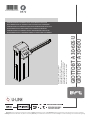 1
1
-
 2
2
-
 3
3
-
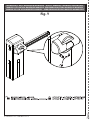 4
4
-
 5
5
-
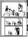 6
6
-
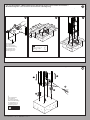 7
7
-
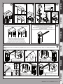 8
8
-
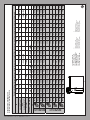 9
9
-
 10
10
-
 11
11
-
 12
12
-
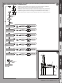 13
13
-
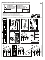 14
14
-
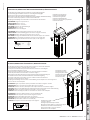 15
15
-
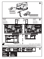 16
16
-
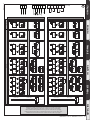 17
17
-
 18
18
-
 19
19
-
 20
20
-
 21
21
-
 22
22
-
 23
23
-
 24
24
-
 25
25