
2101309000_31-P5611OT_00_01_WEB 90 × 115 mm
www.emos.eu
P5611OT
GB Wireless Thermostat
CZ Bezdrátový termostat
SK Bezdrôtový termostat
PL Termostat bezprzewodowy
HU Vezeték nelküli termosztát
SI Brezžični termostat
RS|HR|BA|ME Bežični termostat
DE Drathloser Thermostat
UA Бездротовий термостат
RO|MD Termostat fără r
LT Belaidis termostatas
LV Bezvadu termostats
EE Juhtmevaba termostaat
BG Безжичен термостат
FR Thermostat sans l
IT Termostato senza li
ES Termostato inalámbrico
NL Draadloze thermostaat

2
1
2
111
212
313
414
515
6 16
7
17
8
18
9
19
10
20
21
1.
2. rear part
zadní část
zadná časť
tylna część
hátulsó rész
zadnji del
Stražnji dio
Rückseite
нижня частина
partea din spate
Galinė dalis
Aizmugure
tagakülg
задна част
Partie avant
Parte posteriore
Parte trasera
Achterste deel
front part
přední část
predná časť
przednia część
elülső rész
sprednji del
Prednji dio
Vorderseite
верхня частина
partea frontală
Priekinė dalis
Priekšpuse
esikülg
предна част
Partie arrière
Parte anteriore
Parte delantera
Voorstedeel

3
31 2
3
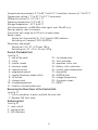
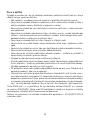
GB | Wireless Thermostat
The P5611OT thermostat is designed for controlling heating and air-conditioning
systems. Unlike conventional home thermostats, the P5611OT thermostatic system
has a separate, wirelessly connected control unit (transmitter) and a switching unit
(receiver). The switching unit is used to connect and switch heating/air-conditioning
systems while the portable control unit is used to control and adjust temperature. The
units communicate with each other via radio signal. The advantage of the system is
its variability and easier access to temperature controls.
Important
• Before rst use, make sure to read carefully the Operating Manual for the thermo-
stat, as well as the manual for the boiler or air-conditioning equipment.
• Turn o power before installing the thermostat!
• Installation should be carried out by a qualied professional!
• Abide by prescribed standards during installation.
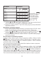
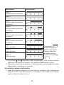
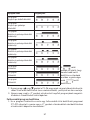
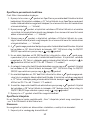
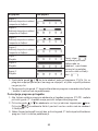
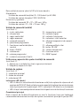
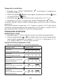
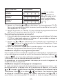
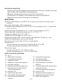
SPECIFICATIONS
Switched load: max. 230 V AC; 16 A for resistive load; 5 A for inductive load
Clock accuracy: ±60 seconds/month

4
Temperature measurement: 0 °C to 40 °C with 0.1 °C resolution; accuracy ±1 °C at 20 °C
Temperature setting: 7 °C to 30 °C in 0.2 °C increments
Dierential setting: 0.1; 0.2; 0.5; 1 °C
Operating temperature: 0 °C to 40 °C
Storage temperature: -10 °C to 60 °C
Unit interconnection: via 868 MHz radio signal, max. 25 mW e.r.p.
Pairing capacity: max. 6 receivers
Transmitter unit range: up to 100 m in an open space
Power supply:
Control unit (transmitter) 2× 1.5 V type AA (LR6) batteries
Switching unit (receiver) 230 V AC/50 Hz
Dimensions and weight:
Control unit: 23 × 97 × 122 mm; 143 g
Switching unit: 37 × 115 × 91 mm; 150 g
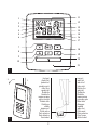
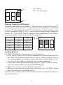
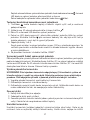
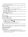
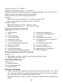
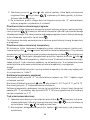
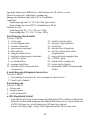
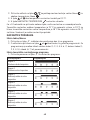
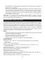
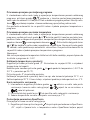
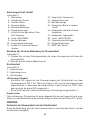
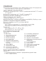
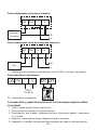
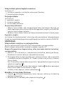
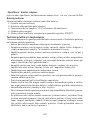
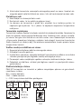
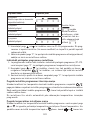
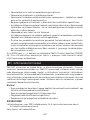
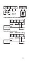
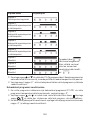
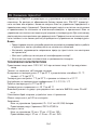
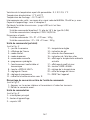
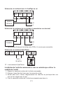
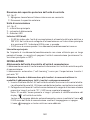
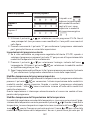
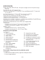
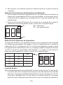
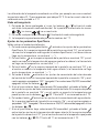
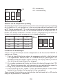
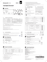
Control (Portable) Unit
(see Fig. 1)
1 – day of the week
2 – clock
3 – comfort mode
4 – economy mode
5 – manual control
6 – programme preset
7 – comfort/economy mode switch
8 – UP button
9 – change clock
10 – change programme
11 – wireless communication icon
12 – set temperature
13 – frost indication
14 – operation status icon
15 – battery status indication
16 – current room temperature
17 – day prole
18 – DOWN button
19 – change temperature
20 – illuminate screen
21 – RESET
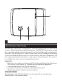
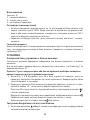
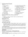
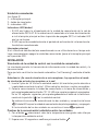
Removing the Rear Cover of the Control Unit
(see Fig. 2)
1. Use a screwdriver to press and hold the inner lock.
2. Remove THE front cover.
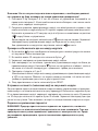
Switching Unit
(see Fig. 3)
1 – main switch
2 – pairing button
3 – LED indicators

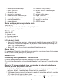
5
LED Indicators
• Blue LED indicates the switching unit is powered by 230 V AC. If the unit is not con-
nected to power or if the main switch is in the OFF position, the blue LED is not lit.
• Red LED is lit while the heating/air-conditioning system is active.
Main Switch
If the heating/air-conditioning system is not used for an extended period of time, it is
recommended to turn the switching unit o (move the main switch to the OFF position).
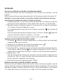
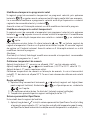
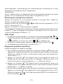
INSTALLATION
Pairing the Control Unit with the Switching Unit
Pairing enables transmission of information between the control unit and the switch-
ing unit.
The units pair automatically (self-learning) after pressing the “ID” button.
Attention: When pairing two or more receivers, it is necessary to have pairing
mode activated on all receivers simultaneously!
1. Insert 2× 1.5 V AA batteries into the control unit (make sure polarity of the batteries
is correct). Use alkaline batteries only, not rechargeable ones.
2. Connect the switching unit correctly to the power source, and press and hold the
“ID” button; the top red LED starts ashing.
Long-press the screen illumination button ( ) on the control unit within 10
seconds.
Both units will automatically pair and the icon will be displayed. The red LED
on the switching unit will stop ashing and goes out.
If the pairing of the units fails, the icon will be ashing instead.
Testing Wireless Communication between the Units
1. Use the button to select a temperature a few degrees higher than the current
room temperature.
2. Wait for approximately 10 seconds or press the button.
3. The red LED on the switching unit will light up.
4. If the LED does not light up, move the control unit closer to the switching unit.
Press the button to set a value which is lower than the room temperature – the
receiver must switch o.
5. Repeat steps 1 to 4.
The maximum range between the control and switching unit is 100 m in an open
space. The range may decrease indoors as the signal has to pass through walls
and other obstacles.
6. Press the “RESET” button once the test is complete.

6
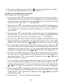
Deleting the Memory (Code) of Paired Units
To delete the pairing code used between the control and switching unit, follow the
instructions below. Press and hold the “ID” button on the switching unit; the red LED
will start ashing. Short press the “ID” button again within 10 seconds. The red LED
will stop ashing and goes out. The pairing code is deleted.
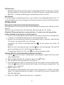
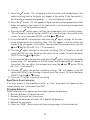
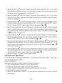
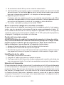
Replacing the Original Thermostat
ATTENTION: Before replacing the thermostat, disconnect the heating/air-condi-
tioning system from the power in your at. This will prevent potential injury by
electric current. Before disconnecting the leads, read the following instructions
carefully.
1. Turn o the original thermostat and remove the thermostat cover.
2. Unscrew the thermostat from the wall panel.
3. Unscrew the connecting rear panel of the thermostat from the wall. Pull the
rear panel out a sort distance from the wall, but do not disconnect any wires yet.
Marking Wires
1. Identify and disconnect each wire.
2. Secure the wires against getting torn out.
3. If the hole behind the thermostat is too large, seal it with insulating foam to prevent
air ow. This is to prevent incorrect temperature measurement.
Thermostat Placement
Thermostat (control unit) location signicantly aects its function. Place it in a room
where members of the family spend most of their time. Choose a spot preferably on
an inside wall where air circulates freely and there is no direct sunlight. Do not place
the thermostat in the vicinity of heat sources (such as TV sets, radiators, fridges), or
close to a door (due to frequent shocks or vibrations). Failure to comply with these
recommendations will prevent proper control over room temperature.
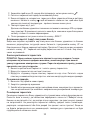
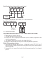
Mounting the Switching Unit onto the Wall
1. Remove the rear cover of the switching unit.
2. Mark positions for holes.
3. Drill two holes, carefully insert the plastic wall plugs into them and use two screws
to mount the rear cover of the switching unit.
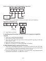
4. Connect the wires to the labelled terminals according to the wiring diagram.
5. Complete the installation by tting the switching unit onto the mounted rear cover.

7
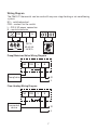
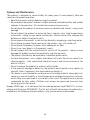
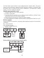
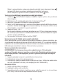
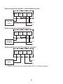
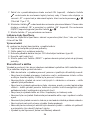
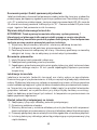
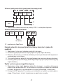
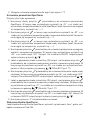
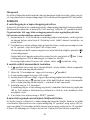
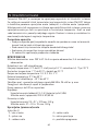
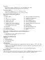
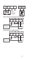
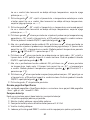
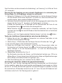
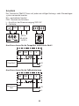
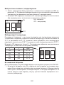
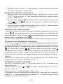
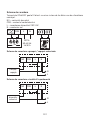
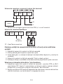
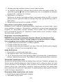
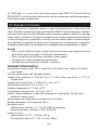
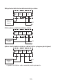
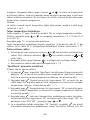
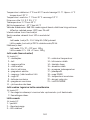
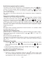
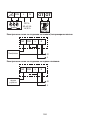
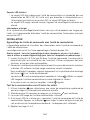
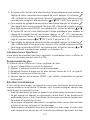
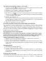
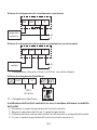
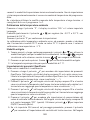
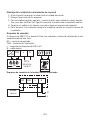
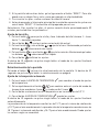
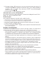
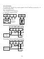
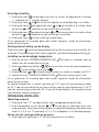
Wiring Diagram
The P5611OT thermostat can be used with any one-stage heating or air-conditioning
system.
NO – switched contact
COM – contact for the switch
L – 230 V AC power connection
N – neutral conductor
N/O
ON COM
230 V~
50–60 Hz
16 (5) A
L N
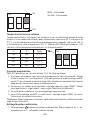
Pump/Motorised Valve Wiring Diagram
COM
Pump/valve
NO L
N
L
N
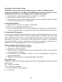
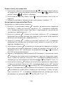
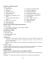
Floor Heating Wiring Diagram
COM
connected
device
NO L
N
L
N

8
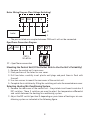
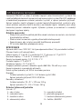
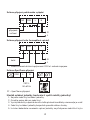
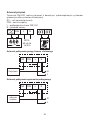
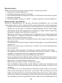
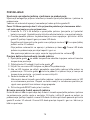
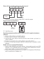
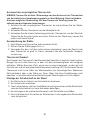
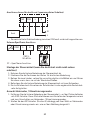
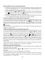
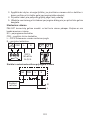
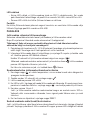
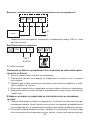
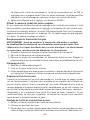
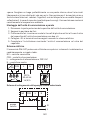
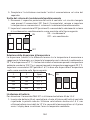
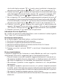
Boiler Wiring Diagram (Zero Voltage Switching)
COM
boiler
NO L
N
L
N
• The pre-installed wire coupler between COM and L will not be connected.
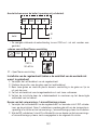
OpenTherm Connection Diagram
N/O
ON COM
230 V~
50–60 Hz
L N
OT – OpenTherm connection
Mounting the Control Unit (If You Do Not Wish to Use the Unit’s Portability)
1. Remove the control unit’s rear cover.
2. Mark positions of the holes for rear cover.
3. Drill two holes, carefully insert plastic wall plugs and push them in ush with
the wall.
4. Use two screws to mount the rear cover of the control unit.
5. Complete the installation by tting the switching unit onto the mounted rear cover.
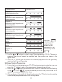
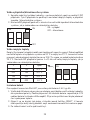
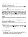
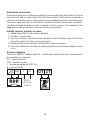
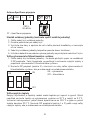
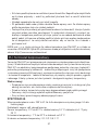
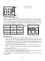
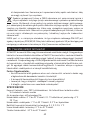
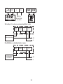
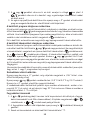
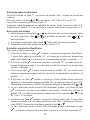
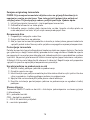
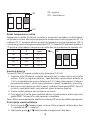
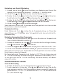
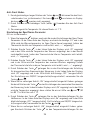
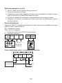
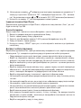
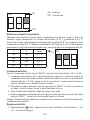
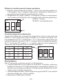
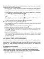
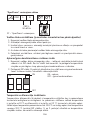
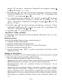
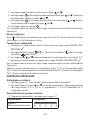
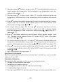
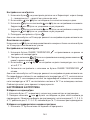
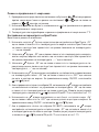
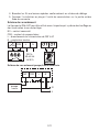
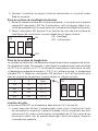
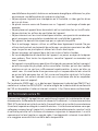
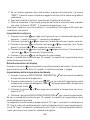
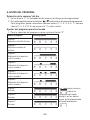
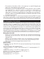
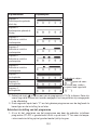
Selecting Heating/Air-Conditioning System
1. Remove the rear cover of the control unit – the printed circuit board inside has 3
DIP switches. These 3 switches are used to adjust the temperature dierential
and switch between the heating/air-conditioning system.
2. Adjust the DIP switch (position 3) depending on your choice of heating or air-con-
ditioning system as indicated in the following gure.

9
ON
123
ON
OFF
ON – heating
OFF – air-conditioning
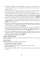
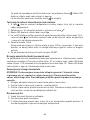
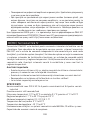
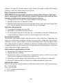
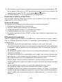
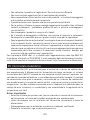
Selecting Temperature Dierential
The temperature dierential (hysteresis) is the dierence in temperature required for
switching the system on and o. If, for example, you set the temperature in the heating
system to 20 °C and dierential to 0.2 °C, the thermostat activates heating as soon
as room temperature drops to 19.8 °C and switches heating o when temperature
reaches 20.2 °C. Set the DIP switches (positions 1 and 2) depending on your choice of
temperature dierential as indicated in the following gure.
1 2 Span
ON ON 0,1 °C
OFF ON 0,2 °C
ON OFF 0,5 °C
OFF OFF 1,0 °C
ON
123
Installing Batteries
The P5611OT thermostat is powered by two 1.5 V AA batteries.
1. Insert two AA batteries into the battery compartment located inside the control
unit. Make sure to observe correct polarity. Use 1.5 V alkaline batteries only; do
not use rechargeable 1.2 V batteries (due to their lower voltage). When you rst
start the unit, the screen must show the time and room temperature.
2. If the screen shows dierent data, gently press the “RESET” button. To do this,
use a thin, straight object, such as an unfolded paper clip.
3. Replace the rear cover once the batteries are in place.
4. Before you turn on the main switch of the switching unit, press the “RESET” button
once. The thermostat is now ready for use.
Attention: After inserting batteries, the transmitter needs up to about 30 minutes to
stabilise parameters!

10
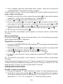
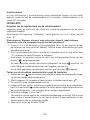
Setting the Time/Date
1. Press the button to set the day and time. The day indicator (number 1 – Monday
to 7 – Sunday) will start ashing.
2. Use the or button to select the corresponding day number.
3. Press the button and use the or button to set hours. Hold the or
button to speed up the adjustment.
4. Press the button and use the or button to set minutes. Hold the or
button to speed up the adjustment.
5. Conrm the setting using the button.
If no button is pressed for 10 seconds, setting mode ends automatically.
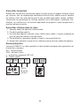
Screen Illumination
Pressing the button activates screen illumination. If no button is pressed for 10
seconds, illumination will turn o.
Setting Temperature
1. Press the CHANGE TEMPERATURE button to switch to temperature setting
mode.
2. Repeatedly press the button to switch between economy mode ( icon)
and comfort mode ( icon).
3. Use the or button to set both temperatures in 0.2 °C increments.
4. Save the setting by pressing the CHANGE TEMPERATURE button again.
If no button is pressed for 10 seconds, setting mode ends automatically.
The default comfort temperature is 21 °C for the heating system and 23 °C for air-con-
ditioning; the default economy temperature is 18 °C for the heating system and 26 °C
for air-conditioning. Values can be changed, as necessary.
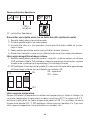
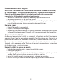
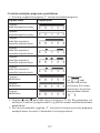
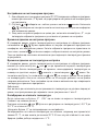
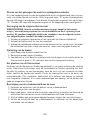
SETTING A PROGRAMME
Selecting Week/Day
1. Press the “P” button; the day indicator will indicate which day is being programmed.
2. Repeatedly press the or button to select the day you wish to programme.
You can choose to programme: the whole week (1, 2, 3, 4, 5, 6, 7), workdays (1,
2, 3, 4, 5), weekend (6, 7) or each day individually.
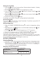
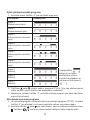
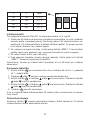
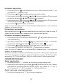
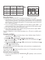
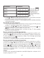
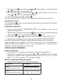
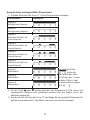
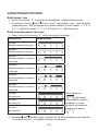
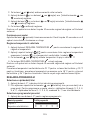
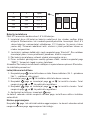
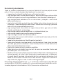
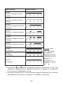
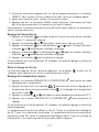
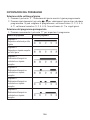
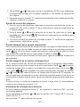
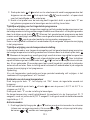
Selecting a Pre-Set Programme
1. Press the “P” button again to set a programme.
Programme Number Programme Prole
Programme 1:
Comfort temperature all day

11
Programme Number Programme Prole
Programme 2:
Economy temperature all day
Programme 3:
Combination of comfort temperature and
economy temperature
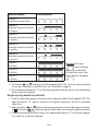
Programme 4:
Combination of comfort temperature and
economy temperature
Programme 5:
Combination of comfort temperature and
economy temperature
Programme 6:
Combination of comfort temperature and
economy temperature
Programme 7:
Custom Dark bars
indicate comfort
mode settings,
otherwise the
thermostat is set
to economy mode
.
Programme 8:
Custom
Programme 9:
Custom
2. Use the or button to select one of the programmes, P1–P6. These pro-
grammes are pre-set (cannot be modied) and their proles are shown in the
gure above.
3. Press the “P” button again to conrm the selected programme for the given day/
week and exit the setting mode.
Setting a Custom Programme
1. If you select a custom programme (P7–P9) during programme selection, you can
press the “P” button to adjust the programme’s temperature settings.
2. Press the or button to choose an hour, which is indicated with the ashing
of the icon. Press to choose whether you want the system to be set to
comfort or economy mode at that time.
3. After you have set the prole for the entire day, press the “P” button to acknowledge
the selected programme and exit the setting mode.

12
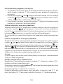
Temporary Change of a Set Programme
In standard mode, where temperature is controlled by a selected programme, pressing
the button switches from the currently set programme to comfort or economy
mode. When the selected programme is switched over in this way, the icon is
displayed together with the selected control mode icon.
This setting will cancel automatically upon the next temperature change in the
programme.
Temporary Change of Temperature Setting
In standard mode, where temperature is controlled by a selected programme, you
can press the or button to override the current temperature setting. When the
temperature is changed, the newly set temperature will be displayed together with
the icon, with the and icons disabled. Press any button (except or ) to
exit the temperature setting mode. If no button is pressed for 10 seconds, setting mode
ends automatically. This setting will cancel automatically upon the next temperature
change in the programme.
Note: If you wish to use the manually changed temperature for an extended period of
time, we recommend doing so in programme no. 1 or 2.
Calibrating Room Temperature
Long-press the “P” button. “CAL” will appear on the screen and the set temperature
value will be ashing.
Repeatedly press the or button to adjust the temperature (-3.0 °C to 3.0 °C, in
0.5 °C increments).
Press the “P” button to conrm the setting.
Calibration of room temperature is used, for example, if the thermostat shows 21 °C
but you want it to show 20 °C. In that case, the calibration value should be set to -1 °C.
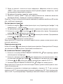
Anti-Freeze Mode
1. Simultaneously long-pressing the and button activates anti-freeze mode
(for heating mode only). and will appear on the screen and and
will not be displayed.
2. Press any button (except ) to end anti-freeze mode.
3. Default temperature for anti-freeze mode is 7 °C.
Setting OpenTherm Parameters
Applies only to heating mode.
1. Long-press the button to access OpenTherm settings. “01” will appear in
the left corner and water temperature in the OpenTherm boiler will appear in
the centre (if the thermostat is not receiving a temperature reading, “---” will
be displayed instead).

13
2. Press the button. “02” will appear in the left corner and temperature of the
water returning back to the boiler will appear in the centre (if the thermostat is
not receiving a temperature reading, “---” will be displayed instead).
3. Press the button. “03” will appear in the left corner and the temperature of hot
water will appear in the centre (if the thermostat is not receiving a temperature
reading, “---” will be displayed instead).
4. Pressing the button opens settings for temperature limit switching values.
“04” will appear in the left corner and OFF will start ashing in the centre of the
screen. To switch between ON/OFF, use the or button.
5. If you selected ON in the previous step, pressing opens settings for the max-
imum temperature limit switching value. “05” will appear in the left corner and
temperature will appear in the centre. You can adjust the temperature using the
and button (30 to 80 °C in 1 °C increments).
6. Pressing opens settings for hot water switching. “06” will appear in the left
corner and OFF will start ashing in the centre of the screen. To switch between
ON/OFF, use the or button.
7. If you selected ON in the previous step, pressing opens settings for hot water
temperature. “07” will appear in the left corner and temperature will appear in
the centre. You can adjust the temperature using the and button (25 to
65 °C in 1 °C increments).
8. Pressing opens the control switching settings. “08” will appear in the left
corner and ON will start ashing in the centre of the screen. To switch between
ON/OFF, use the or button.
9. Press the “P” button to conrm the setting.
OpenTherm Error Indication
If an error occurs in the OpenTherm boiler, an “Exxx” error code will appear on the
screen, where “xxx” is between 0 and 255.
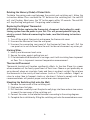
Changing Batteries
When the battery icon appears on the screen, replace the batteries:
1. Switch o power to the receiver unit.
2. Remove the control unit’s rear cover.
3. Replace the batteries with new 1.5 V alkaline AA batteries.
4. Replace the rear cover.
5. Press the “RESET” button once and then restore power to the receiver unit.

14
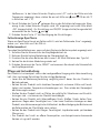
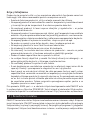
Upkeep and Maintenance
The product is designed to serve reliably for many years if used properly. Here are
some tips for proper operation:
• Read the manual carefully before using this product.
• Do not expose the product to direct sunlight, extreme cold and humidity, and sudden
changes in temperature. This would reduce measuring accuracy.
• Do not place the product in locations prone to vibration and shocks – may cause
damage.
• Do not subject the product to excessive force, impacts, dust, high temperatures
or humidity – doing so may cause malfunction, shorten battery life, damage the
batteries or deform the plastic parts.
• Do not expose the product to rain or high humidity, dropping or splashing water.
• Do not place any open ame sources on the product, e.g. a lit candle, etc.
• Do not place the product in places with inadequate air ow.
• Do not insert any objects in the product’s vents.
• Do not tamper with the internal electric circuits of the product – doing so may
damage the product and will automatically void the warranty.
• The product should only be repaired by a qualied professional.
• To clean the product, use a slightly moistened soft cloth. Do not use solvents or
cleaning agents – they could erode the plastic parts and cause corrosion of the
electric circuits.
• Do not immerse the product in water or other liquids.
• In the event of damage or defect on the product, do not perform any repairs by
yourself. Have it repaired in the shop where you bought it.
• This device is not intended for use by persons (including children) whose physical,
sensory or mental disability or lack of experience and expertise prevents safe use,
unless they are supervised or instructed in the use of the appliance by a person
responsible for their safety. Children must always be supervised to ensure they
do not play with the device.
Hereby, EMOS spol. s r. o. declares that the radio equipment type P5611OT is in com-
pliance with Directive 2014/53/EU. The full text of the EU declaration of conformity is
available at the following internet address: http://www.emos.eu/download.

15
CZ | Bezdrátový termostat
Termostat P5611OT je určen k ovládání topných nebo klimatizačních systémů. Na
rozdíl od běžných domácích termostatů má termostatický systém P5611OT oddělenou
a bezdrátově propojenou ovládací jednotku (vysílač) a spínací jednotku (přijímač).
Spínací jednotka slouží k připojení a spínání topných/klimatizačních systémů a pře-
nosná ovládací jednotka slouží k obsluze a nastavování teplot. Jednotky mezi sebou
komunikují pomocí rádiového signálu. Výhodou systému je variabilnost a snadnější
dostupnost regulace teploty.
Důležitá upozornění
• Před prvním použitím pečlivě přečtěte návod k obsluze termostatu, ale i kotle či
klimatizačního zařízení.
• Před instalací termostatu vypněte přívod elektrického proudu!
• Doporučujeme, aby instalaci prováděl kvalikovaný pracovník!
• Při instalaci dodržujte předepsané normy.
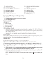
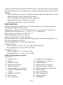
SPECIFIKACE
Spínaná zátěž: max. 230 V AC; 16 A pro odporové zatížení; 5 A pro indukční zatížení
Přesnost hodin: ±60 sekund/měsíc
Měření teploty: 0 °C až 40 °C s rozlišením 0,1 °C; přesnost ±1 °C při 20 °C
Nastavení teploty: 7 °C až 30 °C v krocích po 0,2 °C
Rozptyl nastavené teploty: 0,1; 0,2; 0,5; 1 °C
Provozní teplota: 0 °C až 40 °C
Skladovací teplota: -10 °C až 60 °C
Propojení jednotek: pomocí rádiového signálu 868 MHz, 25 mW e.r.p. max.
Kapacita párování: maximálně 6 přijímačů
Dosah vysílací jednotky: až 100 m ve volném prostoru
Napájení:
Ovládací jednotka (vysílač) 2× 1,5 V baterie typ AA (LR6)
Spínací jednotka (přijímač) 230 V AC/50 Hz
Rozměry a hmotnost:
Ovládací jednotka: 23 × 97 × 122 mm; 143 g
Spínací jednotka: 37 × 115 × 91 mm; 150 g
Ovládací (přenosná) jednotka
(viz obr. 1)
1 – den v týdnu
2 – zobrazení hodin
3 – komfortní režim
4 – ekonomický režim
5 – manuální ovládání
6 – předvolba programů
7 – komfortní/ekonomický provoz
8 – tlačítko „NAHORU“

16
9 – nastavení času
10 – nastavení programu
11 – ikona bezdrátové komunikace
12 – nastavená teplota
13 – indikace námrazy
14 – ikona provozu
15 – indikace stavu baterií
16 – zobrazení aktuální pokojové
teploty
17 – zobrazení prolu dne
18 – tlačítko „DOLŮ“
19 – nastavení teploty
20 – podsvícení displeje
21 – RESET přístroje
Sejmutí zadního krytu ovládací jednotky
(viz obr. 2)
1. Šroubovákem zatlačte a držte vnitřní zámek.
2. Odstraňte přední kryt.
Spínací jednotka
(viz obr. 3)
1 – hlavní spínač
2 – párovací tlačítko
3 – LED indikátory
LED indikátory (diody)
• Modrá LED signalizuje napájení spínací jednotky z napájecí sítě 230 V AC. Není-li
jednotka připojena k napájení nebo je-li hlavní spínač v pozici vypnuto (OFF), modrý
LED indikátor nesvítí.
• Červená LED svítí po dobu sepnutí topného/klimatizačního zařízení.
Hlavní spínač
Pokud není vytápěcí/klimatizační systém delší dobu používán, doporučujeme spínací
jednotku vypnout (hlavní spínač přepnout do polohy OFF).
INSTALACE
Spárování ovládací jednotky se spínací jednotkou
Spárování umožňuje přenos informací mezi ovládací a spínací jednotkou.
K nastavení se používá automatické spárování („self-learning“) pomocí tlačítka „ID“.
Upozornění: Při párování dvou a více přijímačů je nutné aktivovat párovací režim u
všech přijímačů zároveň!
1. Vložte baterie 2× 1,5 V AA do ovládací jednotky (při vkládání dejte pozor na správnou
polaritu baterií). Používejte pouze alkalické baterie, ne nabíjecí.
2. Připojte správně spínací jednotku ke zdroji napětí a stiskněte dlouze tlačítko „ID“,
začne blikat horní červená dioda.
Do 10 sekund stiskněte dlouze tlačítko podsvícení displeje ( ) na ovládací jed-
notce.

17
Dojde k automatickému spárování obou jednotek, bude zobrazena ikona . Červená
LED dioda na spínací jednotce přestane blikat a zhasne.
Pokud nedojde ke spárování obou jednotek, bude ikona blikat.
Testování bezdrátové komunikace mezi jednotkami
1. Tlačítkem zvolte hodnotu teploty o několik stupňů vyšší, než je současná
pokojová teplota.
2. Vyčkejte cca 10 sekund nebo potvrďte stiskem tlačítka .
3. Rozsvítí se červená LED dioda na spínací jednotce.
4. Pokud se LED dioda nerozsvítí, přemístěte ovládací jednotku blíže ke spínací
jednotce. Stiskněte tlačítko pro nastavení hodnoty tak, aby byla nižší, než je
teplota pokojová – musí dojít k vypnutí přijímače.
5. Zopakujte kroky 1 až 4.
Dosah mezi ovládací a spínací jednotkou je max. 100 m v otevřeném prostoru. Ve
vnitřních prostorách se může dosah zmenšit z důvodu blokování signálu stěnami
a jinými překážkami.
6. Po provedení testování stiskněte tlačítko „RESET“.
Vymazání paměti (kódu) spárovaných jednotek
Pokud potřebujete vymazat párovací kód mezi ovládací a spínací jednotkou, postupujte
podle následujících pokynů. Stiskněte dlouze tlačítko „ID“ na spínací jednotce, rozbliká
se červená LED dioda. Do 10 sekund stiskněte znovu krátce tlačítko „ID“. Červená LED
dioda přestane blikat a zhasne. Párovací kód je vymazán.
Výměna původního termostatu
UPOZORNĚNÍ: Před výměnou termostatu odpojte topný / klimatizační systém od
hlavního zdroje el. napětí ve vašem bytě. Zabráníte možnému úrazu elektrickým
proudem. Před odpojením přívodů si pozorně přečtěte následující instrukce.
1. Vypněte původní termostat a odstraňte kryt termostatu.
2. Odšroubujte termostat z nástěnné desky.
3. Odšroubujte spojující zadní desku termostatu od zdi. Odtáhněte zadní desku na
malou vzdálenost od zdi, ale neodpojujte zatím žádné dráty.
Značení drátů
1. Každý drát identikujte a odpojte.
2. Zabezpečte dráty proti vytržení.
3. Zamezte průniku vzduchu izolační pěnou, pokud je prostor za termostatem příliš
velký. Zabráníte tak nesprávnému měření teploty.
Umístění termostatu
Umístění termostatu (ovládací jednotky) výrazně ovlivňuje jeho funkci. Dejte jej do
místnosti, kde se nejčastěji zdržují členové rodiny. Zvolte místo, nejlépe na vnitřní

18
zdi, kde vzduch volně cirkuluje a kam nedopadá přímé sluneční záření. Termostat
neumisťujte ani do blízkosti tepelných zdrojů (televizorů, radiátorů, chladniček) nebo
do blízkosti dveří (z důvodu častých otřesů). Nedodržíte-li tato doporučení, nebude
teplota v místnosti udržována správně.
Montáž spínací jednotky na zeď
1. Sejměte zadní část krytu spínací jednotky.
2. Označte si pozice děr.
3. Vyvrtejte dvě díry, opatrně do nich vložte plastové hmoždinky a dvěma šrouby
přichytněte zadní část krytu spínací jednotky.
4. Připojte dráty do označených svorek dle schéma zapojení.
5. Instalaci dokončete nasazením spínací jednotky na přichycenou zadní část krytu.
Schéma zapojení
Termostat P5611OT lze používat s jakýmkoliv jednostupňovým topným či klimatizačním
systémem.
NO – spínaný kontakt
COM – kontakt spínače
L – připojení napájení 230 V AC
N – nulovací vodič
N/O
ON COM
230 V~
50–60 Hz
16 (5) A
L N
Schéma připojení čerpadla/motorizovaneho ventilu
COM
čerpadlo
ventil
NO L
N
L
N

19
Schéma připojení podlahového vytápění
COM
připojené
zařízení
NO L
N
L
N
Schéma připojení kotle (beznapěťové spínání)
COM
kotel
NO L
N
L
N
• Předinstalovaná drátová spojka mezi COM a L nebude zapojena.
Schéma OpenTherm připojení
N/O
ON COM
230 V~
50–60 Hz
L N
OT – OpenTherm připojení
Montáž ovládací jednotky (nechcete-li využít mobility jednotky)
1. Sejměte zadní kryt ovládací jednotky.
2. Označte pozice děr pro zadní kryt.
3. Vyvrtejte dvě díry a opatrně do nich vložte plastové hmoždinky a zarovnejte je se zdí.
4. Zadní kryt ovládací jednotky bezpečně upevněte dvěma šrouby.
5. Instalaci dokončete nasazením spínací jednotky na přichycenou zadní část krytu.

20
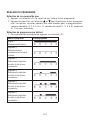
Volba vytápěcího/klimatizačního systému
1. Sejměte zadní kryt ovládací jednotky – na desce plošných spojů se nachází 3 DIP
přepínače. Tyto 3 přepínače se používají k nastavení rozptylu teploty a přepínání
topného / klimatizačního systému.
2. Nastavte DIP přepínač (pozice 3) v závislosti na vaší volbě topného či klimatizačního
systému, jak je znázorněno na následujícím obrázku.
ON
123
ON
OFF
ON – vytápění
OFF – klimatizace
Volba rozptylu teploty
Rozptyl (hystereze) je teplotní rozdíl mezi teplotou při zapnutí a vypnutí. Pokud například
nastavíte teplotu ve vytápěcím systému na 20 °C a rozptyl na 0,2 °C, termostat začne
pracovat, pokud pokojová teplota klesne na 19,8 °C a vypne se, pokud teplota dosáhne
20,2 °C. Nastavte DIP přepínače (pozice 1 a 2) dle své volby rozptylu teploty, jak je
znázorněno na následujícím obrázku.
1 2 Span
ON ON 0,1 °C
OFF ON 0,2 °C
ON OFF 0,5 °C
OFF OFF 1,0 °C
ON
123
Instalace baterií
Pro napájení termostatu P5611OT jsou určeny dvě baterie 1,5 V, typ AA.
1. Vložte dvě AA baterie do prostoru pro baterie umístěného uvnitř ovládací jednotky
dle vyznačené polarity. Používejte pouze 1,5V alkalické baterie, nepoužívejte 1,2V
nabíjecí baterie (z důvodu nižšího napětí). Při prvním spuštění musí displej ukazovat
čas a pokojovou teplotu.
2. Objeví-li se na displeji jiné údaje, stiskněte jemně tlačítko „RESET“. K tomuto
účelu použijte tenký rovný předmět, např. narovnaná kancelářská svorka na papír.
3. Po vložení baterií vraťte zpět zadní kryt.
La pagina sta caricando ...
La pagina sta caricando ...
La pagina sta caricando ...
La pagina sta caricando ...
La pagina sta caricando ...
La pagina sta caricando ...
La pagina sta caricando ...
La pagina sta caricando ...
La pagina sta caricando ...
La pagina sta caricando ...
La pagina sta caricando ...
La pagina sta caricando ...
La pagina sta caricando ...
La pagina sta caricando ...
La pagina sta caricando ...
La pagina sta caricando ...
La pagina sta caricando ...
La pagina sta caricando ...
La pagina sta caricando ...
La pagina sta caricando ...
La pagina sta caricando ...
La pagina sta caricando ...
La pagina sta caricando ...
La pagina sta caricando ...
La pagina sta caricando ...
La pagina sta caricando ...
La pagina sta caricando ...
La pagina sta caricando ...
La pagina sta caricando ...
La pagina sta caricando ...
La pagina sta caricando ...
La pagina sta caricando ...
La pagina sta caricando ...
La pagina sta caricando ...
La pagina sta caricando ...
La pagina sta caricando ...
La pagina sta caricando ...
La pagina sta caricando ...
La pagina sta caricando ...
La pagina sta caricando ...
La pagina sta caricando ...
La pagina sta caricando ...
La pagina sta caricando ...
La pagina sta caricando ...
La pagina sta caricando ...
La pagina sta caricando ...
La pagina sta caricando ...
La pagina sta caricando ...
La pagina sta caricando ...
La pagina sta caricando ...
La pagina sta caricando ...
La pagina sta caricando ...
La pagina sta caricando ...
La pagina sta caricando ...
La pagina sta caricando ...
La pagina sta caricando ...
La pagina sta caricando ...
La pagina sta caricando ...
La pagina sta caricando ...
La pagina sta caricando ...
La pagina sta caricando ...
La pagina sta caricando ...
La pagina sta caricando ...
La pagina sta caricando ...
La pagina sta caricando ...
La pagina sta caricando ...
La pagina sta caricando ...
La pagina sta caricando ...
La pagina sta caricando ...
La pagina sta caricando ...
La pagina sta caricando ...
La pagina sta caricando ...
La pagina sta caricando ...
La pagina sta caricando ...
La pagina sta caricando ...
La pagina sta caricando ...
La pagina sta caricando ...
La pagina sta caricando ...
La pagina sta caricando ...
La pagina sta caricando ...
La pagina sta caricando ...
La pagina sta caricando ...
La pagina sta caricando ...
La pagina sta caricando ...
La pagina sta caricando ...
La pagina sta caricando ...
La pagina sta caricando ...
La pagina sta caricando ...
La pagina sta caricando ...
La pagina sta caricando ...
La pagina sta caricando ...
La pagina sta caricando ...
La pagina sta caricando ...
La pagina sta caricando ...
La pagina sta caricando ...
La pagina sta caricando ...
La pagina sta caricando ...
La pagina sta caricando ...
La pagina sta caricando ...
La pagina sta caricando ...
La pagina sta caricando ...
La pagina sta caricando ...
La pagina sta caricando ...
La pagina sta caricando ...
La pagina sta caricando ...
La pagina sta caricando ...
La pagina sta caricando ...
La pagina sta caricando ...
La pagina sta caricando ...
La pagina sta caricando ...
La pagina sta caricando ...
La pagina sta caricando ...
La pagina sta caricando ...
La pagina sta caricando ...
La pagina sta caricando ...
La pagina sta caricando ...
La pagina sta caricando ...
La pagina sta caricando ...
La pagina sta caricando ...
La pagina sta caricando ...
La pagina sta caricando ...
La pagina sta caricando ...
La pagina sta caricando ...
La pagina sta caricando ...
La pagina sta caricando ...
La pagina sta caricando ...
La pagina sta caricando ...
La pagina sta caricando ...
La pagina sta caricando ...
La pagina sta caricando ...
La pagina sta caricando ...
La pagina sta caricando ...
La pagina sta caricando ...
La pagina sta caricando ...
La pagina sta caricando ...
La pagina sta caricando ...
La pagina sta caricando ...
La pagina sta caricando ...
La pagina sta caricando ...
La pagina sta caricando ...
La pagina sta caricando ...
La pagina sta caricando ...
La pagina sta caricando ...
La pagina sta caricando ...
La pagina sta caricando ...
La pagina sta caricando ...
La pagina sta caricando ...
La pagina sta caricando ...
La pagina sta caricando ...
La pagina sta caricando ...
La pagina sta caricando ...
La pagina sta caricando ...
La pagina sta caricando ...
La pagina sta caricando ...
La pagina sta caricando ...
La pagina sta caricando ...
La pagina sta caricando ...
La pagina sta caricando ...
La pagina sta caricando ...
La pagina sta caricando ...
La pagina sta caricando ...
La pagina sta caricando ...
La pagina sta caricando ...
La pagina sta caricando ...
La pagina sta caricando ...
La pagina sta caricando ...
La pagina sta caricando ...
La pagina sta caricando ...
La pagina sta caricando ...
La pagina sta caricando ...
La pagina sta caricando ...
La pagina sta caricando ...
La pagina sta caricando ...
La pagina sta caricando ...
La pagina sta caricando ...
La pagina sta caricando ...
La pagina sta caricando ...
La pagina sta caricando ...
La pagina sta caricando ...
La pagina sta caricando ...
La pagina sta caricando ...
La pagina sta caricando ...
La pagina sta caricando ...
La pagina sta caricando ...
La pagina sta caricando ...
La pagina sta caricando ...
La pagina sta caricando ...
La pagina sta caricando ...
La pagina sta caricando ...
La pagina sta caricando ...
La pagina sta caricando ...
La pagina sta caricando ...
La pagina sta caricando ...
La pagina sta caricando ...
La pagina sta caricando ...
La pagina sta caricando ...
-
 1
1
-
 2
2
-
 3
3
-
 4
4
-
 5
5
-
 6
6
-
 7
7
-
 8
8
-
 9
9
-
 10
10
-
 11
11
-
 12
12
-
 13
13
-
 14
14
-
 15
15
-
 16
16
-
 17
17
-
 18
18
-
 19
19
-
 20
20
-
 21
21
-
 22
22
-
 23
23
-
 24
24
-
 25
25
-
 26
26
-
 27
27
-
 28
28
-
 29
29
-
 30
30
-
 31
31
-
 32
32
-
 33
33
-
 34
34
-
 35
35
-
 36
36
-
 37
37
-
 38
38
-
 39
39
-
 40
40
-
 41
41
-
 42
42
-
 43
43
-
 44
44
-
 45
45
-
 46
46
-
 47
47
-
 48
48
-
 49
49
-
 50
50
-
 51
51
-
 52
52
-
 53
53
-
 54
54
-
 55
55
-
 56
56
-
 57
57
-
 58
58
-
 59
59
-
 60
60
-
 61
61
-
 62
62
-
 63
63
-
 64
64
-
 65
65
-
 66
66
-
 67
67
-
 68
68
-
 69
69
-
 70
70
-
 71
71
-
 72
72
-
 73
73
-
 74
74
-
 75
75
-
 76
76
-
 77
77
-
 78
78
-
 79
79
-
 80
80
-
 81
81
-
 82
82
-
 83
83
-
 84
84
-
 85
85
-
 86
86
-
 87
87
-
 88
88
-
 89
89
-
 90
90
-
 91
91
-
 92
92
-
 93
93
-
 94
94
-
 95
95
-
 96
96
-
 97
97
-
 98
98
-
 99
99
-
 100
100
-
 101
101
-
 102
102
-
 103
103
-
 104
104
-
 105
105
-
 106
106
-
 107
107
-
 108
108
-
 109
109
-
 110
110
-
 111
111
-
 112
112
-
 113
113
-
 114
114
-
 115
115
-
 116
116
-
 117
117
-
 118
118
-
 119
119
-
 120
120
-
 121
121
-
 122
122
-
 123
123
-
 124
124
-
 125
125
-
 126
126
-
 127
127
-
 128
128
-
 129
129
-
 130
130
-
 131
131
-
 132
132
-
 133
133
-
 134
134
-
 135
135
-
 136
136
-
 137
137
-
 138
138
-
 139
139
-
 140
140
-
 141
141
-
 142
142
-
 143
143
-
 144
144
-
 145
145
-
 146
146
-
 147
147
-
 148
148
-
 149
149
-
 150
150
-
 151
151
-
 152
152
-
 153
153
-
 154
154
-
 155
155
-
 156
156
-
 157
157
-
 158
158
-
 159
159
-
 160
160
-
 161
161
-
 162
162
-
 163
163
-
 164
164
-
 165
165
-
 166
166
-
 167
167
-
 168
168
-
 169
169
-
 170
170
-
 171
171
-
 172
172
-
 173
173
-
 174
174
-
 175
175
-
 176
176
-
 177
177
-
 178
178
-
 179
179
-
 180
180
-
 181
181
-
 182
182
-
 183
183
-
 184
184
-
 185
185
-
 186
186
-
 187
187
-
 188
188
-
 189
189
-
 190
190
-
 191
191
-
 192
192
-
 193
193
-
 194
194
-
 195
195
-
 196
196
-
 197
197
-
 198
198
-
 199
199
-
 200
200
-
 201
201
-
 202
202
-
 203
203
-
 204
204
-
 205
205
-
 206
206
-
 207
207
-
 208
208
-
 209
209
-
 210
210
-
 211
211
-
 212
212
-
 213
213
-
 214
214
-
 215
215
-
 216
216


in altre lingue
- slovenčina: Emos P5611OT Návod na používanie
- română: Emos P5611OT Instrucțiuni de utilizare
Documenti correlati
Altri documenti
-
Atlantic NAVILINK H55 Manuale del proprietario
-
ACV RC35 Technical Manual
-
Johnson Controls York DPC-1 Operating And Maintenance Instructions Manual
-
 Honeywell Home T140 Digital Thermostat Guida d'installazione
-
-
Siemens RDE100.1 Programmable Room Thermostat Manuale utente
-
-
Honeywell HR40 Manuale del proprietario
-
Danfoss TP7000 Guida utente
-
PNI CT25PW Manuale utente
