AJA OG-X-FR Manuale utente
- Categoria
- Apparecchiature musicali supplementari
- Tipo
- Manuale utente

OG-X-FR
openGear Frame
Version 1.0r1
Published July 30, 2018
Installation and Operation Guide

OG-X-FR openGear Frame v1.0r1 2 www.aja.com
Notices
Trademarks
AJA® and Because it matters.® are registered trademarks of AJA Video Systems, Inc.
for use with most AJA products. AJA™ is a trademark of AJA Video Systems, Inc. for
use with recorder, router, software and camera products. Because it matters.™ is a
trademark of AJA Video Systems, Inc. for use with camera products.
CION®, Corvid Ultra®, lo®, Ki Pro®, KONA®, KUMO®, ROI® and T-Tap® are registered
trademarks of AJA Video Systems, Inc.
AJA Control Room™, KiStor™, Science of the Beautiful™, TruScale™, TruZoom™,
V2Analog™ and V2Digital™ are trademarks of AJA Video Systems, Inc.
All other trademarks are the property of their respective owners.
Copyright
Copyright © 2018 AJA Video Systems, Inc. All rights reserved. All information in
this manual is subject to change without notice. No part of the document may be
reproduced or transmitted in any form, or by any means, electronic or mechanical,
including photocopying or recording, without the express written permission of AJA
Video Systems, Inc.
Contacting AJA Support
When calling for support, have all information at hand prior to calling. To contact AJA
for sales or support, use any of the following methods:
Telephone +1.530.271.3190
FAX +1.530.271.3140
Web https://www.aja.com
Support Email suppor[email protected]
Sales Email [email protected]

OG-X-FR openGear Frame v1.0r1 3 www.aja.com
Contents
Notices . . . . . . . . . . . . . . . . . . . . . . . . . . . . . . . . . . . . . .2
Trademarks . . . . . . . . . . . . . . . . . . . . . . . . . . . . . . . . . . . . . . . . . . . 2
Copyright . . . . . . . . . . . . . . . . . . . . . . . . . . . . . . . . . . . . . . . . . . . . 2
Contacting AJA Support . . . . . . . . . . . . . . . . . . . . . . . . . . . . . . . . . . . 2
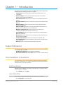
Chapter 1 – Introduction . . . . . . . . . . . . . . . . . . . . . . . . . . .5
Related Publications . . . . . . . . . . . . . . . . . . . . . . . . . . . . . . . . . . . . . 5
Documentation Conventions . . . . . . . . . . . . . . . . . . . . . . . . . . . . . . . .5
Interface Elements . . . . . . . . . . . . . . . . . . . . . . . . . . . . . . . . . . . . . 5
User Entered Text. . . . . . . . . . . . . . . . . . . . . . . . . . . . . . . . . . . . . .5
Referenced Guides . . . . . . . . . . . . . . . . . . . . . . . . . . . . . . . . . . . . . 6
Menu Sequences . . . . . . . . . . . . . . . . . . . . . . . . . . . . . . . . . . . . . . 6
Chapter 2 – Before You Begin . . . . . . . . . . . . . . . . . . . . . . . .7
Overview. . . . . . . . . . . . . . . . . . . . . . . . . . . . . . . . . . . . . . . . . . . . .7
Features . . . . . . . . . . . . . . . . . . . . . . . . . . . . . . . . . . . . . . . . . . . . . 7
Workow. . . . . . . . . . . . . . . . . . . . . . . . . . . . . . . . . . . . . . . . . . . . .8
Chapter 3 – Hardware Overview . . . . . . . . . . . . . . . . . . . . . .9
Front Panel Overview . . . . . . . . . . . . . . . . . . . . . . . . . . . . . . . . . . . . .9
OG-X-FR Interior . . . . . . . . . . . . . . . . . . . . . . . . . . . . . . . . . . . . . . . 10
Rear Panel Overview . . . . . . . . . . . . . . . . . . . . . . . . . . . . . . . . . . . . 10
openGear Rear Modules . . . . . . . . . . . . . . . . . . . . . . . . . . . . . . . . 11
Chapter 4 – Physical Installation. . . . . . . . . . . . . . . . . . . . . .13
Before You Begin. . . . . . . . . . . . . . . . . . . . . . . . . . . . . . . . . . . . . . . 13
Static Discharge. . . . . . . . . . . . . . . . . . . . . . . . . . . . . . . . . . . . . . 13
Ventilation and Cooling . . . . . . . . . . . . . . . . . . . . . . . . . . . . . . . . . . 13
Ventilation . . . . . . . . . . . . . . . . . . . . . . . . . . . . . . . . . . . . . . . . . 13
Cooling Fan Module . . . . . . . . . . . . . . . . . . . . . . . . . . . . . . . . . . . 14
Airow Requirements . . . . . . . . . . . . . . . . . . . . . . . . . . . . . . . . . . 14
Installation Requirements . . . . . . . . . . . . . . . . . . . . . . . . . . . . . . . 14
Installing the Rear Support Bars and Brackets. . . . . . . . . . . . . . . . . . . 14
Installing the FSB-OGX . . . . . . . . . . . . . . . . . . . . . . . . . . . . . . . . . 15
Connecting to a Power Supply . . . . . . . . . . . . . . . . . . . . . . . . . . . . 16
Chapter 5 – Ethernet Cabling . . . . . . . . . . . . . . . . . . . . . . . 18
Cabling the Ethernet Port on the OG-X-FR Frame . . . . . . . . . . . . . . . . . . 18
Required Pinouts . . . . . . . . . . . . . . . . . . . . . . . . . . . . . . . . . . . . . 18
Connecting to a Network. . . . . . . . . . . . . . . . . . . . . . . . . . . . . . . . 18
Chapter 6 – Reference Cabling . . . . . . . . . . . . . . . . . . . . . . 20
GFC-8322 Overview . . . . . . . . . . . . . . . . . . . . . . . . . . . . . . . . . . . . . 20
Connecting a Video Reference Source . . . . . . . . . . . . . . . . . . . . . . . . . 20
Connecting to a Reference Source . . . . . . . . . . . . . . . . . . . . . . . . . . 20
Looping the Reference Signals . . . . . . . . . . . . . . . . . . . . . . . . . . . . . . 21
Troubleshooting . . . . . . . . . . . . . . . . . . . . . . . . . . . . . . . . . . . . . 21
Chapter 7 – MFC-8322-S Network Card . . . . . . . . . . . . . . . . . 22
Overview. . . . . . . . . . . . . . . . . . . . . . . . . . . . . . . . . . . . . . . . . . . . 22
MFC-8322-S Network Card Features . . . . . . . . . . . . . . . . . . . . . . . . . 22
User Interfaces. . . . . . . . . . . . . . . . . . . . . . . . . . . . . . . . . . . . . . . 22
Installation. . . . . . . . . . . . . . . . . . . . . . . . . . . . . . . . . . . . . . . . . . . 23
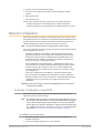
Before You Begin . . . . . . . . . . . . . . . . . . . . . . . . . . . . . . . . . . . . . 23
Installing a Network Controller Card. . . . . . . . . . . . . . . . . . . . . . . . . 23
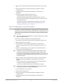
Network Conguration. . . . . . . . . . . . . . . . . . . . . . . . . . . . . . . . . . . 24
Automatic Conguration using DHCP. . . . . . . . . . . . . . . . . . . . . . . . 24
Preset Conguration using DIP Switches . . . . . . . . . . . . . . . . . . . . . . 25
Custom User Conguration via DashBoard . . . . . . . . . . . . . . . . . . . . 26

OG-X-FR openGear Frame v1.0r1 4 www.aja.com
User Rights Management. . . . . . . . . . . . . . . . . . . . . . . . . . . . . . . . 26
Using a Master Password. . . . . . . . . . . . . . . . . . . . . . . . . . . . . . . . . . 26
Before You Begin . . . . . . . . . . . . . . . . . . . . . . . . . . . . . . . . . . . . . 27
Conguring the Master Password . . . . . . . . . . . . . . . . . . . . . . . . . . 27
Accessing a Network Controller Card . . . . . . . . . . . . . . . . . . . . . . . . 28
Software Upgrades . . . . . . . . . . . . . . . . . . . . . . . . . . . . . . . . . . . . . 28
Troubleshooting . . . . . . . . . . . . . . . . . . . . . . . . . . . . . . . . . . . . . 29
Card-edge Controls for the MFC-8322-S . . . . . . . . . . . . . . . . . . . . . . . . 29
Conguring the DIP Switches . . . . . . . . . . . . . . . . . . . . . . . . . . . . . 30
Monitoring the MFC-8322-S . . . . . . . . . . . . . . . . . . . . . . . . . . . . . . . . 31
Troubleshooting Checklist. . . . . . . . . . . . . . . . . . . . . . . . . . . . . . . . . 33
MFC-8322-S Alarm Mute/Bootload Button . . . . . . . . . . . . . . . . . . . . . 33
Chapter 8 – Using DashBoard . . . . . . . . . . . . . . . . . . . . . . . 34
Overview. . . . . . . . . . . . . . . . . . . . . . . . . . . . . . . . . . . . . . . . . . . . 34
Launching DashBoard . . . . . . . . . . . . . . . . . . . . . . . . . . . . . . . . . . . 34
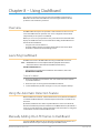
Using the Automatic Detection Feature . . . . . . . . . . . . . . . . . . . . . . . . 34
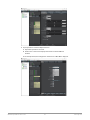
Manually Adding OG-X-FR Frames to DashBoard . . . . . . . . . . . . . . . . . . 34
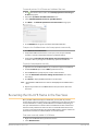
Re-naming the OG-X-FR Frame in the Tree View. . . . . . . . . . . . . . . . . . . 35
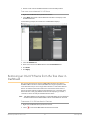
Removing an OG-X-FR Frame from the Tree View in DashBoard . . . . . . . . . 36
Auto-Discovery . . . . . . . . . . . . . . . . . . . . . . . . . . . . . . . . . . . . . . 37
Using DashBoard to Access openGear Cards in the OG-X-FR Frame . . . . . . 37
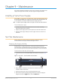
Chapter 9 – Maintenance . . . . . . . . . . . . . . . . . . . . . . . . . . 39
Installing a Frame Power Supply . . . . . . . . . . . . . . . . . . . . . . . . . . . . . 39
Fan Filter Maintenance . . . . . . . . . . . . . . . . . . . . . . . . . . . . . . . . . . . 39
Cleaning the Frame Air Filter. . . . . . . . . . . . . . . . . . . . . . . . . . . . . . 39
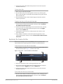
Replacing the Frame Air Filter . . . . . . . . . . . . . . . . . . . . . . . . . . . . . 40
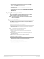
Replacing the Cooling Fan Module. . . . . . . . . . . . . . . . . . . . . . . . . . 41
Chapter 10 – Service Information . . . . . . . . . . . . . . . . . . . . . 42
Chapter 11 – Glossary . . . . . . . . . . . . . . . . . . . . . . . . . . . . 43
Appendix A – Specications . . . . . . . . . . . . . . . . . . . . . . . . 44
Appendix B – Safety and Compliance . . . . . . . . . . . . . . . . . .45
Warranty and Liability Information . . . . . . . . . . . . . . . . . . . .55
Limited Warranty on Hardware. . . . . . . . . . . . . . . . . . . . . . . . . . . . . . 55
Limitation of Liability . . . . . . . . . . . . . . . . . . . . . . . . . . . . . . . . . . . . 56
Governing Law and Language; Your Rights. . . . . . . . . . . . . . . . . . . . . . 56

OG-X-FR openGear Frame v1.0r1 5 www.aja.com
Chapter 1 – Introduction
This guide covers the installation and use of the OG-X-FR openGear High Density
Modular Frame. The following chapters are included:
• Introduction summarizes the guide and provides important terms, and
conventions.
• Before You Begin provides general information to keep in mind before
installing and conguring your OG-X-FR.
• Hardware Overview provides a basic introduction to the OG-X-FR hardware
features.
• Physical Installation provides instructions for the physical installation of the
OG-X-FR.
• Ethernet Cabling provides an overview of connecting input and output
devices to the OG-X-FR.
• Reference Cabling provides an overview of the reference distribution and
how to connect a reference source to the OG-X-FR.
• MFC-8322-S Network Card provides instructions for installing and
conguring the MFC-8322-S network controller card.
• Using DashBoard outlines the Diagnostic Panel features and displaying the
OG-X-FR in DashBoard.
• Maintenance provides instructions for cleaning the fan lter and replacing a
failed Cooling Fan Module.
• Technical Specications provides the specications for the OG-X-FR.
• Service Information provides information on the warranty and repair policy
for your OG-X-FR.
• Glossary provides a list of terms used throughout this guide.
Related Publications
It is recommended to consult the following Ross documentation before installing
and configuring your OG-X-FR:
• DashBoard User Manual, Ross Part Number: 8351DR-004
• MFC-OG3-N and MFC-8322-S User Guide, Ross Part Number: 8322DR-004-05
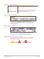
Documentation Conventions
Special text formats are used in this guide to identify parts of the user interface,
text that a user must enter, or a sequence of menus and sub-menus that must be
followed to reach a particular command.
Interface Elements
Bold text is used to identify a user interface element such as a dialog box, menu
item, or button. For example:
In the Network tab, click Apply.
User Entered Text
Courier text is used to identify text that a user must enter. For example:
In the Language box, enter English.

OG-X-FR openGear Frame v1.0r1 6 www.aja.com
Referenced Guides
Text set in bold and italic represent the titles of referenced guides, manuals, or
documents. For example:
For more information, refer to the DashBoard User Manual.
Menu Sequences
Menu arrows are used in procedures to identify a sequence of menu items that
you must follow. For example, if a step reads “File > Save As,” you would click the
File menu and then click Save As.

OG-X-FR openGear Frame v1.0r1 7 www.aja.com
Chapter 2 – Before You Begin
If you have questions pertaining to the operation of OG-X-FR, please contact us
at the numbers listed in the section "Contacting AJA Support" on page 2. Our
technical staff is always available for consultation, training, or service.
Overview
The OG-X-FR frame offers the flexibility of independent rear modules for
connectivity to a wide array of interfaces such as BNC, twisted-pair audio, and
fiber. Each frame offers a full rear module that accommodates one card each, or a
high density split rear module that accommodates two cards each. Using the split
rear module allows for up to 20 independent openGear solutions to be installed.
NOTE: Cards and rear modules designed for the DFR-8321 frames are also supported by
the OG-X-FR frames. However, some cards and rear modules may be designed
specifically for the OG-X-FR frames only. Refer to the documentation for your
openGear card for details on the frames you can use.
Features
The OG-X-FR frame includes the following features:
• Two independent looping reference inputs feed all card slots
• Can house any mix of analog, digital, video and audio cards in the same frame
• Available with individual card specic modules for connector exibility
• Optional redundant power supply is hot-swappable for 24/7 operation
• Power switch is accessible from front of the rack frame
• Power supplies are replaceable from the front of the frame without requiring
rear-frame access
• Separate power cords to each supply for power feed redundancy
• PowerLock cord retainer mechanism guards against accidental power loss
• Durable powder-coat paint nish
• Removable hinged front door for easy card insertion and removal, and
exibility in servicing the cooling fans
• Aluminum and steel construction to reduce weight and increase strength
• 2RU frame houses up to 20 cards
• Robust 500W power supply with two integral cooling fans per power supply
• Comes standard with the Cooling Fan Module for increased ventilation and
enhanced reliability
• Supports Gigabit ethernet connectivity to each openGear card in the frame
(requires the MFC-OG3-N Network Controller Card)
• Provides a system alarm LED on the frame front door
• Provides an LCD Diagnostic Panel on frame front that reports the frame name,
and IP address; provides the ability to scroll through these reported error
conditions
• Removable door with durable powder-coat paint nish
• 5-year warranty

OG-X-FR openGear Frame v1.0r1 8 www.aja.com
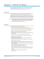
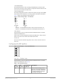
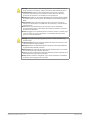
Workflow
The OG-X-FR frame comes standard with Ethernet connectivity for basic
configuration and monitoring of openGear® cards through the DashBoard control
system. An optional advanced networking card, the MFC-OG3-N, adds an on-
board Gigabit Ethernet switch, with GigE access to each of the 20 processing card
slots.
NOTE: Gigabit Ethernet is only available with the MFC-OG3-N installed in the OG-X-FR
frame.
Figure 1. Workflow of the OG-X-FR
PS2 PS1
ETHERNET
SLOT 20
SLOT 17
SLOT 13
SLOT 9
SLOT 5
SLOT 4
SLOT 1
FAN CTRL
REF 1
REF 2
+12V, -7.5V
REF 1
REF 1
REF 2
1
F
EF
RE
R
2
2
F
EF
RE
R
GFC-8322
SLOT 2
SLOT 3
SLOT 6
SLOT 7
SLOT 8
SLOT 10
SLOT 11
SLOT 12
SLOT 14
SLOT 15
SLOT 16
SLOT 18
SLOT 19
CAN BUS
x20

OG-X-FR openGear Frame v1.0r1 9 www.aja.com
Chapter 3 – Hardware Overview
Your OG-X-FR frame is a 2RU modular frame, designed to accommodate
openGear cards. A complete list of available openGear cards is available on our
website.
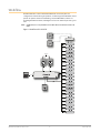
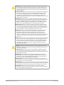
Front Panel Overview
This section briefly summarizes the features of the OG-X-FR front panel.
Figure 2. OG-X-FR Front Panel
1. Diagnostic Panel
The Diagnostic Panel is located on the frame front panel and enables you to
quickly monitor the frame. Information is presented in two separate lines of text:
• The top line in the display cycles through the name assigned to the frame
in DashBoard and the current IP address of the frame (or 0.0.0.0 if none
available). The IP address is congured on the MFC-OG3-N Network Controller
Card. Refer to the user guide for your card to learn more about setting the IP
address and frame name in DashBoard.
• The second line reports errors or alarm conditions from any source. This
includes fan failure alarms, power supply warnings, or errors reported by the
cards installed in the frame. The Diagnostic Panel organizes the messages
starting with the most recent at the top of the list. Refer to the user guide for
your openGear card to learn more about the types of error conditions that
your card reports.
2. Toggle Button
The Toggle button is located directly to the left of the Diagnostic Panel and
enables you to mute the audio alarm, or quickly scroll through the error messages
reported on the second line of the Diagnostic Panel.
• Pressing the Toggle button once mutes the audio alarm.
• Pressing the Toggle button multiple times scrolls through the messages.
NOTE: If you are scrolling through the list and a new error condition is reported, the list is
automatically updated and returns you to the beginning of the list.
3. Door Tabs
These tabs enable you to open the frame door and gain access to the interior
of the frame. An alarm is raised when the frame door is opened longer than 5
minutes.
4. Frame Glow
This feature is a user-programmable frame glow that can be configured to glow a
preset color, or customized colors to indicate different alarms. This is also useful
when trying to locate the frame within a rack room. Refer to the MFC-OG3-N and
MFC-8322-S User Guide for details on configuring this feature.

OG-X-FR openGear Frame v1.0r1 10 www.aja.com
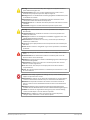
OG-X-FR Interior
This section briefly summarizes the features of the interior of the OG-X-FR chassis.
Figure 3. OG-X-FR — Interior Features with Door Removed
21
67$7
21
67$7
1. Power Supplies
The OG-X-FR frame can accommodate two front-loaded power supplies.
However, each frame comes standard with one power supply (the power supply
on the left in Figure 3.2). Although a single power supply can fully power a loaded
frame, the addition of a second (optional) power supply gives the frame full
power redundancy. Each power supply is fed by a separate power cord, which is
held in position to guard against accidental power loss.
2. GFC-8322
The GFC-8322 comes pre-installed in the designated slot immediately to the
right of PS1, and is secured with a metal retaining latch. Its primary function is to
distribute the reference signals to openGear cards installed in the frame. Refer to
the section "GFC-8322 Overview" on page 20 for more information.
3. Card Slots
There are a total of 20 card slots in the OG-X-FR chassis and are used to install
openGear cards into the chassis. Depending on the card model and rear module
you are using, multiple slots may be required. Refer to the user guide for your
openGear card for installation details for your card.
4. Controller Card
There are two models of Controller Card: MFC-8322-S and the MFC-OG3-N. The
Controller Card comes pre-installed in the OG-X-FR frame. You must have the
MFC-OG3-N installed in the OG-X-FR frame to take advantage of the Gigabit
ethernet connectivity available for openGear cards in the frame. Refer to the
MFC-OG3-N User Guide for more information.
5. Mounted Fans (not shown)
The OG-X-FR frames were designed with front-door mounted fans to provide
forced air cooling for all cards, and additional cooling for the power supplies. An
intelligent fan controller adjusts fan speed with changes in frame power loading.
Particular attention has been paid to frame acoustics in order to keep fan noise to
a minimum.
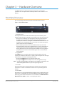
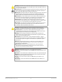
Rear Panel Overview
This section briefly summarizes the features of the OG-X-FR rear panel.

OG-X-FR openGear Frame v1.0r1 11 www.aja.com
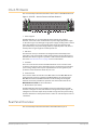
Figure 4. OG-X-FR — Rear Panel
36
9a+]:
&$87,215,6.2)6+2&.
'212723(1
5()
/223
5()
/223
36
(7+(51(7
9a+]:
&$87,21
5,6.2)6+2&.
'212723(1
2*;)5
1. PS1 Power Supply Connector
This connector is the AC Connector for the main power supply. Refer to the
section "Connecting to a Power Supply" on page 16 for more information.
2. PS2 Power Supply Connector
This connector is the AC Connector for the redundant power supply.
3. ETHERNET Communication Port
The Ethernet port is an RJ45 connector is used to connect the optional Network
Controller card to an external Ethernet network. This Network Controller card is
required to bridge the external Ethernet network to the local communication bus
for monitoring and control of cards installed in the frame. Only cards with the
Communication bus interface will be able to be monitored and controlled this
way.
NOTE: The Ethernet port does not provide Power-over-Ethernet (PoE).
4. REF Connectors
Two sets of looping BNC inputs are provided to accept two independent
reference signals supporting the following reference signal types: Analog black,
Tri-level sync, and AES/DARS reference.
5. Rear Modules for openGear Cards
The OG-X-FR frame supports module-dependent rear modules. Rear modules
can be ordered with cards, and are easy and quick to install. Blank plates must be
installed if the slots are not populated with openGear cards and rear modules.
openGear Rear Modules
If your OG-X-FR frame was ordered with cards requiring full rear modules or split
rear modules, the appropriate modules are installed at the factory or included
with the cards.
Supports DFR-8321 and OG3-FR Rear Modules
The OG-X-FR frame supports all existing rear modules designed for the DFR-8321
and OG3-FR frames. However, rear modules designed for use in the OG-X-FR
frame are not compatible with other openGear frames.
Identifying an OG-X-FR Rear Module
There are two ways to identify an OG-X-FR frame rear module:
• the notched top of the rear module, and
• a small notch on the bottom left corner of the rear module that ts into a
second seating slot on the midplane of the OG-X-FR frames. Note that this
small notch is not present on other frame rear module types.

OG-X-FR openGear Frame v1.0r1 12 www.aja.com
Caution! Attempting to install an OG-X-FR frame rear module into an OG3-FR,
DFR-8321, DFR-8320, or DFR-8310 frame can damage the rear module.
Rear Module Types
This section provides an overview of the rear module types for your OG-X-FR
frame.
Full Rear Modules
The full rear modules features a single card connector and can include a
combination of BNC, WECO™, fiber optic, serial, and ethernet connectors. Each
module occupies two slots in the frame and accommodates one card. Ensure the
openGear card is installed in the correct slot in the OG-X-FR frame. Up to 10 cards
can be installed in a frame when using these modules.
Split Rear Modules
Much like the modules for the OG3-FR frames, split modules for the OG-X-FR
frame features two card connectors and can have a combination of BNC, WECO™,
fiber optic, serial, and ethernet connectors. Each card connector is routed to a
column of five BNCs. A split rear module occupies two slots in the OG-X-FR frame
but provides connectors for two openGear cards, allowing you to install up to 20
cards in the frame.
Blank Rear Modules
Blank Rear Modules (R2-BLANK) are used when the slot does not have an
openGear card installed. This helps to ensure proper frame cooling and
ventilation.

OG-X-FR openGear Frame v1.0r1 13 www.aja.com
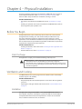
Chapter 4 – Physical Installation
If you have questions pertaining to the installation of OG-X-FR, please contact us
at the numbers listed in the section "Contacting AJA Support" on page 2. Our
technical staff is always available for consultation, training, or service.
For More Information on...
• the technical specications for the OG-X-FR, refer to "Specications" on page
44.
• installing an openGear card and its rear module in the OG-X-FR frame, refer to
the user guide for your openGear card.
Before You Begin
The OG-X-FR mounts in the rack frame by means of four rack screws fastened
through the front mounting ears. This should normally be sufficient to carry
the load, including the weight of accompanying cables. However, in certain
applications such as mobile truck installations, it may be desirable to also support
the rear of the frame. The optional Rear Support Bars and Brackets are specifically
engineered to compensate for extra load stress.
For More Information on...
• installing the brackets, refer to the section "Installing the Rear Support Bars and
Brackets" on page 14.
• the frame dimensions, refer to "Specications" on page 44.
Static Discharge
Throughout this chapter, please heed the following cautionary note:
ESD Susceptibility — Static discharge can cause serious damage to sensitive
semiconductor devices. Avoid handling circuit boards in high static
environments such as carpeted areas and when synthetic ber clothing is worn.
Always exercise proper grounding precautions when working on circuit boards
and related equipment.
Ventilation and Cooling
Your OG-X-FR frame was specially engineered to minimize internal heat buildup
and thus improve card reliability.
For More Information on...
• the power dissipation of individual openGear cards, refer to the user guide for
your card.
• replacing the cooling fan module, refer to the section "Fan Filter Maintenance"
on page 39.
Ventilation
For applications using less than 40W in a non-ventilated OG-X-FR, but where
the individual card power consumption is greater than 8W, the cards should be
evenly distributed in the frame. This will prevent the creation of concentrated
heat, or unbalanced heat-rise areas, in the frame.

OG-X-FR openGear Frame v1.0r1 14 www.aja.com
IMPORTANT: For reliable performance, it is recommended that the OG-X-FR frame door
not be opened for longer than 5 minutes on frames loaded with more than 40W.
For some extra high power cards, the door should not be open for more than 1
minute.
Cooling Fan Module
The OG-X-FR frames come standard with a Cooling Fan Module installed in the
frame door. The frame and PS-OGX can supply up to a maximum of 500W of
card power, with 15W per card. Under these ventilated conditions, there is no
requirement for extra vertical spacing between the frames. The OG-X-FR frames
can be stacked one on top of the other, a feature that is highly desirable in
densely crowded rack frame environments.
Caution! The two sides of the OG-X-FR frame have perforations that are needed to
ventilate the power supplies and must not be blocked.
Airflow Requirements
Under some conditions, the ambient air temperature inside rack-mount cabinets
can be greater that the ambient temperature within a room. For safe long term
reliability, ensure the ambient air temperatures at the OG-X-FR frame front intake
area are within the product’s specified operating temperature range. Adequate
ventilation within a rack frame must also be maintained. Ensure to adhere to the
following clearance recommendations:
• Minimum 2” (5.08cm) clearance both right and left-hand side of the chassis
sides with unrestricted vertical airow.
• Minimum 5” (12.7cm) clearance at the chassis rear with unrestricted vertical
airow.
Installation Requirements
Keep the following in mind when installing your OG-X-FR frame:
• Install the frame for maximum stability during operation and in such a way as
to allow adequate ventilation.
• The frame cannot be sealed in a closed container and must be installed in free
air space where the ambient temperature is monitored and controlled to not
exceed 40°C (104°F) at the frame front door airow intake.
• Ensure that adequate space exists in front and behind the frame and on both
sides of the frame for airow exhaust.
• The location of the frame should be accessible, dry, and dust-free.
Installing the Rear Support Bars and Brackets
Under normal conditions, mounting the OG-X-FR frame to the front of the rack
with four rack screws should be sufficient to carry the load, including the weight
of accompanying cables.
To help reduce mechanical stress due to cable weight, the FSB-OGX rear support
brackets are available for the OG-X-FR frame. The FSB-OGX are specifically
engineered to compensate for extra load stress associated with certain
applications, such as mobile truck installations, to also support the rear of the
OG-X-FR frame.

OG-X-FR openGear Frame v1.0r1 15 www.aja.com
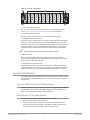
Installing the FSB-OGX
This section describes how to attach the FSB-OGX rear support bars to a OG-X-FR
frame.
NOTE: The FSB-OGX cannot be installed on the DFR-8321 or DFR-8310 frames.
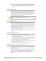
To install the FSB-OGX
1. Attach the Rack Mount Arms of the FSB-OGX to the OG-X-FR frame.
Rack Mount
Arm
Unlocked
Locked
PS2
ETHERNET
100-240V~50-60Hz 600W
CAUTION
RISK OF SHOCK
DO NOT OPEN
REF 1
LOOP
REF 2
LOOP
PS1
100-240V~50-60Hz 600W
CAUTION: RISK OF SHOCK
DO NOT OPEN
!
OGX-FR
!
!
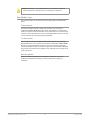
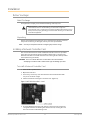
2. Install the Rail Guides for each Rack Mount Arm.
INPUTS
1 2 3 4 5
PSL
GPIO
TALLY
PS 2PS 1
LTC
6 7
Rail Guide
Retaining
Bolts
Rack Mount
Arm
PS2
ETHERNET
100-240V~47-63Hz 450W
CAUTION
RISK OF SHOCK
DO NOT OPEN
!!
REF 1
LOOP
REF 2
LOOP
PS1
100-240V~50-60Hz 600W
CAUTION: RISK OF SHOCK
DO NOT OPEN
!
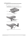
3. Secure the Rail Guides and Rack Mount Arms to the rack.
INPUTS
1 2 3 4 5
GPIO
TALLY
PS 2PS 1
LTC
6 7
5/16 Hex
Nuts
PS2
ETHERNET
100-240V~47-63Hz 450W
CAUTION
RISK OF SHOCK
DO NOT OPEN
!
!
REF 1
LOOP
REF 2
LOOP
PS1
100-240V~50-60Hz 600W
CAUTION: RISK OF SHOCK
DO NOT OPEN
!
4. Use the provided Threaded Rubber Bumpers to lock the Rack Mount Arms
in place.

OG-X-FR openGear Frame v1.0r1 16 www.aja.com
INPUTS
1 2 3 4 5
GPIO
TALLY
PS 2PS 1
LTC
6 7
Threaded
Rubber
Bumpers
PS2
ETHERNET
100-240V~47-63Hz 450W
CAUTION
RISK OF SHOCK
DO NOT OPEN
!!
REF 1
LOOP
REF 2
LOOP
PS1
100-240V~50-60Hz 600W
CAUTION: RISK OF SHOCK
DO NOT OPEN
!
Connecting to a Power Supply
The OG-X-FR comes standard with one power supply, with a second optional
power supply (OG-X-PS) available for redundancy. For redundancy, and in
applications where the equipment is used in a critical signal path, we recommend
that two power supplies be used in the OG-X-FR. One A/C power cable has been
provided with each power supply ordered.
For further redundancy, each power cord should be connected to a separate
power source for protection against failure of the A/C power circuit. In the event
of one power supply failure, the frame load is seamlessly transferred to the other
redundant power supply. Although the power supply is “hot-swappable” turning
the power supply off before inserting or removing it from the frame will increase
the life span of the connectors.
Power Supply Connectors (PSU1, PSU2)
There are two power supply connectors located on the back of the OG-X-FR:
• PSU1 — This connector is designated as the AC Connector for the rst power
supply.
• PSU2 — This connector is designated as the AC Connector for the second
power supply.
Where the connectors are located is dependent on the frame you are using.
For More Information on...
• power supply locations in your OG-X-FR, refer to the section "Rear Panel
Overview" on page 10.
• installing the PS-OGX, refer to the section "Installing a Frame Power Supply" on
page 39.
Power Cable Connection
This section includes information for connecting the power cables for the
OG-X-FR frame.
Warning Hazardous Voltages — The safe operation of this product requires that
a protective earth connection be provided. This protective earth is provided by
the grounding conductor in the equipment's supply cord. To reduce the risk of
electrical shock to operator and service personnel, this ground conductor must
be connected to an earthed ground.
Warning — In some countries, it may be necessary to supply the correct mains
supply cord. Use only an approved IEC 320 C-13 type A/C line cord rated for a
minimum 10A at 250V and certied for the country of use.

OG-X-FR openGear Frame v1.0r1 17 www.aja.com
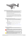
To connect the power cables for an OG-X-FR
1. Connect the cable’s female IEC connector to the frame socket marked PS 1.
2. If the Redundant Power Supply option is installed, plug the second IEC
connector into PS 2.
36
9a+]:
&$87,215,6.2)6+2&.
'212723(1
5()
/223
5()
/223
36
(7+(51(7
9a+]:
&$87,21
5,6.2)6+2&.
'212723(1
2*;)5
7R5HGXQGDQW3RZHU6XSSO\ 7R0DLQ3RZHU6XSSO\
NOTE: Each AC connector includes a PowerLock, which is designed to retain the power
cable connector.
3. Clip the PowerLock over the shoulder of the inserted AC cable end.
4. Connect the supplied power cable's three-prong male connector to an AC
outlet.

OG-X-FR openGear Frame v1.0r1 18 www.aja.com
Chapter 5 – Ethernet Cabling
The exact steps for connecting to your facility via an ethernet network depends
on the network requirements of your facility. Contact your IT Department before
connecting to your facility network to ensure that there are no conflicts.
NOTE: DashBoard uses the open SLP protocol to locate openGear frames on the
network.
For More Information on...
• conguring the Network Controller card, refer to its user guide.
• installing and using DashBoard, refer to the DashBoard User Manual.
• the specications for the OG-X-FR, refer to "Specications" on page 44.
Cabling the Ethernet Port on the OG-X-FR Frame
The Ethernet port is a standard 10/100/1000 RJ45 Ethernet connector and is used
to exchange information with an external monitoring, or control, system over an
ethernet network. You must have the MFC-OG3-N installed in the OG-X-FR to take
advantage of the Gigabit ethernet connectivity available for cards in the OG-X-FR
frame.
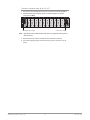
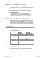
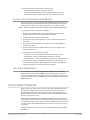
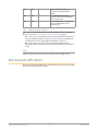
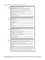
Required Pinouts
The Ethernet port has its RJ45 connector wired as a Network Interface Card
(NIC). Table 5.1 provides the wiring information based on the type of Network
Controller card installed in the OG-X-FR frame.
Table 1. Ethernet Port Pinouts
Pin Number
MFC-8322-S
(10/100 Signal)
MFC-OG3-N
(10/100/1000 Signal)
1 Tx+ TD1+
2 Tx- TD1-
3 Rx+ TD2+
4 * TD3+
5 * TD3-
6 Rx- TD2-
7 * TD4+
8 * TD4-
* Shorted, 75ohm to Ground
Connecting to a Network
Use up to 328ft (100m) of CAT6 cable or better for Gigabit Ethernet network or
use up to 328ft (100m) of CAT5 cable or better for 10/100Mbit Ethernet networks.

OG-X-FR openGear Frame v1.0r1 19 www.aja.com
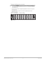
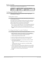
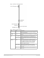
To connect the Ethernet port to a network
NOTE: Connect the ETHERNET (RJ-45) port to the same network as your DashBoard
client computer or to a network that has a route to the network your DashBoard
client computer is on.
1. Connect one free end of a straight through CAT5/5e/6 cable to a free port of
the network hub.
2. Connect the other end of the same cable to the Ethernet port on the
OG-X-FR rear panel.
Figure 5. OG-X-FR Frame — Ethernet Cabling
36
9a+]:
&$87,215,6.2)6+2&.
'212723(1
5()
/223
5()
/223
36
(7+(51(7
9a+]:
&$87,21
5,6.2)6+2&.
'212723(1
7R(WKHUQHW1HWZRUN
2*;)5

OG-X-FR openGear Frame v1.0r1 20 www.aja.com
Chapter 6 – Reference Cabling
The OG-X-FR frame includes two independent looping reference BNCs (REF
1, REF 2) with connection to each card slot. Each REF BNC accepts a single
composite or tri-level sync signal to feed timing information to the openGear
cards installed in the frame.
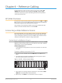
GFC-8322 Overview
The GFC-8322 receives the analog reference signals driven to the REF 1 and REF 2
BNCs located on the rear panel of OG-X-FR frame. The GFC-8322 then distributes
both reference signals to each of the 20 slots in the frame.
Frame settings such as the frame IP address, frame name, and the frame serial
number are stored on the GFC-8322 via its Serial EEPROM.
Connecting a Video Reference Source
This feature distributes one or two reference signals to all cards in the OG-X-FR
frame. Cards which need an external reference use this master reference signal
in place of taking the signal from one of the card BNCs. This provides for ease of
installation and reduction in reference cabling requirements.
Connecting to a Reference Source
If only one reference type is required for the OG-X-FR frame, connect it to the REF
1 BNC. Two reference types enables you to use reference sources with a different
signal formats, each via a separate REF BNC.
For More Information on...
• on specifying the analog reference source for your openGear card, refer to its
user guide.
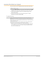
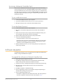
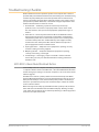
To connect a reference source to the OG-X-FR
1. Connect one end of a Belden cable to the REF 1 BNC on the OG-X-FR rear
panel.
2. Connect the other end of the same Belden cable to the applicable output
port on the external reference source device.
Figure 6. OG-X-FR — Reference Input Cabling
36
9a+]:
&$87,215,6.2)6+2&.
'212723(1
5()
/223
5()
/223
36
(7+(51(7
9a+]:
&$87,21
5,6.2)6+2&.
'212723(1
2*;)5
7R5HIHUHQFH6RXUFH
7R5HIHUHQFH6RXUFH
3. If the reference is not being looped to another device, ensure that the REF 1
LOOP BNC is terminated with a 75ohm terminator.
4. Repeat steps 1-3 for REF 2 if a second reference source is required.
La pagina si sta caricando...
La pagina si sta caricando...
La pagina si sta caricando...
La pagina si sta caricando...
La pagina si sta caricando...
La pagina si sta caricando...
La pagina si sta caricando...
La pagina si sta caricando...
La pagina si sta caricando...
La pagina si sta caricando...
La pagina si sta caricando...
La pagina si sta caricando...
La pagina si sta caricando...
La pagina si sta caricando...
La pagina si sta caricando...
La pagina si sta caricando...
La pagina si sta caricando...
La pagina si sta caricando...
La pagina si sta caricando...
La pagina si sta caricando...
La pagina si sta caricando...
La pagina si sta caricando...
La pagina si sta caricando...
La pagina si sta caricando...
La pagina si sta caricando...
La pagina si sta caricando...
La pagina si sta caricando...
La pagina si sta caricando...
La pagina si sta caricando...
La pagina si sta caricando...
La pagina si sta caricando...
La pagina si sta caricando...
La pagina si sta caricando...
La pagina si sta caricando...
La pagina si sta caricando...
La pagina si sta caricando...
-
 1
1
-
 2
2
-
 3
3
-
 4
4
-
 5
5
-
 6
6
-
 7
7
-
 8
8
-
 9
9
-
 10
10
-
 11
11
-
 12
12
-
 13
13
-
 14
14
-
 15
15
-
 16
16
-
 17
17
-
 18
18
-
 19
19
-
 20
20
-
 21
21
-
 22
22
-
 23
23
-
 24
24
-
 25
25
-
 26
26
-
 27
27
-
 28
28
-
 29
29
-
 30
30
-
 31
31
-
 32
32
-
 33
33
-
 34
34
-
 35
35
-
 36
36
-
 37
37
-
 38
38
-
 39
39
-
 40
40
-
 41
41
-
 42
42
-
 43
43
-
 44
44
-
 45
45
-
 46
46
-
 47
47
-
 48
48
-
 49
49
-
 50
50
-
 51
51
-
 52
52
-
 53
53
-
 54
54
-
 55
55
-
 56
56


AJA OG-X-FR Manuale utente
- Categoria
- Apparecchiature musicali supplementari
- Tipo
- Manuale utente
in altre lingue
- English: AJA OG-X-FR User manual
- Deutsch: AJA OG-X-FR Benutzerhandbuch
Documenti correlati
Altri documenti
-
 Eedomus eedomus+ Manuale utente
-
 ZyXEL Communications ZoneDAS Manuale utente
-
Legrand CM2002 Guida d'installazione
-
Bosch Appliances Appliances Home Security System LTC 8540/00 Manuale utente
-
WECO 14K3 RACK HV XP Manuale del proprietario
-
IFM DN4234 Guida d'installazione
-
-
IDEAL STANDARD U8594 Manuale utente
-
Thinklogical Q-4300 Manuale utente
-

