Snell Advanced Media IQMIX26 Manuale utente
- Tipo
- Manuale utente


IQMIX25/26/40/41 Information and Notices
Issue 1 Rev 4 Page 2 © 2017 SAM
Information and Notices
Copyright and Disclaimer
Copyright protection claimed includes all forms and matters of copyrightable material and
information now allowed by statutory or judicial law or hereinafter granted, including without
limitation, material generated from the software programs which are displayed on the screen
such as icons, screen display looks etc.
Information in this manual and software are subject to change without notice and does not
represent a commitment on the part of SAM. The software described in this manual is
furnished under a license agreement and can not be reproduced or copied in any manner
without prior agreement with SAM or their authorized agents.
Reproduction or disassembly of embedded computer programs or algorithms prohibited.
No part of this publication can be transmitted or reproduced in any form or by any means,
electronic or mechanical, including photocopy, recording or any information storage and
retrieval system, without permission being granted, in writing, by the publishers or their
authorized agents.
SAM operates a policy of continuous improvement and development. SAM reserves the right
to make changes and improvements to any of the products described in this document
without prior notice.
Contact Details
Customer Support
For details of our Regional Customer Support Offices please visit the SAM website and
navigate to Support/24/7 Support Contact Details.
www.s-a-m.com/support/247-support/
Customers with a support contract should call their personalized number, which can be found
in their contract, and be ready to provide their contract number and details.

IQMIX25/26/40/41 Safety Information
Issue 1 Rev 4 Page 3 © 2017 SAM
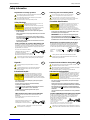
Safety Information
Explanation of Safety Symbols
This symbol refers the user to important information contained in
the accompanying literature. Refer to manual.
This symbol indicates that hazardous voltages are present inside.
No user serviceable parts inside.
This unit should only be serviced by trained personnel.
Servicing instructions where given, are for use by
qualified service personnel only.
To reduce risk of electric shock do not perform any
servicing other than that contained in the operating
instructions unless you are qualified to do so.
Refer all servicing to qualified personnel.
· To reduce the risk of electric shock, do not expose this appliance
to rain or moisture.
· Always ensure that the unit is properly earthed and power connections
correctly made.
· This equipment must be supplied from a power system providing a
PROTECTIVE EARTH connection and having a neutral connection
which can be reliably identified.
· The power outlet supplying power to the unit should be close to the
unit and easily accessible
Power connection in countries other than the USA
The equipment is normally shipped with a power cable with a standard IEC
moulded free socket on one end and a standard IEC moulded plug on the other.
If you are required to remove the moulded mains supply plug, dispose of the
plug immediately in a safe manner.
The colour code for the lead is as follows:
GREEN/YELLOW lead connected to E
(Protective Earth Conductor)
BLUE lead connected to N (Neutral Conductor)
BROWN lead connected to L (Live Conductor)
Caution If the unit has two mains supply inputs ensure that both power
cords are plugged into mains outlets operating from the same phase.
LN
E
NL
E
GB
!
CAUTION
RISK OF ELECTRIC SHOCK
DO NOT REMOVE COVERS
NO USER SERVICEABLE PARTS
REFER SERVICING TO QUALIFIED
PERSONNEL ONLY
!
!
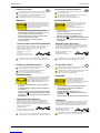
Safety Warnings
Erklärung der Sicherheitssymbole
Dieses Symbol weist den Benutzer auf wichtige Informationen
hin, die in der begleitenden Dokumentation enthalten sind.
Dieses Symbol zeigt an, dass gefährliche Spannung vorhanden ist.
Es befinden sich keine vom Benutzer zu wartenden Teile im Geräteinneren.
Dieses Gerät sollte nur von geschultem Personal gewartet werden
· Um das Risiko eines Elektroschocks zu reduzieren, setzen Sie das
Gerät weder Regen noch Feuchtigkeit aus.
· Stellen Sie immer sicher, dass das Gerät ordnungsgemäß geerdet
und verkabelt ist.
· Dieses Equipment muss an eine Netzsteckdose mit Schutzleiter
angeschlossen werden und einen zuverlässig identifizierbaren Nullleiter haben.
· Die Netzsteckdose sollte nahe beim Gerät und einfach zugänglich sein.
Netzanschluss in anderen Ländern als der USA
Das Equipment wird im Normalfall mit einem Netzkabel mit Standard IEC
Anschlussbuchse und einem Standard IEC Anschlussstecker geliefert.
Sollten Sie den angeschweißten Stecker auswechseln müssen, entsorgen
Sie diesen bitte umgehend. Die farbliche Belegung des Netzkabels ist wie folgt:
GRÜN GELB E = Schutzleiter
BLAU N = Nulleiter
BRAUN L = P = Phase
Achtung: Wenn das Gerät zwei Anschlussbuchsen hat, stellen
Sie bitte sicher, dass beide Netzkabel mit der selben Phase in die
Netzsteckdose gesteckt werden.
Sicherheits-Warnhinweise
D
!
!
Die angeführten Service-/Reparatur-Anweisungen sind
ausschließlich von qualifiziertem Service-Personal
auszuführen. Um das Risiko eines lektroschocks zu
reduzieren, führen Sie ausschließlich die im
Benutzerhandbuch eschriebenen Anweisungen aus,
es sei denn, Sie haben die entsprechende Qualifikation.
Wenden Sie sich in allen Service-Fragen an qualifiziertes Personal.
!
ACHTUNG
Gefahr von Elektroschocks.
Abdeckungen nicht entfernen
Keine vom Benutzer zu wartende Teile
Wenden Sie sich ausschließlich
an qualifiziertes Personal
L=
Phase N=
Nulleiter N=
Nulleiter L=
Phase
E=
Schutzleiter E=
Schutzleiter
Légende :
Ce symbole indique qu'il faut prêter attention et se référer
au manuel.
Ce symbole indique qu'il peut y avoir des tensions électriques
à l'intérieur de l'appareil. Ne pas intervenir sans l'agrément
du service qualifié.
·Pour réduire le risque de choc électrique, ne pas exposer l'appareil
dans un milieu humide.
·Toujours s'assurer que l'unité est correctement alimentée,
en particuliers à la liaison à la terre.
·La source électrique de cet équipement doit posséder une connexion
à la terre , ainsi qu'une liaison « neutre » identifiable.
·La prise électrique qui alimente l'appareil doit être proche
de celle-ci et accessible.
Câble secteur de pays autres que les Etats-Unis
L'équipement est livré avec un câble secteur au standard IEC, moulé
mâle/femelle.
Si vous souhaitez changr la prise mâle de votre cordon, voici les
codes couleurs des fils :
Le fil VERT/JAUNE est connecté à T (Terre)
Le fil BLEU est connecté à N (Neutre)
Le fil MARRON est connecté à P (Phase)
Attention si l'appareil a 2 alimentations, s'assurer que les cordons
soient branchés sur la même phase.
Précaution d'emploi :
F
Les procédures de maintenance ne concernent
que le service agréé. Afin de réduire le risque de
choc électrique, il est recommandé de se limiter
aux procédures d'utilisation, à moins d'en être qualifié.
Pour toute maintenance, contacter le service compétent.
!
ATTENTION
RISQUE DE CHOC ELECTRIQUE
NE PAS RETIRER LE COUVERCLE
NE PAS INTERVENIR SANS
L'AGREMENT DU SERVICE
QUALIFIE
PN
T
NP
T
Connecteur Prise
!
!
Explicación de los Símbolos de Seguridad
Éste símbolo refiere al usuario información importante contenida
en la literatura incluida. Referirse al manual.
Éste símbolo indica que voltajes peligrosos están presentes en el interior.
No hay elementos accesibles al usuario dentro.
Esta unidad sólo debería ser tratada por personal cualificado.
Las instrucciones de servicio cuando sean dadas, son
sólo para uso de personal cualificado. Para reducir el
riesgo de choque eléctrico no llevar a cabo ninguna
operación de servicio aparte de las contenidas en las
instrucciones de operación, a menos que se esté
cualificado para realizarlas.
Referir todo el trabajo de servicio a personal cualificado.
· Para reducir el riesgo de choque eléctrico, no exponer este equipo
a la lluvia o humedad.
· Siempre asegurarse de que la unidad está propiamente conectada a
tierra y que las conexiones de alimentación están hechas correctamente.
· Este equipo debe ser alimentado desde un sistema de alimentación
con conexión a TIERRA y teniendo una conexión neutra fácilmente
identificable.
· La toma de alimentación para la unidad debe ser cercana y fácilmente
accesible.
Conexión de alimentación en otros países que no sean USA
El equipo es normalmente entregado con un cable de alimentación con un
enchufe hembra estándar IEC en un extremo y con una clavija estándar
IEC en el otro. Si se requiere eliminar la clavija para sustituirla por otra,
disponer dicha clavija de una forma segura.
El código de color a emplear es como sigue:
Advertencia Si la unidad tuviera dos tomas de alimentación, asegurarse
de que ambos cables de alimentación están conectados a la misma fase.
ESP
!
!
Advertencias de Seguridad
LN
E
NL
E
Clavija
Aerea Macho Enchufe
Aereo Hembra
VERDE/ AMARILLO conectado a E
(Conductor de protección a Tierra
-Earth en el original-)
AZUL conectado a N (Conductor Neutro -Neutral en el original-)
MARRÓN conectado a L (Conductor Fase -Live en el original-)
RIESGO DE CHOQUE ELECTRICO
NO QUITAR LAS PROTECCIONNES
ELEMENTOS NO ACCESIBLES AL
USUARIO.
SERVICIO SOLAMENTE A PERSONAL
CUALIFICADO

IQMIX25/26/40/41 Safety Information
Issue 1 Rev 4 Page 4 © 2017 SAM
Simboli di sicurezza:
Questo simbolo indica l'informazione importante contenuta nei
manuali appartenenti all'apparecchiatura. Consultare il manuale.
Questo simbolo indica che all'interno dell'apparato sono presenti
tensioni pericolose. Non cercare di smontare l'unità.
Per qualsiasi tipo di intervento rivolgersi al personale qualificato.
Le istruzioni relative alla manutenzione sono ad uso
esclusivo del personale qualificato. E' proibito all'utente
eseguire qualsiasi operazione non esplicitamente
consentita nelle istruzioni. Per qualsiasi informazione
rivolgersi al personale qualificato.
· Per prevenire il pericolo di scosse elettriche è necessario non esporre
mai l'apparecchiatura alla pioggia o a qualsiasi tipo di umidità.
· Assicurarsi sempre, che l'unità sia propriamente messa a terra e che
le connessioni elettriche siano eseguite correttamente.
· Questo dispositivo deve essere collegato ad un impianto elettrico
dotato di un sistema di messa a terra efficace.
· La presa di corrente deve essere vicina all'apparecchio
e facilmente accessibile.
Connessione elettrica nei paesi diversi dagli Stati Uniti
L'apparecchiatura normalmente è spedita con cavo pressofuso con la presa
e spina standard IEC. Nel caso della rimozione della spina elettrica,
gettarla via immediatamente osservando tutte le precauzioni del caso.
La leggenda dei cavi è la seguente:
VERDE/GIALLO cavo connesso
ad "E" (terra)
BLU cavo connesso ad "N" (neutro)
MARRONE cavo connesso ad "L" ( fase)
Attenzione! Nel caso in cui l'apparecchio abbia due prese di corrente,
assicurarsi che i cavi non siano collegati a fasi diverse della rete elettrica.
I
!
!
Attenzione:
!
ATTENZIONE
LN
E
NL
E
Presa volante Spina volante
RISCHIO DI SHOCK ELETTRICO
NON CERCARE DI SMONTARE
L'UNITA PER QUALSIASI TIPO DI
INTERVENTO RIVOLGERSI AL
PERSONALE QUALIFICATO
Forklaring på sikkerhedssymboler
Dette symbol gør brugeren opmærksom på vigtig information
i den medfølgende manual.
Dette symbol indikerer farlig spænding inden i apparatet. Ingen bruger
servicerbare dele i apparatet på brugerniveau.
Dette apparat må kun serviceres af faglærte personer..
Serviceinstruktioner er kun til brug for faglærte
servicefolk. For at reducere risikoen for elektrisk
stød må bruger kun udføre anvisninger i
betjeningsmanualen.
Al service skal udføres af faglærte personer.
· For at reducere risikoen for elektrisk stød må apparatet ikke
udsættes for regn eller fugt.
· Sørg altid for at apparatet er korrekt tilsluttet og jordet.
· Dette apparat skal forbindes til en nettilslutning, der yder
BESKYTTENDE JORD og 0 forbindelse skal være tydeligt markeret.
· Stikkontakten, som forsyner apparatet, skal være tæt på apparatet
og let tilgængelig.
Nettilslutning i andre lande end USA
Udstyret leveres normalt med et strømkabel med et standard IEC støbt løst
hunstik i den ene ende og et standard IEC støbt hanstik i den anden ende.
Hvis et af de støbte stik på strømkablet er defekt, skal det straks kasseres på
forsvarlig vis. Farvekoden for lederen er som følger:
GRØN/GUL leder forbundet til J (Jord)
BLÅ leder forbundet til 0
BRUN leder forbundet til F(Fase)
Forsigtig Hvis enheden har to lysnetindgange, skal der sørges for at
begge ledninger tilsluttes lystnetudgange fra den samme fase.
DK
!
!
!
Sikkerhedsadvarsler
!
FORSIGTIG
RISIKO FOR ELEKTRISK STØD
DÆKPLADER MÅ IKKE FJERNES
INGEN BRUGER SERVICERBARE
DELE SERVICE MÅ KUN UDFØRES
AF FAGLÆRTE PERSONER
F0
J
0F
J
Han-stik Hun-stik
Förklaring av Säkerhetssymboler
Denna symbol hänvisar användaren till viktig information som
återfinns i litteraturen som medföljer. Se manualen.
Denna symbol indikerar att livsfarlig spänning finns på insidan.
Det finns inga servicevänliga delar inne i apparaten.
Denna apparat få endast repareras av utbildad personal.
Serviceinstruktioner som anges avser endast kvalificerad
och utbildad servicepersonal. För att minska risken för
elektrisk stöt, utför ingen annan service än den som
återfinns i medföljande driftinstruktionerna, om du ej är
behörig. Överlåt all service till kvalificerad personal.
· För att reducera risken för elektrisk stöt, utsätt inte apparaten för
regn eller fukt.
· Se alltid till att apparaten är ordentligt jordad samt att strömtillförseln
är korrekt utförd.
· Denna apparat måste bli försörjd från ett strömsystem som är försedd
med jordadanslutning samt ha en neutral anslutning som lätt identifierbar.
· Vägguttaget som strömförsörjer apparaten bör finnas i närheten samt
vara lätttillgänglig.
Strömkontakter i länder utanför USA
Apparaten utrustas normalt med en strömkabel med standard IEC gjuten
honkontakt på ena änden samt en standard IEC gjuten hankontakt på den
andra änden. Om man måste avlägsna den gjutna hankontkaten, avyttra
denna kontakt omedelbart på ett säkert sätt. Färgkoden för ledningen är följande:
GRÖN/GUL ledning ansluten till E
(Skyddsjordad ledare)
BLÅ ledning ansluten till N (Neutral ledare)
BRUN ledning ansluten till L (Fas ledare)
Varning! Om enheten har två huvudsakliga elförsörjningar, säkerställ att
båda strömkablarna som är inkopplade i enheten arbetar från samma fas.
S
!
CAUTION
RISK OF ELECTRIC SHOCK
DO NOT REMOVE COVERS
NO USER SERVICEABLE PARTS
REFER SERVICING TO QUALIFIED
PERSONNEL ONLY
!
!
Säkerhetsvarningar
LN
E
NL
E
Stickkontakt-Hane Stickkontakt-Hona
Turvamerkkien selitys
Tämä merkki tarkoittaa, että laitteen mukana toimitettu kirjallinen
materiaali sisältää tärkeitä tietoja. Lue käyttöohje.
Tämä merkki ilmoittaa, että laitteen sisällä on vaarallisen voimakas jännite.
Sisäpuolella ei ole mitään osia, joita käyttäjä voisi itse huoltaa.
Huollon saa suorittaa vain alan ammattilainen.
Huolto-ohjeet on tarkoitettu ainoastaan alan
ammattilaisille. Älä suorita laitteelle muita
toimenpiteitä, kuin mitä käyttöohjeissa on
neuvottu, ellet ole asiantuntija. Voit saada sähköiskun.
Jätä kaikki huoltotoimet ammattilaiselle.
· Sähköiskujen välttämiseksi suojaa laite sateelta ja kosteudelta.
· Varmistu, että laite on asianmukaisesti maadoitettu ja että
sähkökytkennät on tehty oikein.
· Laitteelle tehoa syöttävässä järjestelmässä tulee olla
SUOJAMAALIITÄNTÄ ja nollaliitännän on oltava luotettavasti
tunnistettavissa.
· Sähköpistorasian tulee olla laitteen lähellä ja helposti tavoitettavissa.
Sähkökytkentä
Laitteen vakiovarusteena on sähköjohto, jonka toisessa päässä on muottiin
valettu, IEC-standardin mukainen liitäntärasia ja toisessa päässä muottiin
valettu, IEC-standardin mukainen pistoliitin. Jos pistoliitin tarvitsee poistaa,
se tulee hävittää heti turvallisella tavalla. Johtimet kytketään seuraavasti:
KELTA-VIHREÄ suojamaajohdin E-napaan
SININEN nollajohdin N-napaan
RUSKEA vaihejohdin L-napaan
Huom! Jos laitteessa on kaksi verkkojännitteen tuloliitäntää, niiden johdot
on liitettävä verkkopistorasioihin, joissa on sama vaiheistus.
FI
!
!
Turvaohjeita
!
SÄHKÖISKUN VAARA ÄLÄ AVAA
LAITTEEN KANSIA EI SISÄLLÄ
KÄYTTÄJÄLLE HUOLLETTAVIA
OSIA HUOLTO AINOASTAAN
AMMATTILAISEN SUORITTAMANA
VAROITUS
LN
E
NL
E
Pistoliitin Liitäntärasia

IQMIX25/26/40/41 Safety Information
Issue 1 Rev 4 Page 5 © 2017 SAM
Laser Safety
This product operates with Class 1 laser products.
Ventilation
Although the unit is constructed to meet normal environmental requirements, ensure that
there is a free flow of air at the front, rear, and sides of the unit to dissipate the heat produced
during operation. Installations should be designed to allow for this.
Safety Standards
This equipment conforms to the following standards:
EN60950-1 2006
Safety of Information Technology Equipment Including
Electrical Business Equipment.
UL1419 (3rd Edition) - UL File E193966
Standard for Safety – Professional Video and Audio equipment.
Símbolos de Segurança
O símbolo triangular adverte para a necessidade de consultar o
manual antes de utilizar o equipamento ou efectuar qualquer ajuste.
Este símbolo indica a presença de voltagens perigosas no interior
do equipamento. As peças ou partes existentes no interior do equipamento
não necessitam de intervenção, manutenção ou manuseamento por parte
do utilizador. Reparações ou outras intervenções devem ser efectuadas
apenas por técnicos devidamente habilitados.
As instruções de manutenção fornecidas são para
utilização de técnicos qualificados. Para reduzir o
risco de choque eléctrico, não devem ser realizadas
intervenções no equipamento não especificadas no
manual de instalações a menos que seja efectuadas
por técnicos habilitados.
· Para reduzir o risco de choque eléctrico, não expor este equipamento
à chuva ou humidade.
· Assegurar que a unidade está sempre devidamente ligada à terra e
que as ligações à alimentação estão correctas.
· O sistema de alimentação do equipamento deve, por razões de
segurança, possuir ligação a terra de protecção e ligação ao
NEUTRO devidamente identificada.
· A tomada de energia à qual a unidade está ligada deve situar-se na
sua proximidade e facilmente acessível.
Ligação da alimentação noutros países que não os EUA
O equipamento é, normalmente, enviado com cabo de alimentação com ficha
IEC fêmea standard num extremo e uma ficha IEC macho standard no extremo
oposto. Se for necessário substituir ou alterar alguma destas fichas, deverá
remove-la e elimina-la imediatamente de maneira segura.
O código de cor para os condutores é o seguinte:
Condutor VERDE/AMARELO ligado a E (Terra)
Condutor AZUL ligado a N (Neutro)
Condutor CASTANHO ligado a L (Vivo).
Atenção: Se a unidade tem duas fontes de alimentação assegurar que os
dois cabos de alimentação estão ligados a tomadas pertencentes à mesma fase.
P
!
!
Avisos de Segurança
LN
E
NL
E
Ficha Livre Tomada Livre
!
CAUTION
RISK OF ELECTRIC SHOCK
DO NOT REMOVE COVERS
NO USER SERVICEABLE PARTS
REFER SERVICING TO QUALIFIED
PERSONNEL ONLY
Caution: Use of controls or adjustments or performance of procedures other than those
specified herein may result in hazardous radiation exposure.
Do not obstruct the ventilation holes on the right-side of the unit. Damage to the equipment
may result.

IQMIX25/26/40/41 Safety Information
Issue 1 Rev 4 Page 6 © 2017 SAM
EMC Standards
This equipment conforms to the following standards:
EN 55032:2012 (Class A)
Electromagnetic Compatibility of Multimedia Equipment - Emission Requirements.
EN 61000-3-2:2014 (Class A)
Limits for Harmonic Current Emissions.
EN 61000-3-3:2013
Limitation of Voltage Changes, Voltage Fluctuations and Flicker in Public Low-Voltage Supply
Systems.
FCC/CFR 47:Part 15, Class A
Federal Communications Commission Rules Part 15, Subpart B, Class A.
EMC Environment
The product(s) described in this manual conform to the EMC requirements for, and are
intended for use in, the controlled EMC environment (for example, purpose-built broadcasting
or recording studios), and the rural outdoor environment (far away from railways, transmitters,
overhead power lines, etc.) E4.
EMC Performance of Cables and Connectors
SAM products are designed to meet or exceed the requirements of the appropriate European
EMC standards. In order to achieve this performance in real installations it is essential to use
cables and connectors with good EMC characteristics.
All signal connections (including remote control connections) shall be made with screened
cables terminated in connectors having a metal shell. The cable screen shall have a
large-area contact with the metal shell.
Coaxial Cables
Coaxial cables connections (particularly serial digital video connections) shall be made with
high-quality double-screened coaxial cables such as Belden 1694 or BBC type PSF1/2M.
D-type Connectors
D-type connectors shall have metal shells making good RF contact with the cable screen.
Connectors having indents which improve contact between the plug and socket shells are
recommended.
Warning: This equipment is compliant with Class A of CISPR
32. In a residential environment this equipment may cause radio
interference.

IQMIX25/26/40/41 Contents
Issue 1 Rev 4 Page 7 © 2017 SAM
Contents
Information and Notices . . . . . . . . . . . . . . . . . . . . . . . . . . . . . . . . . . . . . . . . . . . . . . . . 2
Safety Information . . . . . . . . . . . . . . . . . . . . . . . . . . . . . . . . . . . . . . . . . . . . . . . . . . . . . 3
1 Introduction . . . . . . . . . . . . . . . . . . . . . . . . . . . . . . . . . . . . . . . . . . . . . . . . . . . . . . . . . 9
1.1 Description . . . . . . . . . . . . . . . . . . . . . . . . . . . . . . . . . . . . . . . . . . . . . . . . . . . . . . 9
1.2 Block Diagrams. . . . . . . . . . . . . . . . . . . . . . . . . . . . . . . . . . . . . . . . . . . . . . . . . . . 9
1.2.1 IQMIX25/26. . . . . . . . . . . . . . . . . . . . . . . . . . . . . . . . . . . . . . . . . . . . . . . . . . 9
1.2.2 IQMIX40/41. . . . . . . . . . . . . . . . . . . . . . . . . . . . . . . . . . . . . . . . . . . . . . . . . 10
1.3 Order Codes . . . . . . . . . . . . . . . . . . . . . . . . . . . . . . . . . . . . . . . . . . . . . . . . . . . . 10
1.4 Rear Panel View . . . . . . . . . . . . . . . . . . . . . . . . . . . . . . . . . . . . . . . . . . . . . . . . . .11
1.5 Feature Summary . . . . . . . . . . . . . . . . . . . . . . . . . . . . . . . . . . . . . . . . . . . . . . . . 16
1.5.1 IQMIX25 3G/HD/SD-SDI Multi-channel IP Transceiver . . . . . . . . . . . . . . . 16
1.5.2 IQMIX40 3G/HD/SD-SDI Multi-channel IP Transceiver . . . . . . . . . . . . . . . 16
1.6 Enclosures. . . . . . . . . . . . . . . . . . . . . . . . . . . . . . . . . . . . . . . . . . . . . . . . . . . . . . 17
1.6.1 B-style Enclosure . . . . . . . . . . . . . . . . . . . . . . . . . . . . . . . . . . . . . . . . . . . . 17
1.6.2 IQFAN00 Cooling Fan Module . . . . . . . . . . . . . . . . . . . . . . . . . . . . . . . . . . 18
1.6.3 Fitting the Fan Module . . . . . . . . . . . . . . . . . . . . . . . . . . . . . . . . . . . . . . . . 18
2 Technical Specification. . . . . . . . . . . . . . . . . . . . . . . . . . . . . . . . . . . . . . . . . . . . . . . 19
3 Connections. . . . . . . . . . . . . . . . . . . . . . . . . . . . . . . . . . . . . . . . . . . . . . . . . . . . . . . . 21
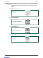
3.1 SDI BNC Input/Outputs. . . . . . . . . . . . . . . . . . . . . . . . . . . . . . . . . . . . . . . . . . . . 21
3.2 10/25G Ethernet SFP . . . . . . . . . . . . . . . . . . . . . . . . . . . . . . . . . . . . . . . . . . . . . 21
3.3 40G Ethernet QSFP . . . . . . . . . . . . . . . . . . . . . . . . . . . . . . . . . . . . . . . . . . . . . . 21
3.4 DensiShield. . . . . . . . . . . . . . . . . . . . . . . . . . . . . . . . . . . . . . . . . . . . . . . . . . . . . 21
4 Card Edge LEDs . . . . . . . . . . . . . . . . . . . . . . . . . . . . . . . . . . . . . . . . . . . . . . . . . . . . 22
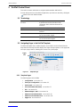
5 RollCall Control Panel. . . . . . . . . . . . . . . . . . . . . . . . . . . . . . . . . . . . . . . . . . . . . . . . 23
5.1 Terminology. . . . . . . . . . . . . . . . . . . . . . . . . . . . . . . . . . . . . . . . . . . . . . . . . . . . . 23
5.2 Navigating Pages in the RollCall Template . . . . . . . . . . . . . . . . . . . . . . . . . . . . . 23
5.2.1 Template Pages . . . . . . . . . . . . . . . . . . . . . . . . . . . . . . . . . . . . . . . . . . . . . 23
5.2.2 Setting Values . . . . . . . . . . . . . . . . . . . . . . . . . . . . . . . . . . . . . . . . . . . . . . . 24
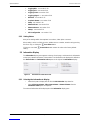
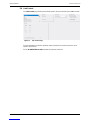
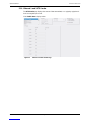
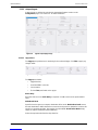
5.3 Information Display . . . . . . . . . . . . . . . . . . . . . . . . . . . . . . . . . . . . . . . . . . . . . . . 24
5.3.1 Selecting the Information to Display . . . . . . . . . . . . . . . . . . . . . . . . . . . . . . 24
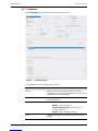
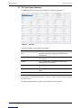
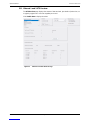
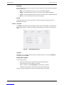
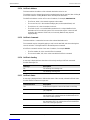
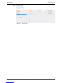
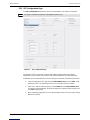
5.4 Configuration. . . . . . . . . . . . . . . . . . . . . . . . . . . . . . . . . . . . . . . . . . . . . . . . . . . . 25
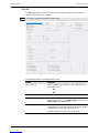
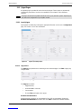
5.5 Time Sync Configuration. . . . . . . . . . . . . . . . . . . . . . . . . . . . . . . . . . . . . . . . . . . 27
5.5.1 Status . . . . . . . . . . . . . . . . . . . . . . . . . . . . . . . . . . . . . . . . . . . . . . . . . . . . . 28
5.5.2 Histogram . . . . . . . . . . . . . . . . . . . . . . . . . . . . . . . . . . . . . . . . . . . . . . . . . . 28
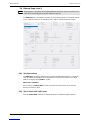
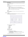
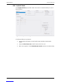
5.6 Link Control. . . . . . . . . . . . . . . . . . . . . . . . . . . . . . . . . . . . . . . . . . . . . . . . . . . . . 29
5.7 TPG (Test Pattern Generator). . . . . . . . . . . . . . . . . . . . . . . . . . . . . . . . . . . . . . . 30
5.8 FEC. . . . . . . . . . . . . . . . . . . . . . . . . . . . . . . . . . . . . . . . . . . . . . . . . . . . . . . . . . . 31
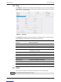
5.9 Ethernet Pages 1 and 2. . . . . . . . . . . . . . . . . . . . . . . . . . . . . . . . . . . . . . . . . . . . 33
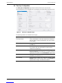
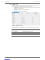
5.9.1 The Ethernet Pane . . . . . . . . . . . . . . . . . . . . . . . . . . . . . . . . . . . . . . . . . . . 33
5.9.2 The All Traffic/CPU Traffic Panes . . . . . . . . . . . . . . . . . . . . . . . . . . . . . . . . 33
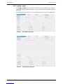
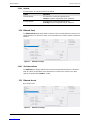
5.10 Ethernet 1 and 2 RTP Sender. . . . . . . . . . . . . . . . . . . . . . . . . . . . . . . . . . . . . . 34
5.11 Ethernet 1 and 2 RTP Receiver. . . . . . . . . . . . . . . . . . . . . . . . . . . . . . . . . . . . . 35
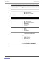
5.12 Spigot Pages. . . . . . . . . . . . . . . . . . . . . . . . . . . . . . . . . . . . . . . . . . . . . . . . . . . 36
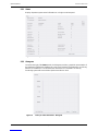
5.12.1 Input Spigots . . . . . . . . . . . . . . . . . . . . . . . . . . . . . . . . . . . . . . . . . . . . . . . 36
5.12.2 Output Spigots. . . . . . . . . . . . . . . . . . . . . . . . . . . . . . . . . . . . . . . . . . . . . . 38
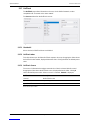
5.13 Logging - Misc. . . . . . . . . . . . . . . . . . . . . . . . . . . . . . . . . . . . . . . . . . . . . . . . . . 40
5.14 Logging - SFP . . . . . . . . . . . . . . . . . . . . . . . . . . . . . . . . . . . . . . . . . . . . . . . . . . 44
5.15 Logging - FPGA. . . . . . . . . . . . . . . . . . . . . . . . . . . . . . . . . . . . . . . . . . . . . . . . . 46
5.16 Logging - Spigot . . . . . . . . . . . . . . . . . . . . . . . . . . . . . . . . . . . . . . . . . . . . . . . . 47
5.17 RollTrack . . . . . . . . . . . . . . . . . . . . . . . . . . . . . . . . . . . . . . . . . . . . . . . . . . . . . . 49
5.17.1 Disable All . . . . . . . . . . . . . . . . . . . . . . . . . . . . . . . . . . . . . . . . . . . . . . . . . 49
5.17.2 RollTrack Index . . . . . . . . . . . . . . . . . . . . . . . . . . . . . . . . . . . . . . . . . . . . . 49

IQMIX25/26/40/41 Contents
Issue 1 Rev 4 Page 8 © 2017 SAM
5.17.3 RollTrack Source. . . . . . . . . . . . . . . . . . . . . . . . . . . . . . . . . . . . . . . . . . . . 49
5.17.4 RollTrack Address. . . . . . . . . . . . . . . . . . . . . . . . . . . . . . . . . . . . . . . . . . . 50
5.17.5 RollTrack Command . . . . . . . . . . . . . . . . . . . . . . . . . . . . . . . . . . . . . . . . . 50
5.17.6 RollTrack Sending. . . . . . . . . . . . . . . . . . . . . . . . . . . . . . . . . . . . . . . . . . . 50
5.17.7 RollTrack Status . . . . . . . . . . . . . . . . . . . . . . . . . . . . . . . . . . . . . . . . . . . . 50
5.18 Loopback Router. . . . . . . . . . . . . . . . . . . . . . . . . . . . . . . . . . . . . . . . . . . . . . . . 51
5.19 Setup. . . . . . . . . . . . . . . . . . . . . . . . . . . . . . . . . . . . . . . . . . . . . . . . . . . . . . . . . 52
5.19.1 Restart. . . . . . . . . . . . . . . . . . . . . . . . . . . . . . . . . . . . . . . . . . . . . . . . . . . . 52
5.19.2 Defaults. . . . . . . . . . . . . . . . . . . . . . . . . . . . . . . . . . . . . . . . . . . . . . . . . . . 53
5.20 Ethernet Front . . . . . . . . . . . . . . . . . . . . . . . . . . . . . . . . . . . . . . . . . . . . . . . . . . 53
5.20.1 The Ethernet Pane . . . . . . . . . . . . . . . . . . . . . . . . . . . . . . . . . . . . . . . . . . 53
5.21 Ethernet Arcnet . . . . . . . . . . . . . . . . . . . . . . . . . . . . . . . . . . . . . . . . . . . . . . . . . 53
5.22 Interop Page . . . . . . . . . . . . . . . . . . . . . . . . . . . . . . . . . . . . . . . . . . . . . . . . . . . 54
5.23 SFP Configuration Page . . . . . . . . . . . . . . . . . . . . . . . . . . . . . . . . . . . . . . . . . . 55

IQMIX25/26/40/41 Introduction
Issue 1 Rev 4 Page 9 © 2017 SAM
1 Introduction
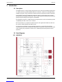
1.1 Description
The IQMIX series is a range of multi-channel video over IP transceiver modules developed for
use within low latency, high bandwidth Ethernet IP networks, capable of encoding/decoding
multiple SDI signals. They provide both compressed and uncompressed modes of operation.
Using SMPTE 2042 (VC2) lightweight compression allows for high quality signal carriage
whilst optimizing bandwidth requirements, while sending signals uncompressed provides best
quality transport although at the expense of bandwidth.
Encapsulation of signals in a SMPTE 2022-6 transport stream can also be handled to provide
compatibility with other video over IP solutions.
RFC417 provides for uncompressed video transport, and supports RFC3190 for Audio and
the yet-to-be ratified Edwards standard for data.
At a physical level, HD-BNC and DensiShield connectors are catered for. DensiShield
connectors allow the cards to be partnered with SAM's IP expansion cards for the Sirius S800
router, allowing easy integration of video over IP networking with existing SDI base band
operations.
1.2 Block Diagrams
1.2.1 IQMIX25/26

IQMIX25/26/40/41 Introduction
Issue 1 Rev 4 Page 10 © 2017 SAM
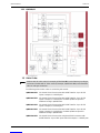
1.2.2 IQMIX40/41
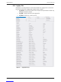
1.3 Order Codes
The following product order codes are covered by this manual:
Note:
Modules with "B" order codes (for example, IQFDA3100-1B3) can be fitted only into B-type
enclosures. Modules with "A" order codes (for example, IQFDA3100-1A3) can be fitted into
either A- or B-type enclosures.
IQMIX4000-2B3 16 channel SDI to IP transceiver with 40GbE interface. Up to 16 SDI
inputs or outputs, 2 x 40GbE ports.
IQMIX4001-3B3 16 channel SDI to IP transceiver with 40GbE interface. Up to 16 SDI
inputs or outputs, 2 x 40GbE ports. Includes IQFAN rear panel for
additional cooling in IQH3B frame.
IQMIX4010-2B3 16 channel SDI to IP transceiver with 10GbE interface. Up to 16 SDI
inputs or outputs, 2 x 10GbE ports.
IQMIX4011-3B3 16 channel SDI to IP transceiver with 10GbE interface. Up to 16 SDI
inputs or outputs, 2 x 10GbE ports. Includes IQFAN rear panel for
additional cooling in IQH3B frame.
IQMIX4100-2B3 16 channel SDI to IP transceiver using DensiShield connectors with
40GbE interface. Up to 8 SDI inputs and 8 SDI outputs, 2 x 40GbE ports.

IQMIX25/26/40/41 Introduction
Issue 1 Rev 4 Page 11 © 2017 SAM
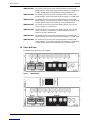
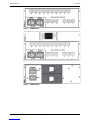
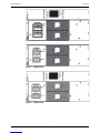
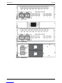
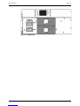
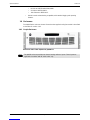
1.4 Rear Panel View
The following rear panel types are available:
IQMIX4101-3B3 16 channel SDI to IP transceiver using DensiShield connectors with
40GbE interface. Up to 8 SDI inputs and 8 SDI outputs, 2 x 40GbE ports.
Includes IQFAN rear panel for additional cooling in IQH3B frame.
IQMIX4110-2B3 16 channel SDI to IP transceiver using DensiShield connectors with
10GbE interface. Up to 8 SDI inputs and 8 SDI outputs, 2 x 10GbE ports.
IQMIX4111-3B3 16 channel SDI to IP transceiver using DensiShield connectors with
10GbE interface. Up to 8 SDI inputs and 8 SDI outputs, 2 x 10GbE ports.
Includes IQFAN rear panel for additional cooling in IQH3B frame.
IQMIX2500-2B3 16 channel SDI to IP transceiver with 25GbE interface. Up to 16 SDI
inputs or outputs, 2 x 25GbE ports.
IQMIX2501-3B3 16 channel SDI to IP transceiver with 25GbE interface. Up to 16 SDI
inputs or outputs, 2 x 25GbE ports. Includes IQFAN rear panel for
additional cooling in IQH3B frame.
IQMIX2600-2B3 16 channel SDI to IP transceiver using DensiShield connectors with
25GbE interface. Up to 8 SDI inputs and 8 SDI outputs, 2 x 25GbE ports.
IQMIX2601-3B3 16 channel SDI to IP transceiver using DensiShield connectors with
25GbE interface. Up to 8 SDI inputs and 8 SDI outputs, 2 x 25GbE ports.
Includes IQFAN rear panel for additional cooling in IQH3B frame.
Figure 1 IQMIX4000-2B3
Figure 2 IQMIX4001-3B3


IQMIX25/26/40/41 Introduction
Issue 1 Rev 4 Page 16 © 2017 SAM
1.5 Feature Summary
1.5.1 IQMIX25 3G/HD/SD-SDI Multi-channel IP Transceiver
• Handles up to 16 SDI signals over dual 10GbE or25GbE IP links (dependent on SDI
signal format and compressed/uncompressed transport mode).
• Supports configuration of Ethernet links for maximum signal transport using both
SFPs, or for dual link mode to provide link redundancy as per SMPTE 2022-7.
• Multiple transport types available for each SDI input, including:
• Compressed IP transport using SMPTE-2042 (VC2) low latency high quality
encoding profile.
• Uncompressed video transport using either RFC 4175 RTP or SMPTE-2022-6
encapsulation.
• PCM audio using RFC 3190 & AES67
• SMPTE-291M metadata support via IETF standard RTP Payload for Ancillary
Data.
• Timing and synchronization provided by IEEE-1588v2 (PTP), compliant with
SMPTE-2059-2, or via the IQH3B frame analog reference bus.
• Supports unicast as well as IGMPv3 source-specific multicast, allowing point to point
operation or transmission in multicast groups.
• Standards supported:
• 3G-SDI to SMPTE 424M/425M level A compatible.
• HD-SDI to SMPTE292M/274M/296M.
• SD-SDI to SMPTE259M-C.
• 10G Ethernet to IEEE 802.3.
• Rollcall control and monitoring compatible, with standard logging and reporting
features.
1.5.2 IQMIX40 3G/HD/SD-SDI Multi-channel IP Transceiver
• Handles up to 16 SDI signals over dual 10GbE or dual 40GbE IP links (dependent on
Ethernet rate, SDI signal format and compressed/uncompressed transport mode).
• Supports configuration of Ethernet links for maximum signal transport using both
SFPs, or for dual link mode to provide link redundancy as per SMPTE 2022-7.
• Multiple transport types available for each SDI input, including:
• Compressed IP transport using SMPTE-2042 (VC2) low latency high quality
encoding profile.
• Uncompressed video transport using either RFC 4175 RTP or SMPTE-2022-6
encapsulation.
• PCM audio using RFC 3190 & AES67.
• SMPTE-291M metadata support via IETF standard RTP Payload for Ancillary
Data.
• Timing and synchronization provided by IEEE-1588v2 (PTP), compliant with
SMPTE-2059-2, or via the IQH3B frame analog reference bus.
• Supports unicast as well as IGMPv3 source-specific multicast, allowing point to point
operation or transmission in multicast groups.
• Standards supported:
• UHD-SDI (4x3G-SDI)
• 3G-SDI to SMPTE 424M/425M level A/B compatible.

IQMIX25/26/40/41 Introduction
Issue 1 Rev 4 Page 17 © 2017 SAM
• HD-SDI to SMPTE292M/274M/296M.
• SD-SDI to SMPTE259M-C.
• 10G Ethernet to IEEE 802.3.
• Rollcall control and monitoring compatible, with standard logging and reporting
features.
1.6 Enclosures
The IQMIX fits the enclosure shown. Ensure that the supplied cooling fan module is also fitted
as described in section 1.6.2.
1.6.1 B-style Enclosure
Enclosure order codes: IQH3B-S-0, IQH3B-S-P
Note:
The IQH3B enclosure provides two internal analog reference inputs. These inputs are
applicable to modules with “B” order codes only.

IQMIX25/26/40/41 Introduction
Issue 1 Rev 4 Page 18 © 2017 SAM
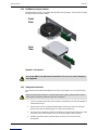
1.6.2 IQFAN00 Cooling Fan Module
IQMIX25/26/40/41 cards are supplied with IQFAN00 cooling modules. Ensure these are fitted
according to the instructions below.
IQFAN00 Cooling Module
1.6.3 Fitting the Fan Module
A fan module must be fitted immediately to the left of each IQMIX card, as viewed from the
rear.
1. Choose an empty slot position for the module, immediately to the left of the IQMIX as
viewed from the rear.
2. Remove the screws securing the blanking plate covering the chosen slot position.
Remove and store the blanking plate in a safe place for future use.
3. Ensuring correct orientation, fit the fan module rear connecting panel to the rear of the
enclosure in the vacant aperture, and secure with the fixing screws provided.
4. Reattach the power supply and start up the enclosure. The fan should start
immediately.
Front
View
Rear
View
Do not run IQMIX cards without the fan modules. This can cause severe damage to
the equipment.
Before performing this operation, ensure that the power supply is switched OFF and the
mains power connection at the rear of the unit is removed.

IQMIX25/26/40/41 Technical Specification
Issue 1 Rev 4 Page 19 © 2017 SAM
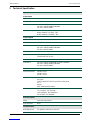
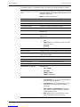
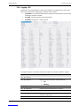
2 Technical Specification
Inputs/Outputs
Signal Inputs
Inputs Up to 16 (0/4/8/12/16)
Connector/Format BNC/75R
Conforms to 3G-SDI to SMPTE 424M/425M level A compatible
HD-SDI to SMPTE292M/274M/296M
SD-SDI to SMPTE259M-C
Input cable length Belden 1694A @ 3 Gbit/s - TBC
Belden 1694A @ 1.5 Gbit/s - TBC
Belden 1694A @ 270 Mbit/s - TBC
Signal Outputs
Outputs Up to 16 (16/12/8/4/0)
Connector/Format BNC/75R
Conforms to 3G-SDI to SMPTE 424M/425M level A/B compatible
HD-SDI to SMPTE292M/274M/296M
SD-SDI to SMPTE259M-C
DensiShield
Inputs 2:0/1:1/0:2 (DensiShield connectors In:Out)
16:0/0:16/8:8 (SDI In:Out)
Connector/Format DensiShield pair
Conforms to 3G-SDI to SMPTE 424M/425M level A/B compatible
HD-SDI to SMPTE292M/274M/296M
SD-SDI to SMPTE259M-C
Ethernet
Connector/Format 10GbE = SFP+
25GbE = SFP+
40GbE = QSFP
Conforms to RFC4175
RFC3190
SMPTE-291M /IETF RTP Payload for Ancillary Data
VC-2
AES'67
IEEE-1588v2/SMPTE-2059-2
Video Standards 1125 (1080)/50p (A), 1125 (1080)/59p (A),
750 (720)/50p, 750 (720)/59p,
1125 (1080)/25i, 1125 (1080)/29i,
625 (576)/25i, 525 (480)/29i
RollCall Features
Status Input and Output status
User memories None
Communication
RollCall/RollCall+ Via gateway or directly via rear SFP

IQMIX25/26/40/41 Technical Specification
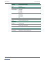
Issue 1 Rev 4 Page 20 © 2017 SAM
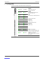
Indicators Front Panel and Card Edge
Power OK (Green)
CPU OK (Green flashing)
1-12 Input standard
detection LEDs UHD (White)
3G (Green)
HD (Green)
SD (Yellow)
None (Red)
Logging Input Status
Input Alarms
Output Alarms
Output Status
Misc
RollTrack controls On/off, Index, Source, Address, Command, Status, Sending
Setup Versions, reset defaults, restart
Specifications
Electrical Transport Stream
Connector/Format HD-BNC
Standard SAM screw terminal
Start-up Time
Power Consumption
Module Power
Consumption IQMIX25/26 34.5 PR Max (B frame only)
IQMIX40/41 37.5 PR Max (B frame only)
La pagina si sta caricando...
La pagina si sta caricando...
La pagina si sta caricando...
La pagina si sta caricando...
La pagina si sta caricando...
La pagina si sta caricando...
La pagina si sta caricando...
La pagina si sta caricando...
La pagina si sta caricando...
La pagina si sta caricando...
La pagina si sta caricando...
La pagina si sta caricando...
La pagina si sta caricando...
La pagina si sta caricando...
La pagina si sta caricando...
La pagina si sta caricando...
La pagina si sta caricando...
La pagina si sta caricando...
La pagina si sta caricando...
La pagina si sta caricando...
La pagina si sta caricando...
La pagina si sta caricando...
La pagina si sta caricando...
La pagina si sta caricando...
La pagina si sta caricando...
La pagina si sta caricando...
La pagina si sta caricando...
La pagina si sta caricando...
La pagina si sta caricando...
La pagina si sta caricando...
La pagina si sta caricando...
La pagina si sta caricando...
La pagina si sta caricando...
La pagina si sta caricando...
La pagina si sta caricando...
-
 1
1
-
 2
2
-
 3
3
-
 4
4
-
 5
5
-
 6
6
-
 7
7
-
 8
8
-
 9
9
-
 10
10
-
 11
11
-
 12
12
-
 13
13
-
 14
14
-
 15
15
-
 16
16
-
 17
17
-
 18
18
-
 19
19
-
 20
20
-
 21
21
-
 22
22
-
 23
23
-
 24
24
-
 25
25
-
 26
26
-
 27
27
-
 28
28
-
 29
29
-
 30
30
-
 31
31
-
 32
32
-
 33
33
-
 34
34
-
 35
35
-
 36
36
-
 37
37
-
 38
38
-
 39
39
-
 40
40
-
 41
41
-
 42
42
-
 43
43
-
 44
44
-
 45
45
-
 46
46
-
 47
47
-
 48
48
-
 49
49
-
 50
50
-
 51
51
-
 52
52
-
 53
53
-
 54
54
-
 55
55


Snell Advanced Media IQMIX26 Manuale utente
- Tipo
- Manuale utente
in altre lingue
Documenti correlati
Altri documenti
-
QNAP QSW-3216R-8S8T Quick Installation Guide
-
 Snell & Wilcox TBS100 Manuale utente
-
-
AJA OG-FIBER-2T Manuale utente
-
AJA HDR Image Analyzer Manuale utente
-
AJA FiDO-4T Manuale utente
-
AJA FiDO-2R-12G Manuale utente
-
AJA Hi5-12G Manuale utente
-
Mellanox Technologies MSX1024B-2BFS Manuale utente
-
