
INSTRUCTION FOR USE
NÁVOD K POUŽITÍ
BEDIENUNGSANLEITUNG
ISTRUZIONI PER L'USO
GEBRUIKSAANWIJZING
GCE VALVES
PRESSURE REGULATORS INTEGRATED
WITH CYLINDER VALVES EN
MediVital®E
REDUKČNÍ VENTILY S INTEGROVANÝM
UZAVÍRACÍM VENTILEM PLYNOVÝCH LAHVÍ CS
DRUCKREGLER MIT FLASCHENVENTILEN DE
REGOLATORI DI PRESSIONE
CON VALVOLA DELLA BOMBOLA INTEGRATA IT
NL
DRUKREGELAARS MET GEÏNTEGREERDE
CILINDERKLEPPEN

2/92
EN
1. FOREWORD
The product complies with the essential requirements of 93/42/EEC Medical Device Directive
and Transportable Pressure Equipment Directive 2010/35 EU. The combination valve is
designed according to EN ISO 10524-3 and EN ISO 10297 standards.
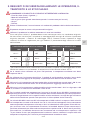
TERM MEANING
MEDIVITAL®E Combination valve MediVital®E is equipped with an electronic pressure
indicator E-GAUGE
EGAUGE Electronic indicator
DISPLAY Electronical indication device
2. INTENDED USE
MediVital®E Combination Valves are designed to be fi tted to gas cylinders used for medical
gases. These combination valves together with a gas cylinder form gas packages used either
as gas supply point for medical devices (anaesthetic devices, ventilating devices, incubators
etc.) or for direct gas supply to a patient’s breathing mask or cannula.
GCE Combination Valves are intended to be used with the following medical gases:
• Oxygen
• Nitrous oxide
• Air for breathing
• Helium
• Carbon dioxide
• Mixtures of the gases listed above.
MediVital®E combination valve is not intended for use with fl ammable anaesthetics and
substances.
2.1. PATIENT PROFILE
Medivital®E supplies medical gas by means of the control fl ow head in fl ow range from 0 to 15
(25) l/min.
Saturation of the medical gas must be prescribed by the doctor or an anaesthetic nurse who
has got the medical education, assessed the heath status of the patient and supplies him with
required amount of the medical gas.
Health status - the assesment and decision about the use timing and dosage amount
requirements of the patient is up to the doctor or medical personnel.
Medical personnel - nurse, rescuer, paramedic or carer who has obtained medical education.
2.2. USER PROFILE
Use in the hospital or ambulance:
• Education: personnel with medical education
Home care use:
Therapy is prescribed by a doctor or personnel who has got a medical education in the fi eld of
breathing support:
• Knowledge: training of personnel with medical education who has got an ability to read, train
and apply knowledge from the instruction for use.
Training must be performed according to regulations valid in each country.
Important:
Patient must be trained by the doctor or person who has got an education in the life saving.
ENGLISH
INSTRUCTION FOR USE: MEDIVITAL®E

3/92
EN
3. OPERATIONAL, TRANSPORT AND STORAGE SAFETY
REQUIREMENTS
KEEP THE PRODUCT AND ITS ASSOCIATED EQUIPMENT AWAY FROM:
• Heat sources (fi re, cigarettes,...)
• Flammable materials
• Oil or grease (take a great care in the use of hand creams)
• Water
• Dust
The product and its associated equipment must be prevented from tipping over, turning over
or falling.
Always maintain oxygen cleanliness standards.
Only use the product and its associated equipment in well ventilated area.
Before the fi rst use the product shall be kept in its original package. If removed from service
(for transport, storage) GCE recommends using the original package (including inner packing
materials). National laws, rules and regulations for medical gases, accident prevention and
environmental protection must be observed.
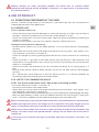
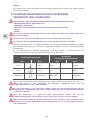
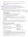
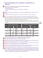
OPERATING CONDITIONS STORAGE AND TRANSPORT CONDITIONS
MIN MAX MIN MAX
-20 °C* +65 -40 °C +70 °C
10 % 100 % 10 % 100 %
600 mbar 1200 mbar 600 mbar 1200 mbar
*for inner tightness of the shut-off valve, during transport and storage of the combination valve
mounted on a cylinder, the valid lower temperature limit is -40°C.
If the valve is used in the reach of a patient, the ambient temperature must not exceed 40°C.
When used in home care, the acclimatization time after a change of conditions from storage
(or transport) to operational must be at least 1 hour.
In case of the combination valve storage temperature drops below -20°C do not use the
combination valve until its temperature reaches at least -20°C.
In case the ambient valve temperature drops below -10°C or rises above +40°C, the battery is
being self-discharged, and therefore the lifetime is shortened.
For the combination valves designed to be used with mixture of gases O2+N2O, the lowest
operating temperature is +5°C. In normal use of the combination valve, frosting can appear on
the combination valve surface, which is caused by the gas inside the combination valve when
high pressure in the combination valve cooling when high pressure gas is being reduced to
low pressure (Joule-Thomson e ect).
O2+N2O mixtures are temperature sensitive. N2O begins to separate out from the mixture if
the temperature falls below about -6°C. A homogenous mixture is again obtained when the
temperature has raised above 10°C and the cylinder was agitated. Before use, to ensure it is
properly mixed, cylinders should be stored horizontally for 24 hours at a temperature above
10°C. If this is not practicable, before use the cylinders must be maintained at a temperature
above 10°C for at least 2 hours and then completely inverted three times or placed in warm
water at body temperature for 5 minutes and then completely inverted three times.

4/92
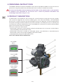
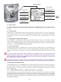
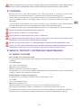
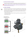
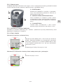
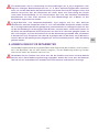
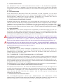
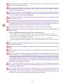
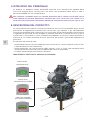
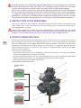
EN 5. PRODUCT DESCRIPTION
A combination valve combines the function of a shut-off valve of a high pressure gas cylinder
and a pressure regulator for use with medical gases. Gas from the cylinder is fi rst controlled
by the main shut-off valve then passed through the pressure regulator and fi nally delivered to
the patient through the fl ow outlet or the pressure outlet. The outlet pressure is fi xed by the
manufacturer and each combination valve is provided with a low-pressure relief valve to protect
against failure of the pressure regulator.
There are three basic alternatives:
• combination valve with a quick-coupler outlet, the outlet pressure is constant, and the fl ow is
not controlled by the combination valve,
• combination valve with an outlet via calibrated nozzles, the outlet fl ow is controlled by the
combination valve and can be changed by the control head,
• the combination valve with both alternatives.
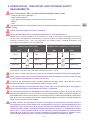
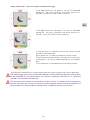
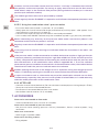
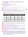
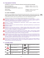
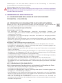
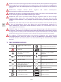
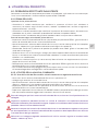
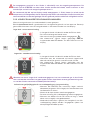
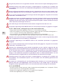
SHUT OFF VALVE STATUS INDICATOR:
4. PERSONNEL INSTRUCTIONS
The Medical Devices Directive 93/42/EEC states that the product provider must ensure that all
personnel using the product are provided with the instructions & performance data.
Do not use the product without properly familiarization of the product and its safe operation
as defi ned in this Instruction for use. Ensure user is aware of particular information and
knowledge required for the gas in use.
fully OPEN
green
fully CLOSED
red
partly OPEN
red / green

5/92
EN
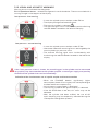
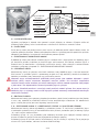
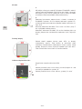
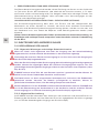
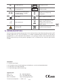
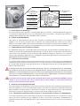
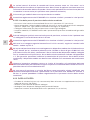
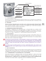
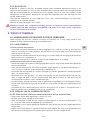
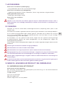
Marking detail
Inlet connection
type
Total weight
allowance of the
package
Filling port type
End of lifetime
Reference
number
Inlet pressure
Serial number
Compliance with
93/42 EEC
Compliance with
2010/35 EU
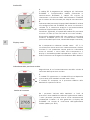
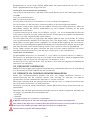
A INLET STEM
The combination valve is fi tted to a gas cylinder by a threaded inlet stem. The inlet stem can
be taper threaded or parallel threaded with diff erent sizes depending on the cylinder size and
material.
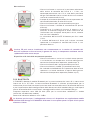
B FILLING PORT
A fi lling port is provided for fi lling the gas cylinder at a fi lling station, it has no function for
patient use. It includes a non-return valve (NRV). The NRV means that special fi lling adaptors
are required to vent gas from the cylinder during the fi lling process (venting and/or vacuuming
cylinders).
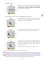
C ELECTRONIC INDICATOR EGAUGE
The E-GAUGE is intended for indicating the amount of gas inside the gas cylinder and the
remaining time of gas supply at the current fl ow. The indicator is active, i.e. the amount of gas
in cylinder is indicated regardless to shut-off valve position. More information can be found in
Chapter 5.1 - ELECTRONIC INDICATOR E-GAUGE.
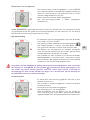
D SHUTOFF VALVE
The combination valve is provided with a shut-off valve to isolate the gas in the cylinder from
the rest of combination valve functions. It must be opened when fi lling the cylinder and patient
therapy. Part of the hand wheel is an indicator showing the open/close status of the shut-off
valve.
The shut-o valve´s open/close status indicator is for guidance only. The shut-o valve may
not be fully o when OFF status is showing. Fully closed status has to be checked by ensuring
the shut-o valve is turned fully clockwise until a fi rm resistance to the rotation is reached and
gas supply to the outlets has stopped.
The shut-o valve must not be used in the "partly ON" status because even though gas is
supplied to the outlets, the fl ow can be limited due to an insu ciently opened shut-o valve.
E RESIDUAL PRESSURE VALVE
The combination valve is equipped with a residual pressure valve with a function to retain a
minimum positive pressure in the gas cylinder to avoid contamination of the cylinder content
by atmospheric air. During cylinder gas ventilation through the fi lling port the residual pressure
valve is bypassed.
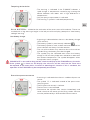
F, G FLOW CONTROL HEAD “F” AND FLOW OUTLET “G” OPTION
The combination valve can be delivered with a fl ow control head “F”.This function is used to
supply adjustable gas fl ow rates (l/min) at atmospheric pressure directly to a patient through the
fl ow outlet “G”, for instance through a cannula or a facemask. The fl ow outlet “G“ is equipped
with a hose fi tting (hose nipple) or a threaded type (for accessories to be connected using a
threaded connection).

6/92
EN
Movement of the fl ow outlet ‘G’ is normal due to the method of fi xing in the main body. It does
not indicate a faulty fl ow outlet.
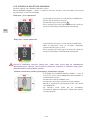
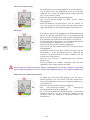
H PRESSURE OUTLET OR QUICK COUPLER OPTION
The combination valve may be fi tted with a pressure outlet. The pressure outlet is supplied with
gas direct from the low-pressure part of the combination valve and it is fi tted with a gas specifi c
medical quick coupling connector also called a “quick coupler”. The user can connect another
piece of equipment to this outlet with a gas specifi c male probe (see appendix No. 2). The quick
coupler self seals when the male probe is disconnected. This outlet is for supplying gas at a
controlled pressure to power medical devices, for instance a medical ventilator.
I PRESSURE RELIEVE VALVE OF THE LOW PRESSURE PART
The pressure relieve valve secures the low pressure part of the combination valve and
connected medical devices against over-pressure. If the gas pressure is decreased enough
after the pressure relieve valve activation, it will closes itself.
J EXCESS FLOW DEVICE OR DIP TUBE OPTION
Excess fl ow device ensures the safe ventilation of gas from the gas cylinder in case the
combination valve is broken above the inlet stem (e.g. cylinder fall). A dip tube does not have
such a function. The excess fl ow device and dip tube are to avoid contamination from the
cylinder entering the combination valve .
PRESSURE RELIEF DEVICE OF THE HIGH PRESSURE PART BURSTING DISC OPTIONAL
The high pressure relief device is intended to protect the cylinder and high pressure part of
the combination valve against damage caused by increased cylinder pressure. If the pressure
relief device has been activated, it will not reseal and the combination valve must be taken out
of service for repair (see Chapter 9).
Note: The colour of the product (especially the guard, fl ow control head and shut-o valve)
does not have to match the gas colour coding.
5.1. ELECTRONIC INDICATOR EGAUGE
5.1.1. DEVICE DESCRIPTION
5.1.1.1. General warnings and important safety information
The actual parameter of the gas pressure inside the cylinder is shown even if the valve is not
used or the quick coupler is used as an outlet.
Indication of the remaining time of gas supply is only active when the outlet from the fl ow
head is used.
At simultaneous use of fl ow head outlet and pressure outlet (quick coupler) the indicated
parameters of the remaining time of gas supply are not accurate. The manufacturer does not
recommend using both outlets simultaneously during operational mode by the manufacturer.
(see chapter 6.2.2.2.)
No parts of the E-GAUGE can be replaced / repaired by the user. In case of a defect, the
product must be sent back to the manufacturer.
The battery is only replaceable by trained service personnel. An attempt to exchange the
battery without an authorized service technician may lead to dangerous situations such as
excessive heat or fi re.
Contraindication: No known contraindication exist. The E-GAUGE is only used to monitor the
gas pressure inside the cylinder and the remaining time of gas supply (only if fl ow head outlet
is used).

7/92
EN
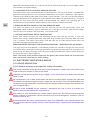
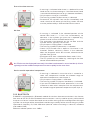
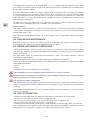
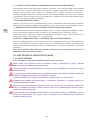
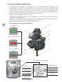
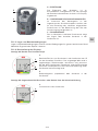
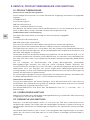
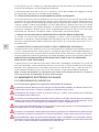
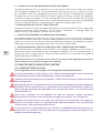
5.1.1.2. General description
The E-GAUGE is used to show information about the pressure inside the gas cylinder and about
the remaining time of the gas supply - until the complete exhaustion of gas cylinder - at the
actually set fl ow (fl ow head outlet use only).
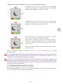
A ELECTRONICS
The electronics of the E-GAUGE is located in the
plastic guard. The LCD display is used to indicate
of the operational information.
B SENSOR OF THE FLOW CONTROL HEAD
POSITION
Inside the control unit there is an integrated
sensor of the fl ow control head position. It is
intended to detect the actual set fl ow to calculate
the time of the gas supply.
C – PRESSURE SENSOR
The pressure sensor installed in the valve port
provides a signal about the actual cylinder
pressure.
5.1.1.3. Storage and operational conditions
Storage and operational conditions are in compliance with the conditions for the complete
MediVital®E combination valve mentioned in the chapter 3.
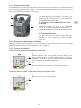
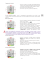
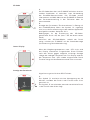
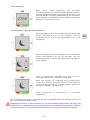
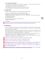
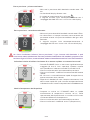
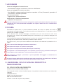
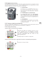
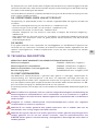
5.1.1.4. Display description
Indications during operation of the fl ow control head.
A
B
A.
Remaining time until the cylinder pressure drops to 15
bar at an actual fl ow. The indicated parameter is regularly
updated. The remaining time is automatically compensated
by the variation of ambient temperature.
B.
Bar chart equal to the pressure inside the gas cylinder.
Indications when null fl ow is set or when the quick coupler is used
A
C.
Actual pressure in the gas cylinder.
A
B
C

8/92
EN
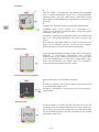
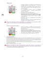
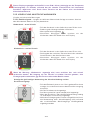
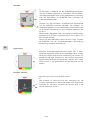
2D code
A.
The 2D code is intended for connecting the E-GAUGE
with a mobile application more easily.. Using Bluetooth
communication. The 2D code keeps information about
MAC address of E-GAUGE for fi lling stations or maintenance
purposes.
B:
Indication of "cylinder volume" parameter related to the
E-GAUGE setup. If the symbol ??L is displayed, it is
necessary to perform parameterization using the mobile
application. See par. 6.1.3
Conditions applying to the 2D code appearance: Measured
pressure < 2,5 bar (respectively 7 bar in the case of a new
valve)
Exit from the 2D code mode: As soon as the pressure
grows, the E-GAUGE switches to the standard display
(pressure measuring, remaining time calculating)
Empty display
If the ambient temperature drops below -35°C, the display
operation is terminated automatically. This function
protects against any incorrect indication of characters due
to the low temperature. The display is switched on again
when the temperature rises above -30°C. This function is
not related to the condition of the battery.
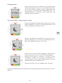
Residual pressure indication
A
Signalization of an incorrect RPV function.
A.
Symbol „R“ appears with a 30 min delay after the pressure
in cylinder drops below 2 bar.
Symbol „R“ disappears if actual pressure in the cylinder is
above 10 bar.
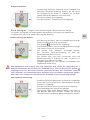
Security code
If the parameters "cylinder volume" and "pressure unit" are
modifi ed using the mobile application, the new values can
be saved by inserting the 4-digit security code generated
by the E-GAUGE display into the input fi eld in the mobile
application (see. 6.1.3).

9/92
EN
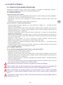
Deep sleep mode – low consumption of electrical energy
If the Medivital®E has not been in use for an extended
period (10 - 20 hours typically) and actual pressure in
cylinder is more than 15 bar at the same time.
If the Medivital®E has not been in use for an extended
period (10 - 20 hours typically) and actual pressure in
cylinder is less than 15 bar at the same time.
If zero pressure is indicated, the pre-set volume of the
cylinder is also displayed.
If the symbol ??L is visible (instead of a numeric value).
The parameter cylinder volume is not set and it is necessary
to confi gure it using the mobile application, see chapter
6.1.3.
This functionality is intended primarily for fi lling stations.
Activate the E-GAUGE by turning the fl ow head knob into any position for normal operation.
The indicated gas pressure in the cylinder depends on the ambient temperature. The function
of the E-GAUGE can be infl uenced by this feature, especially when there is a signifi cant
variation in the ambient temperature.
The remaining time shown on the display is 5-10% shorter (in relation to the temperature,
cylinder size) than the real time in which the actual cylinder content would be emptied at a
constant fl ow. This fact provides the patient with a su cient security reserve time.

10/92
EN
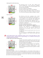
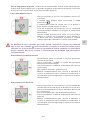
5.1.2. VISUAL AND ACOUSTIC WARNINGS
Warning alarms are divided into two groups:
5.1.2.1. Operational alarms - related to the general use of the device. These are marked with a
warning triangle in the top part of the display.
Low pressure - fi rst warning
• In case the cylinder pressure drops under 50 bar.
• The display background becomes black.
• The warning symbol is indicated
• The acoustic signal starts simultaneously with the fl ashing
red LED diodes located on the left of the display.
Low pressure - second warning
• In case the cylinder pressure drops under 15 bar.
• Information about the remaining time is exchanged by the
actual cylinder gas pressure value.
• The acoustic warning signal starts simultaneously with
the fl ashing the red LED diodes located on the left of the
display.
If the "Low pressure" alarm is shown, the remaining gas in the cylinder can be consumed
very quickly. Pay close attention to the cylinder, prepare a reserve gas supply, and possibly
discontinue the cylinder from service immediately.
Indication of the simultaneous use of a quick coupler and hose connection
• When the E-GAUGE detects signifi cantly higher
consumption (about 4 l/min higher) than corresponding to
the flow outlet consumption only.
• Only the pressure parameter is displayed
• The warning symbol of QC (quick coupler) is indicated
• If the QC outlet fl ow is too low, this status may not be
detected.
• After the cylinder had been re-fi lled, the use of QC
quick coupling may be temporarily indicated during the
subsequent cooling down process.

11/92
EN
Tempering of the device
• The warning is indicated if the E-GAUGE indicates a
rapid change in temperature caused by eg. moving the
device between two rooms with a high diff erence in
temperatures.
• Only the pressure parameter is indicated.
• The warning T symbol is indicated (temperature).
5.1.2.2. Error alarms - related to the evaluation of the error status of the device. These are
marked with a big warning triangle in the left part of the display (except the "Low battery
voltage" warning)
Low battery charge
• A warning is indicated when there is a low battery charge
(2,7V and less).
• The battery symbol is permanently indicated
• The battery symbol is static, it does not have an active bar
chart indicator and always includes one bar.
• The use of the device may continue but at the earliest
cylinder fi lling, the battery must be changed.
• The symbol may be indicated even when the battery
charge is OK, but the cylinder was moved to a room with
low ambient temperature. The symbol disappears when
the cylinder warms up again.
Error of the pressure measure
• A warning is indicated when there is a defect of pressure
sensor.
• The symbol ??? is indicated instead of the pressure or
remaining time.
• The PS (pressure sensor) is indicate.
• The bar chart is not indicated.
• Discontinue the cylinder from service immediately and
send it back to the owner of the fi lling station. Service
must be performed by a GCE certifi ed service centre.
If MediVital®E is not used for long periods, check the display of the E-GAUGE every 3 months.
If the symbol is shown on the display, the valve can still be used, but the valve must
be replaced at the latest within 3 months of detecting this situation. If this is not done, the
operation of the E-GAUGE may be unexpectedly terminated.

12/92
EN
Error of the fl ow measure
• A warning is indicated when there is a defect of the low
head sensor, its disconnecting or if the fl ow control head
is outside the defi ned position (e.g. in between two flows).
• Only the pressure value is indicated.
• The warning symbol FS (fl ow sensor) is indicated.
• Discontinue the cylinder from service immediately and
send it back to the owner of the fi lling station. Service
must be performed by a GCE certifi ed service centre.
No fl ow
• A warning is indicated if the selected position of the
control fl ow head is > 1 l/min but simultaneously no
decrease in the cylinder gas pressure is reported (e.g.
closed shut-off valve or throttled outlet hose)
• The evaluation time depends on the set fl ow and the
cylinder volume, typically 2-10 minutes.
• Only the pressure parameter is indicated.
• The warning symbol FE (fl ow error) is indicated.
• Check if the shut-off valve is open or if the hose is not
throttled. Perform necessary actions. If the indication
does not disappear within few minutes, discontinue the
cylinder from service.
• Evaluation of FE alert is blocked for fl ows under 1 l/min.
• The FE symbol can be hidden by switching of the fl ow
control head to diff erent position.
An FE alert can be displayed incorrectly if the fl ow head control is set to low fl ow (1-2 l/min
typically) and the ambient temperature increase rapidly in the same time.
Device outside operational temperature
• A warning is indicated in case the valve is moved to a
room with temperature outside the allowed range of
operational temperature, see chapter 3.
• Only the pressure parameter is indicated.
• The warning symbol TC (thermal conditions) is indicated.
• If you want the Medivital®E to be operational, it must be
moved to a room which complies with the requirements
for allowed range of operation temperature (see chpt. 3).
5.1.3. BLUETOOTH
E-GAUGE is equipped with a Bluetooth module for wireless data communication in the licence-
free zone of 2,4 to 2,5 GHz. Bluetooth communication is mainly used for primary calibration of
the pressure sensor and the fl ow head sensor and for setting up of the confi guration of the gas
cylinder size and type of the control fl ow head during assembly of the valve to the gas cylinder.
Operational frequency: 2,4 GHz ISM zone (zone for radio transmitting in industrial, academic
and medical fi eld)
Eff ective radiation power: max. 3 dBm.

13/92
EN
Maximal distance for safety connection between the device with an installed mobile
application GCE eGauge and the E-GAUGE is 10 meters in an open space. In closed spaces
this distance shortens.
6. USE OF PRODUCT
6.1. OPERATIONS PERFORMED BY THE USER
Contact a relevant fi lling station, or manufacturer if you need help with the, maintenance or
unexpected operation of the Medivital®E.
6.1.1. BEFORE USE
Visual inspection before use:
• Check the combination valve for damage (incl. label and marking). If it shows signs of external
damages, remove the product from service and suitably identify its status.
• Check the combination valve for contamination. Apply the cleaning procedure according to
chapter 8 if needed.
• Check that the cylinder´s gas pressure indicator indicates suffi cient pressure.
Leak-tight and functional test before use:
• Set fl ow control head (if any) to the ZERO position - ensure the fl ow control head engages
correctly.
• Slowly open the shut-off valve hand wheel (anticlockwise) until fully open - after approx. 1 turn
(see indication in the picture in chapter 5).
• Check for leakage by listening (leakage would be heard as the characteristic hiss of fl owing
gas).
• Check that there is a gas fl ow at each fl ow control head set position in both clockwise and
anticlockwise turning directions (for instance by sound or by checking for the presence of
bubbles in a humidifi er).
• Close the shut-off valve (clockwise). Do not use excessive torque (max. closing torque is 5
Nm).
• Reset the fl ow control head to ZERO position and ensure the fl ow control head engages
correctly.
• For a combination valve fi tted with a pressure outlet, ensure it is in working condition by
connecting and disconnecting the quick-coupler probe.
6.1.2. USE OF THE COMBINATION VALVE
6.1.2.1. Use of the combination valve´s fl ow outlet and setting the fl ow:
• Ensure the fl ow control head is in position “0”.
• Connect the accessories to the fl ow outlet.
• Slowly open the shut-off valve hand wheel (anticlockwise) until fully open - after approx. 1 turn
(see indication in the picture in chapter 5).
• Set the fl ow head to the required fl ow position. Ensure the fl ow control head engages correctly.
• After the required fl ow has been set, the E-GAUGE calculates the remaining gas supply time,
which is constantly updated and corrected according to the current fl ow rate.
Before connecting any accessory to the fl ow outlet make sure that the patient is not connected.
Sudden opening could result in the danger of fi re or explosion arising from oxygen pressure
shocks. Insu ciently opening the shut-o valve could reduce the actual fl ow delivered.
Always ensure that the fl ow control head has been correctly set and not placed between two
settings. The fl ow control head placed between settings will not deliver the correct fl ow of
medical gas.
In case any visual or acoustic warnings are indicated, follow the instructions in the table - see
chapt. 5.1.2.

14/92
EN
Common variants of the fl ow control head can have an “end stop” in between the maximum
fl ow position and the zero position. Do not try to apply excessive force on the fl ow control
head when it stops in the maximum fl ow position (during clockwise rotation) or in the zero
position (anti-clockwise rotation).
The medical gas fl ow rate must be prescribed by a doctor.
Check regularly that the E-GAUGE is in operation and indicates the expected parameters and
data.
6.1.2.2. Using the combination valve´s pressure outlet
• Ensure the fl ow control head is in position “0” (if included).
• Slowly open the shut-off valve hand wheel (anticlockwise) until fully open - after approx. 1 turn
(see indication in the picture in chapter 5).
• Connect accessories to the pressure outlet if not already connected.
• In this mode, the E-GAUGE indicates only the immediate cylinder´s gas pressure parameters.
Before connecting any accessory to the pressure outlet make sure that the patient is not
connected and the accessory outlet is secured.
Regularly check that the E-GAUGE is in operation and indicates the expected parameters and
data.
In case any visual or acoustic warnings are indicated, follow the instructions in the table - see
chpt. 5.1.2.
If the pressure outlet is to be connected to a medical device that requires a high gas fl ow (for
instance a pulmonary ventilator that requires a gas fl ow of 100 l/min at the minimum pressure
2.8 bar), compare the required fl ow of connecting the medical device with the pressure and
fl ow characteristics of the combination valve stated in appendix No. 1. To assure su cient
performance (pressure and fl ow characteristics of the combination valve ) the medical device
should not be used if the pressure indicator enters the red zone.
Sudden opening could result in the danger of fi re or explosion arising from oxygen pressure
shocks. insu ciently opening the shut-o valve could reduce the actual fl ow delivered.
If a pressure outlet as well as a fl ow outlet are part of the combination valve do not use them
simultaneously, especially if the pressure in the cylinder is below 50 bar, as it could adversely
a ect the outlet parameters of the combination valve.
6.1.3. AFTER USE
• Close the shut-off valve (clockwise). Do not use excessive torque(max. closing torque is 5 Nm).
• Vent pressure from the connected devices.
• Disconnect all connected devices from user outlets.
• Set the fl ow control head on "0" (if included).
7. ACCESSORIES
Accessories connectable to fl ow outlet:
• hose connected with mask, cannula or humidifi er.
Accessories connectable to pressure outlet:
• low pressure hose (working pressure >10 bar), fl owmeters, Venturi suction ejectors, lung
ventilators.
Other user accessories:
• bed hanger, humidifi er holder.
Accessories for fi lling stations:
• fi lling adaptor.

15/92
EN
Before connecting any accessory or medical device to the combination valve, always check
that they are fully compatible with connection features & performances of the product.
8. CLEANING
Remove dirt with a soft cloth damped in oil free soapy water & rinsed with clean water.
Disinfection can be carried out with an alcohol-based solution (with damp wipes).
If other cleaning solutions are used, check that they are not abrasive and they are compatible
with the product materials (including labels) and gas (convenient cleaning solution - i.e.
Meliseptol).
The distributor of the device must secure the cleaning, or disinfection of the device before
handing it over to the end user according to the above mentioned procedure.
If needed, the cleaning can be performed by the end user according to the above procedure.
Do not use cleaning solutions containing ammonia!
Do not expose to water or any other liquid.
Do not expose to high temperatures (such as autoclave).
To apply the cleaning solution do not spray it as the spray may enter the inner parts of the
combination valve and cause contamination or damage.
Do not use a pressure washer as it could damage or contaminate the combination valve .
If the inner parts of the combination valve have been contaminated do not continue to use the
combination valve under any circumstances. It must be discontinued from service.
9. SERVICE, PRODUCT LIFETIME AND MAINTENANCE
9.1. PRODUCT LIFETIME
Serial number and manufacture date
An eleven-fi gure serial number (SN) stamped on combination valve body consists of the data
as follows:
YYYYMM XXXXX
YYYY: year of manufacture
MM: month of manufacture
XXXXX: sequence number of the product
For example: The serial number 201503 00521 indicates the combination valve manufactured
in 2015, in March, with sequence number 521.
Product lifetime and waste management
End of lifetime is marked on the combination valve body this way:
YYYY/MM
YYYY: year of lifetime end
MM: month of lifetime end
Maximum lifetime of this product is 15 years from the date of manufacturing.
At the end of the product’s lifetime, the product must be discontinued from service.
The provider of the device shall prevent the reuse of the product and handle the product in
compliance with “Directive of European Parliament and Council 2008/98/EC on Waste“.

16/92
EN
In accordance with Article 33 of REACH GCE, s.r.o. as a responsible manufacturer shall inform
all customers if materials containing 0.1% or more of substances included in the list of Substance
of Very High Concern (SVHC).
The most commonly used brass alloys used for bodies and other brass components contain
2-3% of lead (Pb), EC no. 231-468-6, CAS no. 7439-92-1. The lead will not be released to the gas
or surrounding environment during normal use. After the lifetime has expired, an authorized
metal recycler shall scrap the product to ensure effi cient material handling with minimal impact
to environment and health.
To date we have no information that indicates that other materials containing SVHC of
concentrations exceeding 0.1% are included in any GCE product.
Battery lifetime
The typical battery lifetime is 3 years of which the device is constantly in operation. Decrease
in the battery voltage by the end of its lifetime is indicated by the icon on the display of the
device. See chpt. 5.1.2.2.
The operation of the device below -10 °C and above + 40 °C negatively aff ects the battery
lifetime.
9.2. PREVENTIVE MAINTENANCE
Medivital®E does not require any special preventive maintenance, checks or calibration with
the exception of checking that the E-GAUGE functions properly.
9.3. REPAIR AND SERVICE OPERATIONS
A GCE certifi ed person who also holds all the necessary certifi cates in compliance with national
standards for mounting and repairing of dedicated gas devices can only carry out the necessary
repairs and service.
For information about an authorised service centre in your area please contact a GCE or
distributor of GCE product.
Usually the combination valves can be repaired while fi tted on the cylinder.
Repairs that do not need to be done by a certifi ed personnel include exchanging of the below
mentioned components:
• guard,
• labels,
• protective covers and separable hose adaptors.
The E-GAUGE must not be repaired when the device is in use by a patient.
All labels on the equipment must be kept in good, legible condition by the provider and the
user during the entire product lifetime.
Use only genuine GCE components.
Any product sent back to GCE (or a GCE authorised centre) for repair or maintenance shall be
properly packaged to prevent contamination or damage during storage, transportation and
handling.
For product to be repaired, the fault short description or some reference to a claim number
should be indicated.
9.4. END OF OPERATION
• Withdrawal from operation can be performed either by the owner or fi lling station:
• Perform the inner venting of the valve - chapter 6.1.4.2.
• Vent the gas from the cylinder, incl. the residual pressure - chapter 6.1.4.4.
• Disassemble the valve from the cylinder - chapter 6.1.6.
• Prevent reuse of the valve and dispose it according to the relevant legislation - chapter 9.1.
• For specifi cation of the proper means of disposal for potentially biological dangerous parts of
accessories must the general public must contact the relevant local council.

17/92
EN
9.5. ENVIRONMENT
There are not any know risks related to disposing the of Medivital®E device at the end of its
lifetime. The battery and electronics must be disposed of in a special recycling centre. Other
components may be disposed of in a standard way.
10. TECHNICAL DESCRIPTION
THE DEVICE MEDIVITAL®E COMPILES WITH THE FOLLOWING ELECTRICAL STANDARDS
Electric safety: EN60601-1:2006 as amended
Electromagnetic compatibility: EN60601-1-2:2015 as amended
Medical devices used in the home care conditions: EN60601-1-11:2015 as amended
Degrees of protection: EN 60529 2015 as amended, IP55
10.1. EMC CONDITIONS
The Medivital®E combination valve is adequate for use in homes, hospital and ambulance care,
etc. Avoid use near devices with high intensity of electromagnetic disturbance, such as magnetic
resonance, VF surgical tools, etc. The device does not included any wires or transmitters which
would lead to an increase of EM emissions or decrease EM resistance of the device.
Essential performance of the device may be worsened by the electromagnetic disturbance.
Medical electrical devices require special safety measures concerning electromagnetic
compatibility and it is necessary to install them and put them into operation according to the
information on electromagnetic compatibility stated in this document.
Portable and mobile radio frequency communication equipment may negatively a ect
medical devices.
Medivital®E may be interfered by other equipment, even though they meet the conditions for
radiation according to the CISPR requirements.
Medivital®E should not be used in vicinity to other equipment or placed on that equipment. If it
cannot be avoided, the valve with E-GAUGE should be tested in normal operation composed
in confi guration as it will be used.
It should be avoided to use Medivital®E next to or in a block with other devices because
it could cause incorrect operation. If such use is necessary, Medivital®E and other devices
should be observed to prove that they function normally.
The E-GAUGE ensures indication only and is not intended for assurance of monitoring or
alarm functions in the context of permanently sustainable lifetime. The monitoring functions
may fail, without this failure being connected with an unacceptable risk, and therefore this
equipment does not state any technical parameters whose maintaining in a failure condition
is requested.
Transportable RF communication device (including end devices such as antenna cables
and external antenna) should not be used closer than 30 cm from any part of Medivital®E.
Otherwise it could lead to worsening the functionality of such device.

18/92
EN
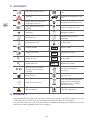
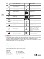
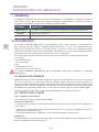
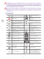
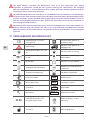
11. GLOSSARY
Consult Instruction for use Suitable for Hospital care
use
Caution! Suitable for Emergency care
use
Keep away from heat and
fl ammable materials. Suitable for Home care use
Keep away from oil and
grease! Fragile, handle with care
Keep dry! Weight of product
Humidity limit Atmospheric pressure
limitation
Temperature limit Use by date
Inlet parameter SN Serial number
Outlet parameter REF Catalogue number
P1Inlet pressure LOT Batch code
P2Outlet pressure REF 1 Reference number
IP 55
Level of security against
foreign parts and water
intrusion
Deliver the battery for
recycling
Manufacturer Do not reuse
Date of manufacture
Take the equipment back for
recycling. Do not dispose
equipment into unsorted
municipal waste.
MR Conditional Type BF applied part
12. WARRANTY
The Standard Warranty period is two years from date of receipt by the GCE Customer (or if this
is not known 2 years from time of the product manufacture shown on the product).
The standard warranty is only valid for products handled according to Instruction for use (IFU)
and general industry good practice and standards.

19/92
EN
APPENDICES:
No. 1 – Technical and performance data
No. 2 – Quick-coupler features and connecting/disconnecting procedure
No. 3 – Post Filling Checks
No. 4 – Valve assembly and fi lling instruction
MANUFACTURER:
GCE, s.r.o. Tel: +420 569 661 111
Zizkova 381 Fax: +420 569 661 602
583 01 Chotebor http://www.gcegroup.com
Czech Republic © GCE, s.r.o.

20/92
CS
1. ÚVOD
Výrobek je ve shodě se základními požadavky směrnice o prostředcích zdravotnické techniky
93/42/EHS a směrnice o přepravitelných tlakových zařízeních 2010/35 EU.
Ventil je navržen dle norem EN ISO 10524-3 a EN ISO 10297.
TERMÍN VÝZNAM
MEDIVITAL®E Kombinovaný ventil MediVital®E vybavený elektronickým indikátorem
tlaku E-GAUGE
E GAUGE E-GAUGE
DISPLEJ Elektronické zobrazovací zařízení.
2. ÚČEL POUŽITÍ
Kombinované ventily MediVital®E jsou určeny pro montáž na tlakové lahve používané pro
medicinální plyny. Tyto kombinované ventily s tlakovou lahví tvoří sestavy, které slouží buď jako
zdroj plynu pro zdravotnická zařízení (anesteziologické přístroje, ventilační přístroje, inkubátory,
atd.) anebo k přímému dávkování plynu do inhalační masky nebo kanyly pacienta.
GCE kombinované ventily jsou určené k použití s následujícími medicinálními plyny:
• kyslík;
• oxid dusný (rajský plyn);
• medicinální vzduch;
• helium;
• oxid uhličitý;
• směsi výše uvedených plynů;
Kombinovaný ventil MediVital®E není určen pro použití s hořlavými anestetiky a látkami
2.1. PACIENTSKÝ PROFIL
Redukční ventil MediVital®E dodává medicinální plyn pomocí průtočné hlavy v rozsahu průtoku
0 do 15 (25) l/min.
Saturace medicinálního plynu musí být stanovena lékařem nebo anesteziologickou zdravotní
sestrou, kteří mají zdravotnické vzdělaní, posoudí zdravotní stav pacienta a podají mu potřebné
množství medicinální plynu.
Zdravotní status – použití v případě, že pacient bude potřebovat dodávku medicinálního plynu
pro podporu dýchání. Rozhodnutí o terapii provádí lékař nebo zdravotnický personál.
Zdravotnický personál – zdravotní sestra, záchranář, zdravotník nebo ošetřovatel, který má
zdravotnické vzdělání.
2.2. UŽIVATELSKÝ PROFIL
Použití v nemocnici nebo v sanitce:
• Vzdělání: personál se zdravotnickým vzděláním
Použití v domácí péči:
Terapie je předepsána lékařem nebo osobami, které mají zdravotnické vzdělání v oblasti pro
podporu dýchání:
• Znalost: proškolení osob se zdravotnickým vzděláním se schopností pročíst, proškolit a
aplikovat znalosti z návodu k použití.
Školení musí být provedeno podle zákonů platných v jednotlivých zemích.
Důležité:
Pacient musí být proškolen lékařem nebo osobou, která má vzdělání v oblasti záchrany života.
ČESKY
NÁVOD K POUŽITÍ: MEDIVITAL®E
La pagina sta caricando ...
La pagina sta caricando ...
La pagina sta caricando ...
La pagina sta caricando ...
La pagina sta caricando ...
La pagina sta caricando ...
La pagina sta caricando ...
La pagina sta caricando ...
La pagina sta caricando ...
La pagina sta caricando ...
La pagina sta caricando ...
La pagina sta caricando ...
La pagina sta caricando ...
La pagina sta caricando ...
La pagina sta caricando ...
La pagina sta caricando ...
La pagina sta caricando ...
La pagina sta caricando ...
La pagina sta caricando ...
La pagina sta caricando ...
La pagina sta caricando ...
La pagina sta caricando ...
La pagina sta caricando ...
La pagina sta caricando ...
La pagina sta caricando ...
La pagina sta caricando ...
La pagina sta caricando ...
La pagina sta caricando ...
La pagina sta caricando ...
La pagina sta caricando ...
La pagina sta caricando ...
La pagina sta caricando ...
La pagina sta caricando ...
La pagina sta caricando ...
La pagina sta caricando ...
La pagina sta caricando ...
La pagina sta caricando ...
La pagina sta caricando ...
La pagina sta caricando ...
La pagina sta caricando ...
La pagina sta caricando ...
La pagina sta caricando ...
La pagina sta caricando ...
La pagina sta caricando ...
La pagina sta caricando ...
La pagina sta caricando ...
La pagina sta caricando ...
La pagina sta caricando ...
La pagina sta caricando ...
La pagina sta caricando ...
La pagina sta caricando ...
La pagina sta caricando ...
La pagina sta caricando ...
La pagina sta caricando ...
La pagina sta caricando ...
La pagina sta caricando ...
La pagina sta caricando ...
La pagina sta caricando ...
La pagina sta caricando ...
La pagina sta caricando ...
La pagina sta caricando ...
La pagina sta caricando ...
La pagina sta caricando ...
La pagina sta caricando ...
La pagina sta caricando ...
La pagina sta caricando ...
La pagina sta caricando ...
La pagina sta caricando ...
La pagina sta caricando ...
La pagina sta caricando ...
La pagina sta caricando ...
La pagina sta caricando ...
-
 1
1
-
 2
2
-
 3
3
-
 4
4
-
 5
5
-
 6
6
-
 7
7
-
 8
8
-
 9
9
-
 10
10
-
 11
11
-
 12
12
-
 13
13
-
 14
14
-
 15
15
-
 16
16
-
 17
17
-
 18
18
-
 19
19
-
 20
20
-
 21
21
-
 22
22
-
 23
23
-
 24
24
-
 25
25
-
 26
26
-
 27
27
-
 28
28
-
 29
29
-
 30
30
-
 31
31
-
 32
32
-
 33
33
-
 34
34
-
 35
35
-
 36
36
-
 37
37
-
 38
38
-
 39
39
-
 40
40
-
 41
41
-
 42
42
-
 43
43
-
 44
44
-
 45
45
-
 46
46
-
 47
47
-
 48
48
-
 49
49
-
 50
50
-
 51
51
-
 52
52
-
 53
53
-
 54
54
-
 55
55
-
 56
56
-
 57
57
-
 58
58
-
 59
59
-
 60
60
-
 61
61
-
 62
62
-
 63
63
-
 64
64
-
 65
65
-
 66
66
-
 67
67
-
 68
68
-
 69
69
-
 70
70
-
 71
71
-
 72
72
-
 73
73
-
 74
74
-
 75
75
-
 76
76
-
 77
77
-
 78
78
-
 79
79
-
 80
80
-
 81
81
-
 82
82
-
 83
83
-
 84
84
-
 85
85
-
 86
86
-
 87
87
-
 88
88
-
 89
89
-
 90
90
-
 91
91
-
 92
92


in altre lingue
- English: GCE MediVital E Operating instructions
- Deutsch: GCE MediVital E Bedienungsanleitung
- slovenčina: GCE MediVital E Návod na používanie
Documenti correlati
-
GCE MEDITEC Istruzioni per l'uso
-
-
-
-
-
-
-
-
-
Altri documenti
-
STIEBEL ELTRON SOL 23 premium Operation Instruction
-
-
-
Chaffoteaux EXPERT CONTROL Assembly And Operation Instructions Manual
-
Edgewater Networks 318CC Owner Assistance Manual
-
-
Foster CTDWC25 Installation, Use And Maintenance Handbook
-
-
Gima 28278 Manuale del proprietario