
Loop Detector
Single and Dual Loops
Plug In
Carlo Gavazzi Industri Over Hadstenvej 40, 8370 Hadsten, Denmark
Instruction manual
Manuel d’instructions
Manuale d’istruzione
Betriebsanleitung
Manual de instrucciones
Brugervejledning
使用手册
LDP1, LDP2

ENGLISH page ....................... 3
DEUTSCH seite .................... 26
FRANÇAIS page ..................50
ESPAÑOL página .................74
ITALIANO pagina .................98
DANSK side ......................122
中文 第页 .........................146

Rev.02 - 12.2021 | LDP1/LDP2 Single and Dual Loop Detector | © 2021 | CARLO GAVAZZI Industri
3
EN
Table of contents
1. Introduction ..............................................................................................................4
1.1 Description ..........................................................................................................................4
1.2 Validity of documentation ......................................................................................................4
1.3 Who should use this documentation ........................................................................................4
1.4 Use of the product ................................................................................................................4
1.5 Safety precautions ................................................................................................................4
1.6 Other documents ..................................................................................................................4
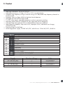
2. Product ..................................................................................................................... 5
2.1 Main features .......................................................................................................................5
2.2 Identification number ............................................................................................................5
2.3 Specifications ......................................................................................................................6
3. Wiring diagrams ....................................................................................................... 7
4. Structure ................................................................................................................... 8
5. LED indications .......................................................................................................... 9
5.1 Power / fault indicator LED ..................................................................................................10
5.2 Loop state LED ....................................................................................................................10
5.3 Relay state LED ................................................................................................................... 10
6. Dip Switch .............................................................................................................. 11
DIP Switch settings for Single Loop (LDP1) .................................................................................... 11
DIP Switch settings for Dual Loop (LDP2) ......................................................................................15
7. Loop installation ..................................................................................................... 18
7.1 Dimension and placement of the loop ...................................................................................18
7.2 Inductance and loop turns.. .................................................................................................19
7.3 Loop wire material .............................................................................................................. 20
7.4 Feeder cable ......................................................................................................................21
7.5 Ground Installation .............................................................................................................22
8. Product Setup Guide ...............................................................................................22
8.1 Channel Selection ..............................................................................................................22
8.2 Sensitivity adjustment ..........................................................................................................23
8.3 Automatic Sensitivity Boost (ASB) .......................................................................................... 24
8.4 Fail Safe and Fail Secure mode ............................................................................................25

Rev.02 - 12.2021 | LDP1/LDP2 Single and Dual Loop Detector | © 2021 | CARLO GAVAZZI Industri
4
EN
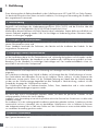
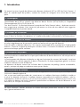
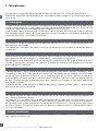
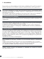
1. Introduction
This manual is a reference guide for Carlo Gavazzi Loop Detector LDP1 and LDP2. It describes the product
specifications as well as how to install, set up and use the product for its intended use.
1.2 Validity of documentation
This manual is valid only for LDP1 and LDP2 Loop Detector and until any newer documentation is published.
This instruction manual describes the functions, operations and installation of the product for its intended
use.
1.6 Other documents
It is possible to find the datasheet, manuals, brochures and electrical drawings on the Internet at
http://gavazziautomation.com
1.5 Safety precautions
This Loop Detector must not be used in applications where personal safety depends on the function of the Loop
Detector.
Installation and use must be carried out by trained technical personnel with basic electrical installation knowledge.
The installer is responsible for correct installation according to local safety regulations and must ensure that a
defective Loop Detector will not result in any hazard to people or equipment. If the Loop Detector is defective, it
must be replaced and secured against unauthorized use.
1.3 Who should use this documentation
This manual contains important information regarding installation and must be read and completely
understood by specialized personnel dealing with these kinds of devices.
We highly recommend that you read the manual carefully before installing the Loop Detector. Please save
the manual for future use. The installation manual is intended solely for qualified technical personnel.
1.4 Use of the product
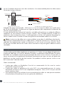
The Loop Detector is primarily used to detect vehicles such as cars, trucks, buses and others.
A loop in the ground is required for the Loop Detector to detect any vehicles above the loop. The device
works on the same principle of an inductive sensor; utilizing the phenomenon of eddy current. When a
metal target/vehicle approaches on top of the loop, the magnetic field generated by the loop interacts with
the target and makes the Loop Detector to change its output.
The Loop Detector can be used at carpark barriers, bollards, gates, toll gantries and many other door
access applications.
1.1 Description
Carlo Gavazzi Loop Detectors are devices designed and manufactured in accordance with IEC international
standards and are subject to the Low Voltage (2014/35/EU) and Electromagnetic Compatibility (2014/30/
EU) EC directives.
All rights to this document are reserved by Carlo Gavazzi Industri: copies may be made for internal use
only. Please do not hesitate informing us to make any suggestions for improving this document.

Rev.02 - 12.2021 | LDP1/LDP2 Single and Dual Loop Detector | © 2021 | CARLO GAVAZZI Industri
5
EN
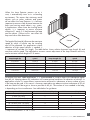
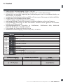
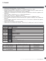
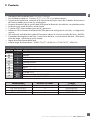
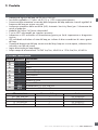
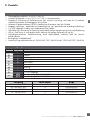
2. Product
2.1 Main features
• Loop input inductance: 20 μH to 1000 μH
• Adjustable sensitivity in 10 steps: 0.01% to 1.00% via potentiometer
• Automatic loop frequency tuning or manual tuning via 4 adjustable loop frequency channels to
avoid crosstalk
• Automatic Sensitivity Boost (ASB) for high bed vehicle detection
• Selectable fail safe and fail secure mode
• 2 x SPDT relay outputs, selectable operation as pulse or presence switching
• Multicolor power/fault LED indication for easy setup and intuitive diagnostic
• Individual loop state multicolor LED to indicate different loop status and fault
• Loop diagnostic capability: loop short circuit, loop open circuit, inductance out of range,
channel crosstalk
• Directional logic for dual loop
• Wide range power supply: 24-240 VAC/VDC, 45-65 Hz or 12-36 VAC/VDC, 45-65 Hz
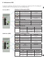
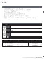
2.2 Identification number
Code Option Description
L-Loop
D-Detector
P-Plug in
x1Number of loops
2Number of loops
P-Potentiometer
A-Adjustment
2-Number of outputs
D-2 x SPDT outputs
xU24 Power supply 24 - 240 VAC/VDC
U12 Power supply 12 - 36 VAC/VDC
Supply Number of loops Code
24 - 240 VAC/VDC 1 LDP1PA2DU24
24 - 240 VAC/VDC 2 LDP2PA2DU24-
12 - 36 VAC/VDC 1 LDP1PA2DU12
12 - 36 VAC/VDC 2 LDP2PA2DU12

Rev.02 - 12.2021 | LDP1/LDP2 Single and Dual Loop Detector | © 2021 | CARLO GAVAZZI Industri
6
EN
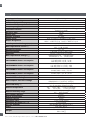
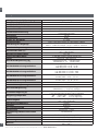
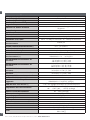
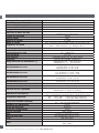
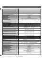
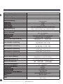
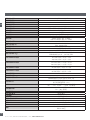
2.3 Specifications
Loop input inductance 20 μH ... 1000 μH
Adjustable sensitivity 0,01% ... 1,00%
Number of adjustable steps 10
Number of frequency channels 4
Frequency range 10 ... 130 kHz
Loop fault detection Short circuit, open circuit, inductance out of range,
frequency crosstalk
Response time 130 ms
Output type Relay
Number of output 2 x SPDT
Output mode Pulse or presence; selectable via dip switch
Output Assignment LDP1: 2 x SPDT for loop 1
LDP2: 1 x SPDT for loop 1 and 1 x SPDT for loop 2
Rated operational voltage (output) 250 VAC/VDC
Rated operational current (Ie)AC1: 5 A @ 250 VAC
DC1: 1 A @ 30 VDC
Mechanical lifetime 15 x 106
Electrical lifetime >100 000 operations (@5A load)
Protection Reverse polarity and overvoltage
Rated operational voltage (UB)LDPxPA2DU24: 24 ... 240 VAC/VDC
LDPxPA2DU12: 12 ... 36 VAC/VDC
LDP1PA2DU24 Power consumption 24 VAC/VDC < 2 W / 2.5 VA
115 VAC/VDC < 2 W / 3 VA
240 VAC/VDC < 2 W / 4 VA
LDP2PA2DU24 Power consumption 24 VAC/VDC < 2.5 W / 3.5 VA
115 VAC/VDC < 2.5 W / 4 VA
240 VAC/VDC < 2.5 W / 5 VA
LDP1PA2DU12 Power consumption 12 VAC/VDC < 2.5 W / 3 VA
36 VAC/VDC < 2 W / 3.5 VA
LDP2PA2DU12 Power consumption 12 VAC/VDC < 3 W / 3.5 VA
36 VAC/VDC < 2.5 W / 4 VA
Rated supply frequency 45 to 65 Hz
Rated insulation voltage 800 V
Rated impulse withstand voltage LDPxPA2DU24: 4 kV (1.2/50 μs)
LDPxPA2DU12: 1 kV/2Ω (1.2/50 μs)
Power-ON delay (tv)5 s for manual frequency tuning
10 s for automatic frequency tuning
Ambient temperature -40° ... +70°C (-40° ... +158°F) (operating)
-40° ... +70°C (-40° ... +158°F) (storage)
Ambient humidity range 0% ... 90% (operating)
0% ... 90% (storage)
Overvoltage category III (IEC)
Degree of protection IP30 (IEC)
Pollution degree 2 (IEC)
Connection type 11 pin circular plug-in
Connection at socket (ZPD11A) Screw terminal
Housing material PPO PX9406-802, PPO Noryl SE1
Colour RAL 7035 (Grey)
Dimensions 81mm (h) x 35.5mm (w) x 60.2mm (d)
Weight LDP1: 105 g
LDP2: 108 g

Rev.02 - 12.2021 | LDP1/LDP2 Single and Dual Loop Detector | © 2021 | CARLO GAVAZZI Industri
7
EN
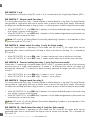
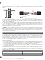
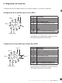
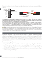
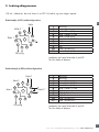
LDP plug in version required to be plugged into a socket ZPD11A which is sold separately.
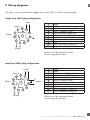
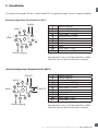
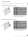
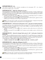
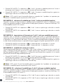
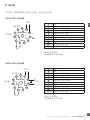
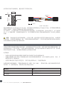
3. Wiring diagrams
Single loop (LDP1) plug configuration
1
2
3
4
567
8
9
10
11
Supply
Loop
Relay
1
Relay 2
1Supply
2Supply
3Relay 1 Normally Open (NO)
4Relay 1 Common (COM)
5Relay 2 Normally Open (NO)
6Relay 2 Common (COM)
7Loop
8Loop
9Earth
10 Relay 2 Normally Closed (NC)
11 Relay 1 Normally Closed (NC)
Earth pin must be connected to earth
Do not wipe grease off pins
Dual loop (LDP2) plug configuration
1
2
3
4
567
8
9
10
11
Supply
Loop 1
Relay
1
Relay 2
Loop 2
1Supply
2Supply
3Relay 1 Normally Open (NO)
4Relay 1 Common (COM)
5Relay 2 Normally Open (NO)
6Relay 2 Common (COM)
7Loop 1
8Loop 1, 2, Earth
9Loop 2
10 Relay 2 Normally Closed (NC)
11 Relay 1 Normally Closed (NC)
Earth pin must be connected to earth
Do not wipe grease off pins

Rev.02 - 12.2021 | LDP1/LDP2 Single and Dual Loop Detector | © 2021 | CARLO GAVAZZI Industri
8
EN
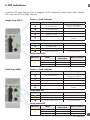
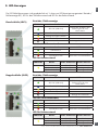
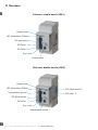
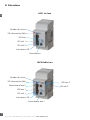
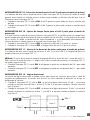
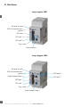
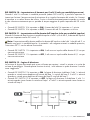
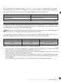
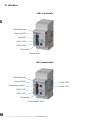
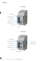
4. Structure
Loop 2 LED
Relay 2 LED
Power / Fault LED
Reset button
Loop LED
Relay 1 LED
Relay 2 LED
Dip switch
Potentiometer
LDP1 Single Loop
Power / Fault LED
Reset button
Potentiometer loop 2
Loop 1 LED
Relay 1 LED
Dip switch
Potentiometer loop 1
LDP2 Dual Loop

Rev.02 - 12.2021 | LDP1/LDP2 Single and Dual Loop Detector | © 2021 | CARLO GAVAZZI Industri
9
EN
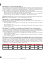
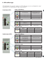
Loop state LED
LED colour LED constant LED Flashing
Inductance OK -
Inductance too high Inductance too low
Loop is open circuit Loop is short circuit
Relay state LED
LED colour Mode Relay
deactivated Relay activated
Presence mode LED OFF LED ON
Pulse mode, 0.1 s LED OFF LED ON for 0.5 s
Pulse mode, 0.5 s LED OFF LED ON for 1.0 s
Power / fault indicator
LED colour LED constant LED Flashing
All OK (ASB OFF) DIP switch changed, but
changes not in effect
All OK (ASB ON) -
Low signal indication -
Channel crosstalk -
-Indication of the frequency
channel
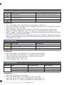
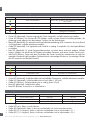
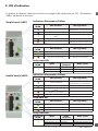
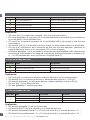
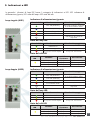
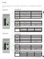
5. LED indications
In general, LDP Loop Detectors have 3 categories of LED indications; namely Power/Fault indicator
LED, Loop state LED and Relay state LED:
Single loop (LDP1)
Loop state LED
LED colour LED constant LED Flashing
Inductance OK -
Inductance too high Inductance too low
Loop is open circuit Loop is short circuit
Relay state LED
LED colour Mode Relay
deactivated Relay activated
Presence mode LED OFF LED ON
Pulse mode, 0.1 s LED OFF LED ON for 0.5 s
Pulse mode, 0.5 s LED OFF LED ON for 1.0 s
Dual loop (LDP2) Power / fault indicator
LED colour LED constant LED Flashing
All OK (ASB OFF) DIP switch changed, but
changes not in effect
All OK (ASB ON) -
Low signal indication -
Channel crosstalk -
-Indication of the frequency
channel

Rev.02 - 12.2021 | LDP1/LDP2 Single and Dual Loop Detector | © 2021 | CARLO GAVAZZI Industri
10
EN
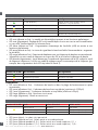
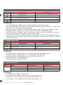
5.1 Power / fault indicator LED
LED colour LED constant LED Flashing
All OK (ASB OFF) DIP switch changed, but changes not in effect
All OK (ASB ON) -
Low signal indication -
Channel crosstalk -
- Indication of the frequency channel
Explanation:
• Green LED (steady): Unit is powered up and everything is working well
• Green LED (flashing): Dip switch has been changed since power up, but change has not taken
effect. Please press the reset button
• Blue LED (steady): Automatic Sensitivity Boost is turned ON and everything is working well
• Yellow LED (steady): Signal level is low in the loop. It is recommended to increase sensitivity
• Red LED (steady): Crosstalk of loop frequency with another loop detected. Select different frequency
channel on DIP switches and reset product
• White LED (flashing): After start up, the number of times the LED flashes, indicates the frequency
channel selected in both manual and automatic frequency tuning mode (e.g. LED flashes two times
is equivalent to channel 2)
5.2 Loop state LED
Explanation:
• Green LED (steady): Loop inductance is within limit and working well
• Yellow LED (steady): Loop inductance is too high (more than 1000µH)
• Yellow LED (flashing): Loop inductance is too low (less than 20µH)
• Red LED (steady): Loop is open circuit
• Red LED (flashing): Loop is short circuit
LED colour LED constant LED Flashing
Inductance OK -
Inductance too high Inductance too low
Loop is open circuit Loop is short circuit
5.3 Relay state LED
Explanation:
• Yellow LED (off): Relay is not activated
• Yellow LED (steady): Relay is activated and in presence mode
• Yellow LED (on for 0.5 s): Relay is activated and in pulse mode, 0.1 s
• Yellow LED (on for 1.0 s): Relay is activated and in pulse mode, 0.5 s
LED colour Mode Relay deactivated Relay activated
Presence mode LED OFF LED ON
Pulse mode, 0.1 s LED OFF LED ON for 0.5 s
Pulse mode, 0.5 s LED OFF LED ON for 1.0 s

Rev.02 - 12.2021 | LDP1/LDP2 Single and Dual Loop Detector | © 2021 | CARLO GAVAZZI Industri
11
ENEN
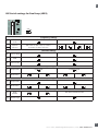
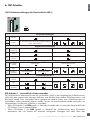
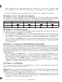
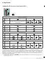
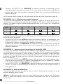
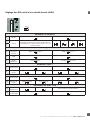
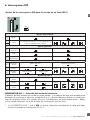
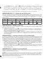
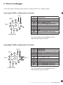
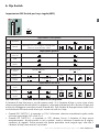
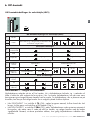
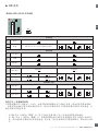
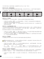
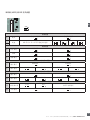
6. Dip Switch
DIP Switch settings for Single Loop (LDP1)
123456789101112
ON
ON
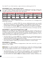
DIP SWITCH 1 - Frequency mode selection
The Loop Detector operates on one out of four channels. If the Loop Detector is located near sources
of electrical or magnetic disturbances, e.g. from other Loop Detectors, some channels can be more
advantageous to use than others. Two Loop Detectors placed in close proximity of each other should
use different channels to avoid crosstalk between the loops.
• When DIP SWITCH 1 is set to ON, the user manually selects which channel is used by setting DIP
switch 2 and 3.
Frequency settings
1Selection
mode Automatic channel selection Manual channel selection
2Channel
selection DIP switch 2 and 3 are not used in
automatic channel selection
1 2 3 4
3
General settings
4 Turn-on delay Delay OFF Delay 2.0 sec
5 ASB ASB OFF ASB ON
6 Failure mode Fail safe Fail secure
Relay 1 settings
7 Output mode Pulse mode Presence mode
8 Time 0.1 sec pulse 0.5 sec pulse Infinite 60 min 10 min 1 min
9 Entry / Exit Vehicle entry Vehicle exit
Relay 2 settings
10 Output mode Pulse mode Presence mode
11 Time 0.1 sec pulse 0.5 sec pulse Infinite 60 min 10 min 1 min
12 Entry / Exit Vehicle entry Vehicle exit

Rev.02 - 12.2021 | LDP1/LDP2 Single and Dual Loop Detector | © 2021 | CARLO GAVAZZI Industri
12
EN
• When DIP SWITCH 1 is set to OFF, during startup the Loop Detector automatically measures
disturbances present on all four channels and selects the channel with best signal conditions.
Note that this procedure will be performed every time the Loop Detector is powered up or reset.
The white LED will show which channel has been selected (refer to the Indication Session on page 10)
DIP SWITCH 2 and 3 - Frequency channel selection
These two DIP switches are used to select which channel the Loop Detector should use. The channels
can only be selected when manual channel selection is set on DIP switch 1. When mode is set to
automatic channel selection, DIP switch 2 and 3 do not have any function.
DIP SWITCH 4 - Turn-on delay
The Loop Detector has a Turn-on delay filter which can be enabled to help to avoid false vehicle
detections.
• When DIP SWITCH 4 is set to ON, the Turn-on delay is activated and any detections shorter than
2 seconds will not cause the output to activate. This function is suitable for detection of stationary
or slow moving vehicles.
• When DIP SWITCH 4 is set to OFF, the Turn-on delay is disabled and output has normal response
time. This function is suitable for detection of fast moving vehicles.
DIP SWITCH 5 - Automatically Sensitivity Boost (ASB)
High bed vehicles such as trucks and trailers normally gives a strong signal when the wheel axles are
inside the circumference of the loop. However the signal drops significantly when the loop is between
the wheel axles or between a truck and its trailer. When ASB function is enabled, the sensitivity is
boosted to avoid output deactivation when signal level is reduced, but high bed vehicle is still on top
of the loop.
• When DIP SWITCH 5 is set to ON, the ASB function is active and sensitivity is boosted to avoid
false deactivations. This mode is recommended for applications where detection of trucks and other
high bed vehicles is needed.
• When DIP SWITCH 5 is set to OFF, the Loop Detector uses normal sensitivity levels. This mode is
recommended for detection of normal cars, vans etc. with low bed height.
DIP SWITCH 6 - Failure mode
This function determines the state of the output relays, both during normal operation and when a failure
is detected in the system.
Note: When Fail Safe mode is selected, the operation of both output relays will be inverted. This
means that the Normally Open (NO) contact will become a Normally Closed (NC) contact and the
Normally Closed (NC) contact will become a Normally Open (NO) contact.
DIP
switch Frequency Channel 1 Frequency Channel 2 Frequency Channel 3 Frequency Channel 4
2OFF ON OFF ON
3OFF OFF ON ON

Rev.02 - 12.2021 | LDP1/LDP2 Single and Dual Loop Detector | © 2021 | CARLO GAVAZZI Industri
13
EN
• When DIP SWITCH 6 is set to ON, the product will operate in FAIL SECURE mode. In case of a
failure on the Loop Detector, in the loop wire or loss of power, the outputs will indicate no detection
of a vehicle.
• When DIP SWITCH 6 is set to OFF, the product will operate in FAIL SAFE mode. In case of a failure
on the Loop Detector, in the loop wire or loss of power, the outputs will indicate detection of a vehicle.
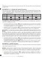
DIP SWITCH 7 - Output mode for relay 1
This setting determines how relay 1 should indicate a vehicle detection in the loop. The Loop Detector
can generate a single pulse, each time a vehicle enters or leaves the loop (Pulse mode). Alternatively
the output can be keept activate as long as there is a vehicle present inside the loop (Presence mode).
• When DIP SWITCH 7 is set to ON relay 1 operates in Presence mode and output is activated as
long as a vehicle is present inside the loop.
• When DIP SWITCH 7 is set to OFF relay 1 operates in Pulse mode and generates a pulse each time
a vehicle enters or leaves the loop.
Note: DIP switch 8 and 9 will have different functionality depending if product is set to operate in
Pulse or Presence mode on DIP switch 7.
DIP SWITCH 8 - Time setting for relay 1 (only for Pulse mode)
When the Loop Detector is operating in Pulse mode (see DIP switch 7), the pulse length can be changed
with DIP switch 8.
• When DIP SWITCH 8 is set to ON relay 1 creates a pulse with a duration of 0.5 s for each
activation.
• When DIP SWITCH 8 is set to OFF relay 1 creates a pulse with a duration of 0.1 s for each
activation.
DIP SWITCH 9 - Entry or Exit mode for relay 1 (only for Pulse mode)
When the Loop Detector is operating in Pulse mode (see DIP switch 7), the output pulse can be
generated either when a vehicle enters the loop or when a vehicle exits the loop. This is selected by
DIP switch 9.
• When DIP SWITCH 9 is set to ON relay 1 creates a pulse each time a vehicle exits the loop.
• When DIP SWITCH 9 is set to OFF relay 1 creates a pulse each time a vehicle enters the loop.
DIP SWITCH 8 & 9 - Timeout setting for relay 1 (only for Presence mode)
When relay 1 is operated in Presence mode (see DIP switch 7), a timeout can be set to limit maximum
activation time of a single vehicle detection. If timeout is set different from infinite, the output will
automatically deactivate, if a vehicle has been constantly detected for longer time than set by DIP
switch 8 and 9.
DIP
switch Infinite 1 hour 10 minutes 1 minute
8OFF ON OFF ON
9OFF OFF ON ON

Rev.02 - 12.2021 | LDP1/LDP2 Single and Dual Loop Detector | © 2021 | CARLO GAVAZZI Industri
14
EN
DIP SWITCH 10 - Output mode for relay 2
This setting determines how relay 2 should indicate a vehicle detection in the loop. The Loop Detector
can generate a single pulse each time a vehicle enters or leaves the loop (Pulse mode). Alternatively
the output can be keept activate as long as there is a vehicle present inside the loop (Presence mode).
• When DIP SWITCH 10 is set to ON relay 2 operates in Presence mode and output is activate as
long as a vehicle is present inside the loop.
• When DIP SWITCH 10 is set to OFF relay 2 operates in Pulse mode and generates a pulse each
time a vehicle enters or leaves the loop.
Note: DIP switch 11 and 12 will have different functionality depending if product is set to operate
in Pulse or Presence mode on DIP switch 10.
DIP SWITCH 11 - Time setting for relay 2 (only for Pulse mode)
When the Loop Detector is operated in Pulse mode (see DIP switch 10), the pulse length can be
changed with DIP switch 11.
• When DIP SWITCH 11 is set to ON relay 2 creates a pulse with a duration of 0.5 s for each
activation.
• When DIP SWITCH 11 is set to OFF relay 2 creates a pulse with a duration of 0.1 s for each
activation.
DIP SWITCH 12 - Entry or Exit mode for relay 2 (only for Pulse mode)
When the Loop Detector is operated in Pulse mode (see DIP switch 10), the output pulse can be
generated either when a vehicle enters the loop or when a vehicle exits the loop. This is selected with
DIP switch 12.
• When DIP SWITCH 12 is set to ON relay 2 creates a pulse each time a vehicle exits the loop.
• When DIP SWITCH 12 is set to OFF relay 2 creates a pulse each time a vehicle enters the loop.
DIP SWITCH 11 & 12 - Timeout setting for relay 2 (only for Presence mode)
When relay 2 is operated in Presence mode (see DIP switch 10), a timeout can be set to limit maximum
activation time of a single vehicle detection. If timeout is set different from infinite, the output will
automatically deactivate, if a vehicle has been constantly detected for longer time than set by DIP
switch 11 and 12.
DIP
switch Infinite 1 hour 10 minutes 1 minute
11 OFF ON OFF ON
12 OFF OFF ON ON

Rev.02 - 12.2021 | LDP1/LDP2 Single and Dual Loop Detector | © 2021 | CARLO GAVAZZI Industri
15
EN
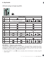
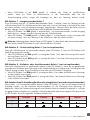
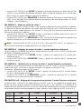
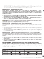
DIP Switch settings for Dual Loop (LDP2)
123456789101112
ON
ON
Frequency settings
1Selection
mode Automatic channel selection Manual channel selection
2Channel
selection DIP switch 2 and 3 are not used in
automatic channel selection
1 2 3 4
3
General settings
4 Turn-on delay Delay OFF Delay 2.0 sec
5 ASB ASB OFF ASB ON
6 Failure mode Fail safe Fail secure
Relay 1 settings
7 Output mode Pulse mode Presence mode
8 Mode select Vehicle entry Vehicle exit Innite 1 m
Relay 2 settings
9 Output mode Pulse mode Presence mode
10 Mode select Vehicle entry Vehicle exit Innite 1 m
Relay 1 & 2 settings
11 Pulse
duration
0.1 s 0.5 s Not used in Presence mode
12 Direction logic OFF ON

Rev.02 - 12.2021 | LDP1/LDP2 Single and Dual Loop Detector | © 2021 | CARLO GAVAZZI Industri
16
EN
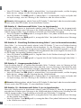
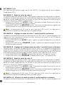
DIP SWITCH 1 to 6
For explanation of functions set by DIP switch 1 to 6, see description for Single Loop Detector (LDP1).
DIP SWITCH 7 - Output mode for relay 1
This setting determines how relay 1 should indicate a vehicle detection in the loop. The Loop Detector
can generate a single pulse each time a vehicle enters or leaves the loop (Pulse mode). Alternatively
the output can be kept activated as long as there is a vehicle present inside the loop (Presence mode).
• When DIP SWITCH 7 is set to ON relay 1 operates in Presence mode and output is activate as long
as a vehicle is present inside the loop.
• When DIP SWITCH 7 is set to OFF relay 1 operates in Pulse mode and generates a pulse each time
a vehicle enters or leaves the loop.
Note: DIP switch 8 will have different functionality depending if product is set to operate in pulse
or presence mode on DIP switch 7.
DIP SWITCH 8 - Mode select for relay 1 (only for Pulse mode)
When the Loop Detector is operating in Pulse mode (see DIP switch 7), the output pulse can be
generated either when a vehicle enters the loop or when a vehicle exits the loop. This is selected by
DIP switch 8.
• When DIP SWITCH 8 is set to ON, relay 1 creates a pulse each time a vehicle exits the loop.
• When DIP SWITCH 8 is set to OFF, relay 1 creates a pulse each time a vehicle enters the loop.
DIP SWITCH 8 - Timeout setting for relay 1 (only for Presence mode)
When relay 1 is operating in Presence mode (see DIP switch 7), a timeout can be set to limit maximum
activation time of a single vehicle detection. If timeout is set different from infinite, the output will
automatically deactivate, if a vehicle has been constantly detected for longer time than set by DIP
switch 8.
• When DIP SWITCH 8 is set to ON relay 1 timeout is set to 1 minute.
• When DIP SWITCH 8 is set to OFF relay 1 timeout is set to infinite.
DIP SWITCH 9 - Output mode for relay 2
This setting determines how relay 2 should indicate a vehicle detection in the loop. The Loop Detector
can generate a single pulse each time a vehicle enters or leaves the loop (Pulse mode). Alternatively
the output can be keept activate as long as there is a vehicle present inside the loop (Presence mode).
• When DIP SWITCH 9 is set to ON relay 2 operates in Presence mode and output is activate as long
as a vehicle is present inside the loop.
• When DIP SWITCH 9 is set to OFF relay 2 operates in Pulse mode and generates a pulse each time
a vehicle enters or leaves the loop.
Note: DIP switch 10 will have different functionality depending if product is set to operate in Pulse
or Presence mode on DIP switch 9.
DIP SWITCH 10 - Mode Select for relay 2 (only for Pulse mode)
When the Loop Detector is operating in Pulse mode (see DIP switch 9), the output pulse can be
generated either when a vehicle enters the loop or when a vehicle exits the loop. This is selected with
DIP switch 10.

Rev.02 - 12.2021 | LDP1/LDP2 Single and Dual Loop Detector | © 2021 | CARLO GAVAZZI Industri
17
EN
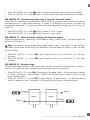
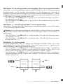
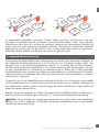
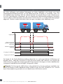
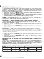
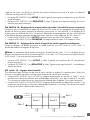
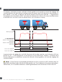
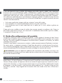
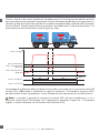
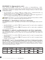
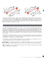
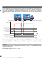
Loop 1 Loop 2
Relay 2
Relay 1
Direction
Direction
• When DIP SWITCH 10 is set to ON relay 2 creates a pulse each time a vehicle exits the loop.
• When DIP SWITCH 10 is set to OFF relay 2 creates a pulse each time a vehicle enters the loop.
DIP SWITCH 10 - Timeout setting for relay 2 (only for Presence mode)
When relay 2 is operating in Presence mode (see DIP switch 9), a timeout can be set to limit maximum
activation time of a single vehicle detection. If timeout is set different from infinite, the output will
automatically deactivate, if a vehicle has been constantly detected for longer time than set by DIP
switch 10.
• When DIP SWITCH 10 is set to ON relay 2 timeout is set to 1 minute.
• When DIP SWITCH 10 is set to OFF relay 2 timeout is set to infinite.
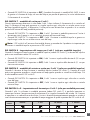
DIP SWITCH 11 - Pulse Duration setting (only for Pulse mode)
When the Loop Detector is operating in Pulse mode on relay 1 and/or relay 2, the pulse length can
be set with DIP switch 11.
Note: The duration setting changes pulse length of both relay 1 and relay 2, if they are both
operated in pulse mode. If both relays are operated in Presence mode, DIP switch 11 does not have
any functionality.
• When DIP SWITCH 11 is set to ON, relay creates a pulse with a duration of 0.5 s for each
activation.
• When DIP SWITCH 11 is set to OFF, relay creates a pulse with a duration of 0.1 s for each
activation.
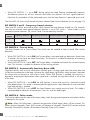
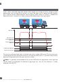
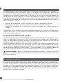
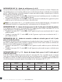
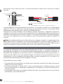
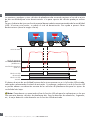
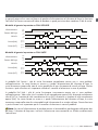
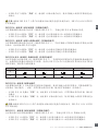
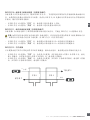
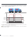
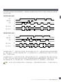
DIP SWITCH 12 - Direction logic
The directional logic function can be used to count vehicles in and out of a parking area. When this
function is activated, the relays indicate which direction the vehicle was traveling.
• When DIP SWITCH 12 is set to ON, Direction logic is enabled. Relay 1 will activate when a vehicle
first drives inside loop 1 and then loop 2. Relay 2 will activate when a vehicle first drives inside
loop 2 and then loop 1.
• When DIP SWITCH 12 is set to OFF, Direction logic is disabled. Relay 1 will activate when a
vehicle is detected in loop 1 and relay 2 will activate when a vehicle is detected in loop 2.

Rev.02 - 12.2021 | LDP1/LDP2 Single and Dual Loop Detector | © 2021 | CARLO GAVAZZI Industri
18
EN
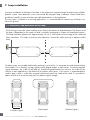
30 cm
1 foot
45º
45º
45º
45º
b
a
30 cm
1 foot
30 cm
1 foot
45º
45º
45º
45º
b
a
30 cm
1 foot
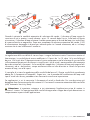
Road curb
Road curb
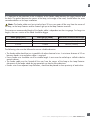
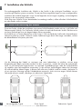
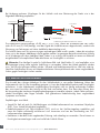
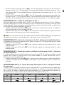
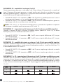
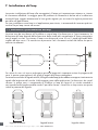
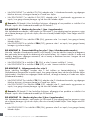
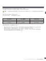
7. Loop installation
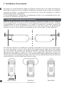
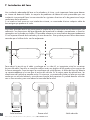
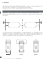
7.1. Dimension and placement of the loop
A proper installation of the loop in the road, is the single most important factor for achieving a reliable
detector system. Most detection issues are caused by improper loop installation. Please read these
guidelines carefully to ensure the best possible performance in the application.
If a new loop is installed in an existing application, it is recommended to remove any old loop wire
left in the ground.
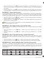
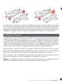
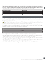
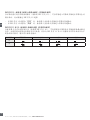
The first thing to consider when installing a new loop is the dimension and placement. The dimension of
the loop is dependent on the road size and is normally rectangular in shape with chamfered corners.
The loop should be placed with approximately 30 cm (1 foot) distance to the edge of the road and
other road lanes. This helps to prevent false detections caused by traffic passing in adjacent traffic
lanes.
To reduce stress on the cable and thereby prolong its service life, it is important to avoid sharp bending
of the cable. This is done by cutting a groove at 45 degree angles in each corner. To achieve optimal
signal conditions, the width of the loop (a) should be approximately the same as the width of the
vehicle. In most applications, the dimension of vehicles often varies, in this case it is recommended to
install a loop, which is wider than a typical vehicle and match the width of the road. It is possible to
detect vehicles with a narrow loop, but this reduces signal strength.
Excellent signal Good signal Reduced signal
Track width

Rev.02 - 12.2021 | LDP1/LDP2 Single and Dual Loop Detector | © 2021 | CARLO GAVAZZI Industri
19
EN
Minimum
Loop Length (b) Maximum vehicle
speed Minimum
Loop Length (b) Maximum vehicle
speed
0.25 meter 75 km/h 0.8 feet 47 mph
0.50 meter 80 km/h 1.6 feet 50 mph
1.00 meter 95 km/h 3.3 feet 59 mph
2.00 meter 120 km/h 6.6 feet 75 mph
5.00 meter 200 km/h 16.4 feet 124 mph
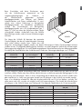
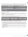
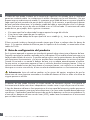
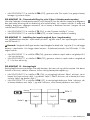
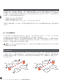
When the Loop Detector powers up or is
reset, it automatically tunes to its surrounding
environment. This means that stationary metal
objects such as poles, cabinets and grates
do not affect the Loop Detector. It is however
important to ensure a safe distance between the
loops and moving metal objects, e.g., gates.
In applications where there are moving metal
objects, it is important to ensure minimum
distance of 1 meter (3.3 feet) between the loop
and the object. Otherwise this can affect the
loop and cause false detections.
The length of the loop (b) influences the maximum
speed at which a vehicle can be traveling
and still be detected. For applications where
detection of high speed vehicles is needed, it
is important to consider this length. The table below shows relation between loop length (b) and
maximum vehicle speed. The table below assumes correct adjustment of the Loop Detector sensitivity
and a minimum vehicle length of 2.5 meters.
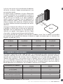
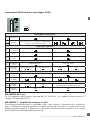
7.2. Inductance and loop turns
To achieve the most stable application, it is recommended to install a loop with inductance higher
than 80 µH. Keeping above this inductance will create optimal conditions for detection of vehicles. In
applications where it is impossible or inconvenient to achieve this inductance, a lower number of turns
in the loop can be used. In this case it is however required to stay above minimum inductance of 20 µH
and aim should still be to get as close as possible to 80 µH. The number of turns needed in the loop,
is depending on the circumference. See table below for guidance.
Loop circumference 1) Recommended turns (80 µH) Minimum turns (20 µH)
2 meter (6.6 feet) 13 9
5 meter (16.4 feet) 7 5
6 - 7 meter (19.7 - 23 feet) 6 4
8 - 9 meter (26.2 - 29.5 feet) 5 3
10 - 14 meter (32.8 - 45.9 feet) 4 3
15 - 23 meter (49.2 - 75.5 feet) 3 2
24 - 30 meter (78.7 - 98.4 feet) 2 1
1) Loop circumference = 2 x a + 2 x b.
Loop
min. 1 m
3.3 feet

Rev.02 - 12.2021 | LDP1/LDP2 Single and Dual Loop Detector | © 2021 | CARLO GAVAZZI Industri
20
EN
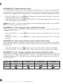
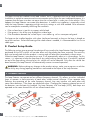
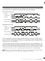
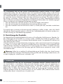
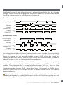
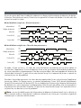
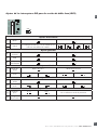
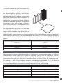
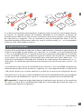
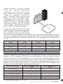
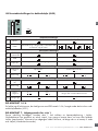
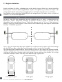
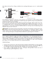
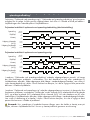
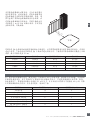
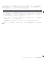
When installing multiple turns in the loop, it is recommended to place the wires like shown in figure
below.
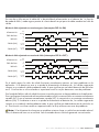
The recommended groove depth is 30-50 mm (1.2-2.0 inches). If the wires are installed deeper than
50 mm (2.0 inches), the detection signal for the Loop Detector is reduced and detection of high bed
vehicles can be compromised.
It is possible to create the loop using a single multi-conductor cable by soldering the individual conductors
in series like shown in figure above. In the example shown, the 4-conductor cable creates a loop with
4 turns. If this approach is used, it is important to protect the soldered joints against any moisture with
adhesive-lined heat shrink tubing or equivalent.
Note: A common problem for loop failures is wire splicing. It is recommended to use one continuous
wire without any splices. If wire splicing is used, the wires must be soldered. Screw or spring terminals
are not allowed in the ground. All wire splices must be insulated against moisture with adhesive-lined
heat shrink tubing or equivalent.
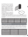
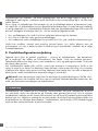
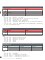
7.3. Loop wire material
It is important to select the right type of cable for the loop wire. If the insulating material is not suitable
for the application, the cable jacket can crack or absorb moisture. It is a common problem to have
moisture penetration in the cable jacket, which can cause a wire shorting to ground. This can lead to
conditions where the application works well while it is dry, but starts failing in high humidity conditions
or rain. A cracked cable insulation can lead to similar issues.
Cable recommendations:
• Wire insulating material of cross-linked polyethylene is recommended for both cold and hot sealant.
• Wire insulating material of polyvinyl chloride (PVC) is only recommended for hot sealant and if the
wires are encapsulating completely. Otherwise, PVC insulating material is not advised.
• It is important to avoid any voids in the sealing around the cable. This can allow moisture to build
up and cause loop failures.
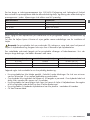
To troubleshoot broken wires an insulation tester (500 MΩ minimum) can be used. Place one wire from
the meter to the disconnected wire loop and place the other meter wire in the ground. Testing should
be performed with AC voltage.
Measured resistance Conclusion
100 to 1000 MΩ Loop condition is good
50 to 100 MΩ Loop integrity is questionable
0 to 50 MΩ Loop needs to be replaced
4-5 mm
30-50 mm
Loop wire
Loop sealant
Road surface
1.2-2 inches
= Solder joints
Loop wire 1
Loop wire 2
Soldering of a single multi-conductor cableLoop with multiple turns
La pagina si sta caricando...
La pagina si sta caricando...
La pagina si sta caricando...
La pagina si sta caricando...
La pagina si sta caricando...
La pagina si sta caricando...
La pagina si sta caricando...
La pagina si sta caricando...
La pagina si sta caricando...
La pagina si sta caricando...
La pagina si sta caricando...
La pagina si sta caricando...
La pagina si sta caricando...
La pagina si sta caricando...
La pagina si sta caricando...
La pagina si sta caricando...
La pagina si sta caricando...
La pagina si sta caricando...
La pagina si sta caricando...
La pagina si sta caricando...
La pagina si sta caricando...
La pagina si sta caricando...
La pagina si sta caricando...
La pagina si sta caricando...
La pagina si sta caricando...
La pagina si sta caricando...
La pagina si sta caricando...
La pagina si sta caricando...
La pagina si sta caricando...
La pagina si sta caricando...
La pagina si sta caricando...
La pagina si sta caricando...
La pagina si sta caricando...
La pagina si sta caricando...
La pagina si sta caricando...
La pagina si sta caricando...
La pagina si sta caricando...
La pagina si sta caricando...
La pagina si sta caricando...
La pagina si sta caricando...
La pagina si sta caricando...
La pagina si sta caricando...
La pagina si sta caricando...
La pagina si sta caricando...
La pagina si sta caricando...
La pagina si sta caricando...
La pagina si sta caricando...
La pagina si sta caricando...
La pagina si sta caricando...
La pagina si sta caricando...
La pagina si sta caricando...
La pagina si sta caricando...
La pagina si sta caricando...
La pagina si sta caricando...
La pagina si sta caricando...
La pagina si sta caricando...
La pagina si sta caricando...
La pagina si sta caricando...
La pagina si sta caricando...
La pagina si sta caricando...
La pagina si sta caricando...
La pagina si sta caricando...
La pagina si sta caricando...
La pagina si sta caricando...
La pagina si sta caricando...
La pagina si sta caricando...
La pagina si sta caricando...
La pagina si sta caricando...
La pagina si sta caricando...
La pagina si sta caricando...
La pagina si sta caricando...
La pagina si sta caricando...
La pagina si sta caricando...
La pagina si sta caricando...
La pagina si sta caricando...
La pagina si sta caricando...
La pagina si sta caricando...
La pagina si sta caricando...
La pagina si sta caricando...
La pagina si sta caricando...
La pagina si sta caricando...
La pagina si sta caricando...
La pagina si sta caricando...
La pagina si sta caricando...
La pagina si sta caricando...
La pagina si sta caricando...
La pagina si sta caricando...
La pagina si sta caricando...
La pagina si sta caricando...
La pagina si sta caricando...
La pagina si sta caricando...
La pagina si sta caricando...
La pagina si sta caricando...
La pagina si sta caricando...
La pagina si sta caricando...
La pagina si sta caricando...
La pagina si sta caricando...
La pagina si sta caricando...
La pagina si sta caricando...
La pagina si sta caricando...
La pagina si sta caricando...
La pagina si sta caricando...
La pagina si sta caricando...
La pagina si sta caricando...
La pagina si sta caricando...
La pagina si sta caricando...
La pagina si sta caricando...
La pagina si sta caricando...
La pagina si sta caricando...
La pagina si sta caricando...
La pagina si sta caricando...
La pagina si sta caricando...
La pagina si sta caricando...
La pagina si sta caricando...
La pagina si sta caricando...
La pagina si sta caricando...
La pagina si sta caricando...
La pagina si sta caricando...
La pagina si sta caricando...
La pagina si sta caricando...
La pagina si sta caricando...
La pagina si sta caricando...
La pagina si sta caricando...
La pagina si sta caricando...
La pagina si sta caricando...
La pagina si sta caricando...
La pagina si sta caricando...
La pagina si sta caricando...
La pagina si sta caricando...
La pagina si sta caricando...
La pagina si sta caricando...
La pagina si sta caricando...
La pagina si sta caricando...
La pagina si sta caricando...
La pagina si sta caricando...
La pagina si sta caricando...
La pagina si sta caricando...
La pagina si sta caricando...
La pagina si sta caricando...
La pagina si sta caricando...
La pagina si sta caricando...
La pagina si sta caricando...
La pagina si sta caricando...
La pagina si sta caricando...
La pagina si sta caricando...
La pagina si sta caricando...
La pagina si sta caricando...
La pagina si sta caricando...
La pagina si sta caricando...
La pagina si sta caricando...
-
 1
1
-
 2
2
-
 3
3
-
 4
4
-
 5
5
-
 6
6
-
 7
7
-
 8
8
-
 9
9
-
 10
10
-
 11
11
-
 12
12
-
 13
13
-
 14
14
-
 15
15
-
 16
16
-
 17
17
-
 18
18
-
 19
19
-
 20
20
-
 21
21
-
 22
22
-
 23
23
-
 24
24
-
 25
25
-
 26
26
-
 27
27
-
 28
28
-
 29
29
-
 30
30
-
 31
31
-
 32
32
-
 33
33
-
 34
34
-
 35
35
-
 36
36
-
 37
37
-
 38
38
-
 39
39
-
 40
40
-
 41
41
-
 42
42
-
 43
43
-
 44
44
-
 45
45
-
 46
46
-
 47
47
-
 48
48
-
 49
49
-
 50
50
-
 51
51
-
 52
52
-
 53
53
-
 54
54
-
 55
55
-
 56
56
-
 57
57
-
 58
58
-
 59
59
-
 60
60
-
 61
61
-
 62
62
-
 63
63
-
 64
64
-
 65
65
-
 66
66
-
 67
67
-
 68
68
-
 69
69
-
 70
70
-
 71
71
-
 72
72
-
 73
73
-
 74
74
-
 75
75
-
 76
76
-
 77
77
-
 78
78
-
 79
79
-
 80
80
-
 81
81
-
 82
82
-
 83
83
-
 84
84
-
 85
85
-
 86
86
-
 87
87
-
 88
88
-
 89
89
-
 90
90
-
 91
91
-
 92
92
-
 93
93
-
 94
94
-
 95
95
-
 96
96
-
 97
97
-
 98
98
-
 99
99
-
 100
100
-
 101
101
-
 102
102
-
 103
103
-
 104
104
-
 105
105
-
 106
106
-
 107
107
-
 108
108
-
 109
109
-
 110
110
-
 111
111
-
 112
112
-
 113
113
-
 114
114
-
 115
115
-
 116
116
-
 117
117
-
 118
118
-
 119
119
-
 120
120
-
 121
121
-
 122
122
-
 123
123
-
 124
124
-
 125
125
-
 126
126
-
 127
127
-
 128
128
-
 129
129
-
 130
130
-
 131
131
-
 132
132
-
 133
133
-
 134
134
-
 135
135
-
 136
136
-
 137
137
-
 138
138
-
 139
139
-
 140
140
-
 141
141
-
 142
142
-
 143
143
-
 144
144
-
 145
145
-
 146
146
-
 147
147
-
 148
148
-
 149
149
-
 150
150
-
 151
151
-
 152
152
-
 153
153
-
 154
154
-
 155
155
-
 156
156
-
 157
157
-
 158
158
-
 159
159
-
 160
160
-
 161
161
-
 162
162
-
 163
163
-
 164
164
-
 165
165
-
 166
166
-
 167
167
-
 168
168
-
 169
169
-
 170
170


CARLO GAVAZZI LDP2PA2DU24 Manuale del proprietario
- Tipo
- Manuale del proprietario
- Questo manuale è adatto anche per
in altre lingue
Documenti correlati
Altri documenti
-
Genius RMG1 RMG2 Istruzioni per l'uso
-
-
PRASTEL MLX24V Manuale utente
-
Crowcon Hydra256 Istruzioni per l'uso
-
ADEMCO Security System VISTA-15CN Installation And Setup Manual
-
-
General Monitors TA402A Single Channel Trip Amplifier Manuale del proprietario
-
-
CAME PS ONE Guida d'installazione
-
Risco WatchOUT XTreme 315DT Installation Instructions Manual