ProLights SMARTMODULA Manuale utente
- Categoria
- Proiettori
- Tipo
- Manuale utente

EN - IT
USER MANUAL
MANUALE UTENTE
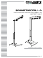
NEW FORM OF DECOR AND MODULAR
BATTERY LIGHT
SMARTMODULA

All rights reserved by Music & Lights S.r.l. No part of this instruction manual may be
reproduced in any form or by any means for any commercial use.
In order to improve the quality of products, Music&Lights S.r.l. reserves the right to modify the
characteristics stated in this instruction manual at any time and without prior notice.
All revisions and updates are available in the ‘manuals’ section on site www.musiclights.it
REV.03-10/18

Packing content
• SMARTMODULA
• Power cable
• User manual
TABLE OF
CONTENTS
Safety
General instructions
Warnings and installation precautions
1 Introduction
1. 1 Description
1. 2 Technical specications
1. 3 Technical specications MODULASPOTFC-DY
1. 4 Technical specications MODULAWASHFC-D
1. 5 Battery features
1. 6 Operating elements and connections
2 Installation
2. 1 Mounting
3 Functions and settings
3. 1 Operation
3. 2 Basic
3. 3 Menu structure
3. 4 DMX Mode
3. 5 DMX conguration
3. 6 DMX Addressing
3. 7 Pixel mode
3.8 Wireless
3. 9 Backlight
3. 10Flip display
3. 11 Dimmer
3. 12 Calibration
3. 13 Reload Default
3. 14 Time info
3. 15 Software version
3. 16 Static mode
3. 17 Controller IR
3. 18 DMX control
4 Maintenance
4. 1 Maintenance and cleaning the unit
4. 2 Fuse replacement
4. 3 Troubleshooting
2
2
3
3
6
6
7
8
9
11
11
12
13
13
13
13
13
14
14
14
14
14
15
15
15
15
16
18
18
18

SMARTMODULA
2
WARNING! Before carrying out any operations with the unit, carefully read this instruction
manual and keep it with cure for future reference. It contains important information about
the installation, usage and maintenance of the unit.
SAFETY
General instruction
• The products referred to in this manual conform to the European Community Directives and are there-
fore marked with .
• The unit is supplied with hazardous network voltage (230V~). Leave servicing to skilled personnel only.
Never make any modications on the unit not described in this instruction manual, otherwise you will
risk an electric shock.
• Connection must be made to a power supply system tted with ecient earthing (Class I appliance ac-
cording to standard EN 60598-1). It is, moreover, recommended to protect the supply lines of the units
from indirect contact and/or shorting to earth by using appropriately sized residual current devices.
• The connection to the main network of electric distribution must be carried out by a qualied electrical
installer. Check that the main frequency and voltage correspond to those for which the unit is designed
as given on the electrical data label.
• This unit is not for home use, only professional applications.
• Never use the xture under the following conditions:
- in places subject to vibrations or bumps;
- in places with a temperature of over 45 °C.
• Make certain that no inammable liquids, water or metal objects enter the xture.
• Do not dismantle or modify the xture.
• All work must always be carried out by qualied technical personnel. Contact the nearest sales point for
an inspection or contact the manufacturer directly.
• If the unit is to be put out of operation denitively, take it to a local recycling
plant for a disposal which is not harmful to the environment.
Warnings and installation precautions
• If this device will be operated in any way dierent to the one described in this manual, it may suer
damage and the guarantee becomes void. Furthermore, any other operation may lead to dangers like
short circuit, burns, electric shock, etc.
• Before starting any maintenance work or cleaning the projector, cut o power from the main supply.
• Always additionally secure the projector with the safety rope. When carrying out any work, always com-
ply scrupulously with all the regulations (particularly regarding safety) currently in force in the country
in which the xture’s being used.
• Install the xture in a well ventilated place.
• Keep any inammable material at a safe distance from the xture.
• Shields, lenses or ultraviolet screens shall be changed if they have become damaged to such an extent
that their eectiveness is impaired.
• The lamp (LED) shall be changed if it has become damaged or thermally deformed.
• Never look directly at the light beam. Please note that fast changes in lighting, e. g. ashing light, may
trigger epileptic seizures in photosensitive persons or persons with epilepsy.
• Do not touch the product’s housing when operating because it may be very hot.

3
SMARTMODULA
- 1 - INTRODUCTION
1.1 DESCRIPTION
SMARTMODULA is a cable-free battery xture which establishes a new form of decor lighting for events,
banquets and gardens. Its modular and customizable assembly allow to use the luminaire standing from
the oor or hanged as a pinspot four-bar, and packed in a comfortable carry-on sizes. Thelight emitters
are adjustable and can slide on the track for a perfect focusing, and as well be replaced from Spot to Wash
or mixed congurations and available in FC or White color mixing.
SMARTMODULA (Core components to be completed with accessories) includes:
- Floor metal base plate
- Base with supporting bar
- Extension bar with adjustable wight
- Heading bar with light track and electronics (containing 1 battery)
OPTIONALaccessories to complete the Core element:
- MODULASPOT: 2pcs Spot LED Dot with 1 LED source 12° beam, available in FC or WHite color mixing
(Max 6pcs on each SMARTMODULA).
- MODULAWASH: 1pc wash LED strip with 12x3W LED, 60° beam, available in FC or WHite color mixing
(Max 1pcs on each SMartModula + 2 Spot).
- MODULABBAT: 1pc base extra-battery to be installed inside the Base to extend battery operation (Max
2pcs MODULABBAT in each baseplate).
Features:
MODULA design allows oor standing with exible swivel joints and tiltable stand, or hanging with quick-
lock omega brackets
Accessory xtures available in RGBW/FC and White Color mixing, as well as with Spot or Wash Optics, each
emitter is pixel mapped, can slides and be focused individually (not included)
The base houses room for extra battery (optional) and the stand can be adjusted in height.
1.2 TECHNICAL SPECIFICATIONS
LIGHT SOURCE
• Source: W Light source is supplied as accessory as SPOT or WASH, FC or White
• CT: Optional - FC or WH SPOT 5600 K or WH WASK 6400 K
• Source Life Expectancy: >30.000 h
• Other: Light source is supplied as accessory as SPOT or WASH, FC or White
OPTICS
• Beam Angle: SPOT (Opt) 15°; WASH (Opt) 60 °
COLOR SYSTEM
• Color Mixing: Interchangeable light source: SPOTs or WASH with FullColor or White LED source
DYNAMIC EFFECTS
• Static Color Mode: Selection of static color
• Manual Color Mode: Manual adjustment of color
• Auto Mode: Built-in programs with execution speed adjustment

SMARTMODULA
4
BODY
• Hardware On-board: See the Introduction description
• Pan Angle: 360 ° Metal joint for 360° rotation of header bar
• Tilt Angle:120 ° Manual
• Body: Sturdy stretching aluminium body conceived for long-time durability
• Body Color: Matte black
CONTROL
• Protocols: WDMX
• Pixel Control: Pixel2Pixel control
• W-DMX: Included, Wireless Solution receiver
• Display: Black OLED high resolution display
• IR: Infra-Red sensor controlled by remote
ELECTRONICS
• Dimmer: Linear 0~100% electronic dimmer
• Strobe/Shutter:1~25 Hz, electronic
• Operating Temperature: -10° ~ +40°
• Flicker: Flicker free operation
ELECTRICAL
• Power Supply: 100-240V – 50/60Hz
BATTERY
• Battery:(Head) 1x14.8 V - (Base - optional) 1x14.8 V Lithium
• Autonomy in color change mode, up to:refer to user manual for max h
• Autonomy in single color mode, up to:refer to user manual for max h
• Autonomy in full-on, up to:refer to user manual for max h
• Recharge Connection: Power cable
• Recharge Time:Head battery 5,5 h/max Base battery 11 h/max
• Battery Status: LED battery status indicator
• Other:Check User manual for further information about battery autonomy for all possible compositions
PHYSICAL
• Cooling: Natural cooling of the peculiar chassis and to absence of fans
• Suspension And Fixing: Hanging bracket suitable for safe hanging and positioning
• Power Connection: PowerCON TRUE1 in
• IP:20
• Dimensions (WxHxD): 735x(1456~1916)x958 mm
• Weight:w/o baseplate 23,5Kg, with baseplate 38,5 kg

5
SMARTMODULA
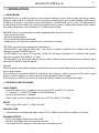
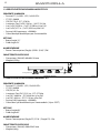
Technical drawing Fig.1
1916 [75.43 in]
1456 [57.32 in]
689 [27.14 in]
735 [28.93 in]

SMARTMODULA
6
80 [3.14 in]
110 [4.33 in]
80 [3.14 in]
1.4 TECHNICAL SPECIFICATIONS MODULAWASHFC-DY
LIGHT SOURCE
• Source:(FC) 12x6 W - (DY) 12x3 W LEDs
• CT:(DY) 6400 K
• CRI:(DY) 81 Ra
• Luminous Flux:(DY) 1213 lm - (FC) 2778 lm
• Lux:(DY) 3800 lux - (FC) 8340 lux @1m Full
• Lux:(DY) 468 lux - (FC) 1110 lux @3m Full
• Source Life Expectancy: >50.000 h
• Other:Max 1pc Modulawash per Smartmodula (+2pcs SPOT)
OPTICS
• Beam Angle:60 °
• Field Angle:65 °
ELECTRICAL
• Power Consumption:(Single FC) 27 W - (Single DY) 15W
PHYSICAL
• Dimensions (WxHxD):500x55x55 mm
• Weight:0,8 kg
1.3 TECHNICAL SPECIFICATIONS MODULASPOTFC-DY
LIGHT SOURCE
• Source:(FC) 1x10 W - (DY) 1x3 W LEDs
• CT:(DY) 5600 K
• CRI:(DY) 70,9 - (FC) 37.6 Ra
• Luminous Flux:(1xDY) 194 lm - (1xFC) 254 lm
• Lux:(1xDY) 5320 lx - (1xFC) 5150 lux @1m Full
• Lux:(1xDY) 477 lx - (1xFC) 453 lux @3m Full
• Source Life Expectancy: >50.000 h
• Other:Max 6pc Modulaspot per Smartmodula
OPTICS
• Beam Angle:15 °
• Field Angle:23 °
ELECTRICAL
• Power Consumption:(Single FC) 5.5 W - (Full FC) 33 W - (Single DY) 1.5 W - (Full DY) 9 W
PHYSICAL
• Dimensions (WxHxD):80x80x110 mm
• Weight:0,25 kg
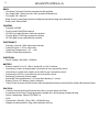
Technical drawing Fig.2

7
SMARTMODULA
55 [2.16 in]
55 [2.16 in]
500 [19.68 in]
Technical drawing Fig.3
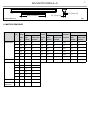
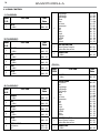
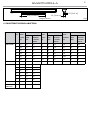
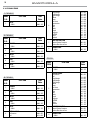
1.5 BATTERY FEATURES
QTY
(PCS)
FULL
COLOR’S
POWER
(W)
LIGHTING HOURS (h) SINGLE
COLOR’S
POWER
(W)
LIGHTING HOURS (h) COLOR
CHANGING’S
POWER (W)
LIGHTING HOURS (h)
HEAD
BAR’S
BATTERY
HEAD BAR’S
BATTERY+BACK
UP BATTERY
HEAD
BAR’S
BATTERY
HEAD BAR’S
BATTERY+BACK
UP BATTERY
HEAD
BAR’S
BATTERY
HEAD BAR’S
BATTERY+BACK
UP BATTERY
MODULASPOTFC 1 5,8 25 75 1,9 77 231 2,85 51 154
2 11,4 13 39 3,8 38 115 5,7 25 76
3 17,1 9 26 5,7 25 76 8,55 17 51
4 22,8 6 19 7,6 19 58 11,4 13 39
5 27,7 5 16 9,5 15 46 14,25 10 31
6 34,1 4 13 11,4 13 38 17,1 8 25
MODULAWASHFC 1 52 2 8 21,3 6 21 31,95 4 13
MODULASPOTDY 1 1,5 97 292
2 3 49 146
3 4,5 32 97
4 6 24 73
5 7,5 19 57
6 9 16 49
MODULAWASHDY 1 15 9 27
MODULAWASH
MODULASPOT
1
2
54 2 8

SMARTMODULA
8
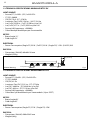
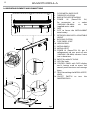
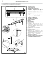
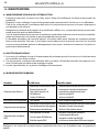
1.6 OPERATING ELEMENTS AND CONNECTIONS
Fig.4
1. FLOOR METAL BASE PLATE
2. THREADED HOLES M8
3. BASE WITH SUPPORTING BAR
4. POWER IN (PowerCON IN):
for connection to a socket
(100-240V~/50-60Hz) via the
supplied mains cable.
5. FUSE
6. SLOT to house the MODULABBAT
extra battery
7. EXTENSION BAR WITH ADJUSTABLE
HEIGHT
8. BLOCKING SYSTEM
9. FLEX SWIVEL JOINT
10. HEADING BAR
11. MODULAWASH
12. MODULASPOT
13. POWER IN (PowerCON IN): per il
collegamento ad una presa di rete
(100-240V~/50-60Hz) tramite il cavo
rete in dotazione.
14. IMPUT for cable DC IN 24V.
15. HOLE for hook.
16. CONTROL PANEL with OLED display
and 4 button used to access the
control panel functions and manage
them.
17. TRACK to working the MODULASPOT/
WASH.
18. ON/OFF SWITCH to turn the
SMARTMODULA.
1
3
5
4
6
7
2
8
9
10
12
11
16
514
13
15
17
18

9
SMARTMODULA
3
1
7
8
9
1
2
3 4
- 2 - INSTALLATION
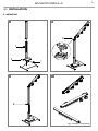
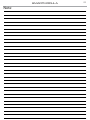
2.1 MOUNTING
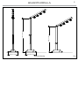
Fig.5 - Examples conguration

SMARTMODULA
10
165°
958 [37.71 in]
165°
958 [37.71 in]
165°
958 [37.71 in]
165°
958 [37.71 in]
1916 [75.43 in]
735 [28.94 in]
2866 [112.84 in]
1456 [57.33 in]
735 [28.94 in]
2406 [94.74 in]
1916 [75.43 in]
735 [28.94 in]
2868 [112.91 in]
1456 [57.33 in]
735 [28.94 in]
2408 [94.80 in]
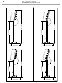
Fig.6

11
SMARTMODULA
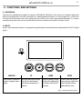
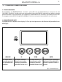
Fig.7 - Functions of the buttons
- 3 - FUNCTIONS AND SETTINGS
3.1 OPERATION
Connect the supplied main cable to a socket (100-240 VAC-50/60 Hz). Then the unit is ready for operation
and can be operated via a DMX controller or it independently performs its show program in succession.
To switch o, disconnect the mains plug from the socket. For a more convenient operation it is recom-
mended to connect the unit to a socket which can be switched on and o via a light switch.
3.2 BASIC
Access control panel functions using the four panel buttons located directly underneath the OLED Display
(g.4).
MENU/ESC UP DOWN ENTER
Used to access the menu or
to return a previous menu
option
Navigates downwards through
the menu list and increases
the numeric value when in a
function
Navigates upwards through
the menu list and decreases
the numeric value when in
a function
Used to select and store the
current menu or conrm the
current function value or
option within a menu

SMARTMODULA
12
3.3 MENU STRUCTURE
MENU
1 CONNECT
ð
DMX Address
ð
Value (001-485)
DMX Mode
ð
1CH
5CH
8CH
PIXCH
Pixel
ð
Order
ð
(001-006)
Wireless
ð
Reset Connect
ð
NO-Yes
2
SETUP
ð
Screen
ð
Back Light
Flip Display
ð
ð
2 ~ 99m
NO-Yes
Adjust
ð
Dimmer
3
ADVANCED
ð
Calibration
ð
Password
Red
Green
Blue
White
ð
Value (001-255)
Reload Default
ð
Basic Default
Password
Private Default
All Default
ð
ð
ð
OFF-On
OFF-On
OFF-On
4
INFORMATION
ð
Time Info
Software version
ð
Current
V1.0
5
STATIC
ð
Presets
ð
Red
Deep Orange
Light Orange
Yellow
Green
Sea Green
Acquamarine
Cyan
Blue
Violet
Purple
Magenta
Full RGB
White
Gradual

13
SMARTMODULA
3.4 DMX ADDRESS
To set the DMX address, press the MENU button until shows CONNECT on the display, then select DMX
ADDRESS and press the ENTER button.
• Press the UP/DOWN button to select the desired value (001-485); Press and hold the UP/DOWN button
to scroll quickly.
• Press ENTER button to store.
• Press the MENU button to go back or to meet the waiting time to exit the setup menu.
3.5 DMX CONFIGURATION
SMARTMODULA is equipped with dierent DMX conguration.
• Press the button MENU so many times until shows CONNECT, then select DMX MODE, and press the button
ENTER to conrm.
• Select the desired DMX conguration (1CH - 5CH - 8CH, PIXCH) through the buttons UP/DOWN.
The tables on page 16 and 17 indicate the operating mode and DMX value.
3.6 DMX ADDRESSING
To able to operate the SMARTODULA with a light controller, adjust the DMX start address for the rst a
DMX channel. If e. g. address 33 on the controller is provided for controlling the function of the rst DMX
channel, adjust the start address 33 on the SMARTMODULA.
The other functions of the light eect panel are then automatically assigned to the following addresses.
An example with the start address 33 is shown below:
Number of
DMX channels
Start address
(example)
DMX Address
occupied
Next possible start
address for unit No. 1
Next possible start
address for unit No. 2
Next possible start
address for unit No. 3
1 33 33 34 35 36
5 33 33-37 38 43 48
8 33 33-40 41 49 57
3.7 PIXEL
• Set an order number to the Dot&Strip. If you want to set an order number with one Dot/Strip, you
need to take o other Dots/Strips at rst. Or you want to set a same order number with two/three/
more Dots&Strips, you can insert all of them into the bar. Then you should go into the order number
setting menu(Connect->Pixel->Order) , use “UP/DOWN” for selecting the number and press “ENTER” for
conrmation. Please be aware of that the biggest number is 6.
• Press the UP/ DOWN button to scroll through the menu, select CONNECT then press the ENTER button to
access the next menu).
• Press the UP/DOWN button to select PIXEL, and press the ENTER button to proceed.
• Press the MENU button repeatedly to exit the menu and to save the changes made.
• NOTE: Pixel control can not work while you are using the IR remote-controller.
• NOTE: When the slider bar is short-circuit, the battery will power o for protection. And this protection
will be relieved if charge it for a few minute.
3.8 WIRELESS
To enable wireless control mode, proceed as follows:
• Press the UP/DOWN button to scroll the menu, select CONNECT, then press the ENTER button to enter

SMARTMODULA
14
• the next menù.
• Press theUP/DOWN button to select WIRELESS then press the ENTER button to store.
• Select RESET CONNECT to reset the unit and press the ENTER button to store.
• Press the MENU button to go back or to meet the waiting time to exit the setup menu.
3.9 BACKLIGHT
Backlight display Auto O. This feature allows you to automatically turn o the backlight after a specied
time that you can set using the arrow buttons. Set a value between those indicated to turn o the display
once the chosen time has elapsed, after exiting the menu.
• Press the UP/DOWN button to scroll the menu, select SET UP, then press the ENTER button to enter the
next menù.
• Press theUP/DOWN button to select SCREEN then press the ENTER button to store.
• Select the proposed option with the UP / DOWN button and press the ENTER button to conrm.
• Press the ENTER button to conrm the choice.
• Press the MENU button to go back or to meet the waiting time to exit the setup menu.
3.10 FLIP DISPLAY
Display orientation. This feature allows you to rotate the display by 180 ° to get a better view of the display
when the unit is hanging upside down. Select ON to activate the function or OFF to deactivate it.
• Press the UP/DOWN button to scroll the menu, select SET UP, then press the ENTER button to enter the
next menù.
• Press theUP/DOWN button to select SCREEN then press the ENTER button to store.
• Select the proposed option with the UP / DOWN button and press the ENTER button to conrm.
• Press the ENTER button to conrm the choice.
• Press the MENU button to go back or to meet the waiting time to exit the setup menu.
3.11 DIMMER
To enter the dimmer mode and choose and simulate dierent dimming curves.
• Press the UP/DOWN button to scroll the menu, select SET UP, then press the ENTER button to enter the
next menù.
• Press the UP/DOWN button to select ADJUST and press the ENTER button to conrm.
• Select the proposed option with the UP / DOWN button and press the ENTER button to conrm.
• Press the ENTER button to conrm the choice.
• Press the MENU button to go back or to meet the waiting time to exit the setup menu.
3.12 CALIBRATION
Per lo SMARTMODULA is possible to calibrate the intensity of the color:
• Press the UP/DOWN button to scroll the menu, select ADVANCED, then press the ENTER button to enter
the next menù.
• Press the UP/DOWN button to select CALIBRATIONand press the ENTER button to conrm.
• Select the proposed option with the UP / DOWN button and press the ENTER button to conrm.
• Press the ENTER button to conrm the choice.
• Press the MENU button to go back or to meet the waiting time to exit the setup menu.
•
3.13 RELOAD DEFAULT
Select this function to restore the drive to default settings:

15
SMARTMODULA
• Press the UP/DOWN button to scroll the menu, select ADVANCED,then press the ENTER button to enter
the next menù.
• Press the UP/DOWN button to select RELOAD DEFAULT and press the ENTER button to conrm.
• Select the proposed option with the UP / DOWN button and press the ENTER button to conrm:
- Basic Default:
- Private Default:
- All Default:
• Press the ENTER button to conrm the choice.
• Press the MENU button to go back or to meet the waiting time to exit the setup menu.
3.14 TIME INFO
Select this function to display the operating time of the projector on the display.
• Press the UP/DOWN button to scroll the menu, select INFORMATION,then press the ENTER button to enter
the next menù.
• Press the UP/DOWN button to select TIME INFO and press the ENTER button to conrm and display the
desired information.
• Press the MENU button to go back or to meet the waiting time to exit the setup menu.
3.15 SOFTWARE VERSION
Select this function to display the version of the installed software on the display.
• Press the UP/DOWN button to scroll the menu, select INFORMATION,then press the ENTER button to enter
the next menù.
• Press the UP/DOWN button to select SOFTWARE VERSION and press the ENTER button to conrm and di-
splay the desired information.
• Press the MENU button to go back or to meet the waiting time to exit the setup menu.
3.16 STATIC MODE
The unit has preset pre-programmed colors that can be set through the
following procedure:
• Press the UP/DOWN button to scroll the menu, select STATIC, then press
the ENTER button to enter the next menù.
• Select PRESETS throught the UP/DOWN button, then press the ENTER
button to conrm.
• Set the color (Red, Deep Orange, Light Orange, Yellow, Green, Sea Green,
Aquamarine, Cyan, Blue, Violet, Purple, Magenta, Full RGB, White, Gradual) throu-
ght the UP/DOWN button, then press the ENTER button to conrm.
• Press the MENU button to go back or to meet the waiting time to exit
the setup menu.
Fig.8
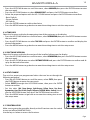
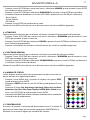
3.17 CONTROLLER IR
Make sure to point the controller directly at the IR receiver near the switch
to turn on/o the SMARTMODULA.
Use the keys as below to access the functions.
FADE
SOUND
SENSIT.
AUTO
MACRO
POWER
STROBESPEEDDIMMERMANUAL
AMBER
UV
RED
YELLOW
CYAN
MAGENTA
STATIC
DEEP
ORANGE
LIGHT
ORANGE
SEA
GREEN
AQUA
MARINE
WARM
WHITE
COLD
WHITE
GREEN
BLUE VIOLET PURPLE
WHITE

SMARTMODULA
16
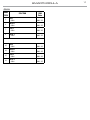
3.18 DMX CONTROL
1 CHANNEL
MODE
FUNCTION DMX
Value
1 Ch
1
WHITE
0~100% 000 - 255
5 CHANNELS
MODE
FUNCTION DMX
Value
5 Ch
1
DIMMER
0~100% 000 - 255
2
RED
0~100% 000 - 255
3
GREEN
0~100% 000 - 255
4
BLUE
0~100% 000 - 255
5
WHITE
0~100% 000 - 255
8 CHANNELS
MODE
FUNCTION DMX
Value
8 Ch
1
DIMMER
0~100% 000 - 255
2
RED
0~100% 000 - 255
3
GREEN
0~100% 000 - 255
4
BLUE
0~100% 000 - 255
5
WHITE
0~100% 000 - 255
6
VIRTUAL COLOR
No Function
Red
000 - 015
016 - 025
PIXCH
MODE
FUNCTION DMX
Value
PIXCH
1
DIMMER
0~100% 000 - 255
2
VIRTUAL COLOR
No Function
Red
Deep Orange
Light Orange
Light Orange
Yellow
Green
Sea Green
Aquamarine
Cyan
Blue
Violet
Purple
Magenta
Full RGB
White
Gradual
000 - 015
016 - 025
026 - 035
036 - 045
046 - 055
056 - 065
071 - 090
066 - 075
076 - 085
086 - 095
096 - 105
106 - 115
116 - 125
126 - 135
136 - 145
146 - 155
156 - 255
3
SHUTTER FUNCTION
Normal Shutter Function
Strobe eect slow to fast
000 - 031
032 - 255
4
DIMMER FADE
0~100%
000 - 255
6
Deep Orange
Light Orange
Light Orange
Yellow
Green
Sea Green
Aquamarine
Cyan
Blue
Violet
Purple
Magenta
Full RGB
White
Gradual
026 - 035
036 - 045
046 - 055
056 - 065
071 - 090
066 - 075
076 - 085
086 - 095
096 - 105
106 - 115
116 - 125
126 - 135
136 - 145
146 - 155
156 - 255
7
SHUTTER FUNCTION
Normal Shutter Function
Strobe eect slow to fast
000 - 031
032 - 255
8
DIMMER FADE
0~100%
000 - 255

17
SMARTMODULA
PIXCH
MODE
FUNCTION DMX
Value
PIXCH
5
RED 1
0~100% 000 - 255
6
GREEN 1
0~100% 000 - 255
7
BLUE 1
0~100% 000 - 255
8
WHITE 1
0~100% 000 - 255
25
RED 6
0~100% 000 - 255
26
GREEN 6
0~100% 000 - 255
27
BLUE 6
0~100% 000 - 255
28
WHITE 6
0~100% 000 - 255

SMARTMODULA
18
- 4 - MAINTENANCE
4.1 MAINTENANCE AND CLEANING THE UNIT
• Make sure the area below the installation place is free from unwanted persons during setup.
• Switch o the unit, unplug the main cable and wait until the unit has cooled down.
• All screws used for installing the device and any of its parts should be tightly fastened and should not
be corroded.
• Housings, xations and installation spots (ceiling, trusses, suspensions) should be totally free from any
deformation.
• The main cables must be in impeccable condition and should be replaced immediately even when a
small problem is detected.
• It is recommended to clean the front at regular intervals, from impurities caused by dust, smoke, or
other particles to ensure that the light is radiated at maximum brightness. For cleaning, disconnect the
main plug from the socket. Use a soft, clean cloth moistened with a mild detergent. Then carefully wipe
the part dry. For cleaning other housing parts use only a soft, clean cloth. Never use a liquid, it might
penetrate the unit and cause damage to it.
4.2 FUSE REPLACEMENT
1. Disconnect this product from the power outlet.
2. Remove the safety cap by a screwdriver.
3. Replace the blown fuse with a fuse of the exact same type and rating.
4. Install the safety cap, and reconnect power.
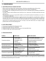
4.3 TROUBLESHOOTING
Problems Possible causes Checks and remedies
Fixture does not light up
• No mains supply
• Dimmer fader set to 0
• All color faders set to 0
• Faulty LED
• Faulty LED board
• Check the power supply voltage
• Increase the value of the dimmer channels
• Increase the value of the color channels
• Replace the LED board
• Replace the LED board
General low light intensity
• Dirty lens assembly
• Misaligned lens assembly
• Clean the xture regularly
• Install lens assembly properly
Fixture does not power up
• No power
• Loose or damaged power cord
• Faulty internal power supply
• Check for power on power outlet
• Check power cord
• Replace internal power supply
Fixture does not respond to DMX
• Wrong DMX addressing
• Damaged DMX cables
• Bouncing signals
• Check control panel and unit addressing
• Check DMX cables
• Install terminator as suggested
Contact an authorized service center in case of technical problems or not reported in the table can not be
resolved by the procedure given in the table.
La pagina sta caricando ...
La pagina sta caricando ...
La pagina sta caricando ...
La pagina sta caricando ...
La pagina sta caricando ...
La pagina sta caricando ...
La pagina sta caricando ...
La pagina sta caricando ...
La pagina sta caricando ...
La pagina sta caricando ...
La pagina sta caricando ...
La pagina sta caricando ...
La pagina sta caricando ...
La pagina sta caricando ...
La pagina sta caricando ...
La pagina sta caricando ...
La pagina sta caricando ...
La pagina sta caricando ...
La pagina sta caricando ...
La pagina sta caricando ...
La pagina sta caricando ...
La pagina sta caricando ...
La pagina sta caricando ...
La pagina sta caricando ...
-
 1
1
-
 2
2
-
 3
3
-
 4
4
-
 5
5
-
 6
6
-
 7
7
-
 8
8
-
 9
9
-
 10
10
-
 11
11
-
 12
12
-
 13
13
-
 14
14
-
 15
15
-
 16
16
-
 17
17
-
 18
18
-
 19
19
-
 20
20
-
 21
21
-
 22
22
-
 23
23
-
 24
24
-
 25
25
-
 26
26
-
 27
27
-
 28
28
-
 29
29
-
 30
30
-
 31
31
-
 32
32
-
 33
33
-
 34
34
-
 35
35
-
 36
36
-
 37
37
-
 38
38
-
 39
39
-
 40
40
-
 41
41
-
 42
42
-
 43
43
-
 44
44


ProLights SMARTMODULA Manuale utente
- Categoria
- Proiettori
- Tipo
- Manuale utente
in altre lingue
- English: ProLights SMARTMODULA User manual
Documenti correlati
-
ProLights 13W track mounted LED pinspot Manuale utente
-
-
-
-
-
-
-
