La pagina si sta caricando...

*5 (# '3
$BSPDMJFOUF
TFOUJUBNFOUF-BSJOHSB[JBNP
FDJDPOHSBUVMJBNPQFSMB
TDFMUBEB-FJGBӃB
*-$045365503&
%FBSDVTUPNFS
8FUIBOLZPVBOE
DPOHSBUVMBUFZPVPOZPVS
DIPJDF
5)&."/6'"$563&3
$I SFDMJFOUF$IFSDMJFOU
.FSDJFUTJODSFT
G MJDJUBUJPOT QPVS MF DIPJY
RVFWPVTBWF[GBJU
-&$0/4536$5&63
Fig. 1 - Abb. 1 - Afb. 1
!! IMPORTANTE !! !! IMPORTANT !!!! IMPORTANT !!
!
THIS APPLIANCE IS CONCEIVED
FOR DOMESTIC USE ONLY. THE
MANUFACTURER SHALL NOT IN
ANY WAY BE HELD RESPONSIBLE
FOR WHATEVER INJURIES OR DAMAGES ARE
CAUSED BY INCORRECT INSTALLATION OR
BY UNSUITABLE, WRONG OR ABSURD USE.
THIS APPLIANCE IS NOT
INTENDED FOR USE BY
PERSONS (INCLUDING
CHILDREN) WITH REDUCED
PHYSICAL, SENSORY OR MENTAL
CAPABILITIES, OR LACK OF
EXPERIENCE AND KNOWLEDGE,
UNLESS THEY HAVE BEEN GIVEN
SUPERVISION OR INSTRUCTION
CONCERNING USE OF THE APPLIANCE
BY A PERSON RESPONSIBLE FOR
THEIR SAFETY. CHILDREN SHOULD BE
SUPERVISED TO ENSURE THAT THEY
DO NOT PLAY WITH THE APPLIANCE.
QUESTO PRODOTTO È STATO
CONCEPITO PER UN IMPIEGO DI
TIPO DOMESTICO. IL COSTRUTTORE
DECLINA OGNI RESPONSABILITÀ
NEL CASO DI EVENTUALI DANNI A COSE O
PERSONE DERIVANTI DA UNA NON CORRETTA
INSTALLAZIONE O DA USO IMPROPRIO,
ERRONEO OD ASSURDO.
L’APPARECCHIO NON DEVE
ESSERE USATO DA PERSONE
(COMPRESI BAMBINI) CON
RIDOTTE CAPACITÀ FISICHE,
SENSORIALI O MENTALI, O DA PERSONE
CHE MANCANO DELL’ESPERIENZA E DELLE
CONOSCENZE NECESSARIE SE NON SOTTO
LA SUPERVISIONE O DIETRO ISTRUZIONI
SULL’USO DELL’APPARECCHIO DA PARTE
DI UNA PERSONA RESPONSABILE PER LA
LORO SICUREZZA. I BAMBINI DEVONO
ESSERE CONTROLLATI PER ASSICURARSI
CHE NON GIOCHINO CON L’APPARECCHIO.
CE PRODUIT EST CONÇU
EXCLUSIVEMENT POUR USAGE
DOMESTIQUE. LE CONSTRUCTEUR
DÉCLINE TOUTE RESPONSABILITÉ
POUR DOMMAGES ET BLESSURES CAUSÉES
PAR UNE INSTALLATION INCORRECTE OU PAR
UN USAGE IMPROPRE, ERRONÉ OU ABSURDE.
L’APPAREIL NE DOIT PAS ÊTRE
UTILISÉ PAR DES PERSONNES
(ENFANTS INCLUS) DISPOSANT DE
CAPACITÉS PHYSIQUES,
SENSORIELLES OU MENTALES RÉDUITES, OU
PAR DES PERSONNES N’AYANT PAS
L’EXPÉRIENCE OU LES CONNAISSANCES
REQUISES, SI CE N’EST SOUS LA SURVEILLANCE
D’UNE PERSONNE RESPONSABLE DE LEUR
SÉCURITÉ OU APRÈS AVOIR REÇU DE CELLE-CI
LES INSTRUCTIONS RELATIVES À L’UTILISATION
DE L’APPAREIL. LES ENFANTS DOIVENT ÊTRE
SURVEILLÉS, AFIN DE S’ASSURER QU’ILS NE
JOUENT PAS AVEC L’APPAREIL.
2
L’apparecchio deve essere
allacciato da personale
professionalmente
qualicato e in conformità
alla norme vigenti.
La targhetta (a) delle
caratteristiche del forno
è accessibile anche ad
apparecchio installato.
In questa targhetta,
visibile aprendo la
porta, sono riportati tutti
i dati di identicazione
dell’apparecchio, la
pressione e il tipo di gas per
il quale è stato regolato.
L’apparecchio essendo
da incasso appartiene alla
classe III.
Pertanto Vi invitiamo a
seguire attentamente le
istruzioni ed i suggerimenti
per un corretto utilizzo dei
nostri prodotti.
The appliance must be
connected by qualied
technician in accordance with
the applicable regulations.
The data plate (a) of the
oven is still visible after the
appliance has been installed.
This plate, which is visible
when the oven door is open,
contains all the identication
data of the appliance, as well
the type of gas and service
pressure for which it has
been calibrated.
Since the appliance is built-
in, it belongs to class III.
Follow the instructions and
suggestions carefully to
ensure the safe and proper
use of this product.
L’appareil doit être installé
par un personnel qualié
dans le respect des normes
en vigueur. La plaque (a) des
caractéristiques du four est
accessible appareil installé.
Sur cette plaque, visible en
ouvrant la porte, se trouvent
toutes les données de
l’appareil, la pression et le
type de gaz pour lequel il a
été réglé.
Cet appareil à encastrer
appartient à la classe III.
Nous vous invitons à suivre
attentivement les instructions
et les suggestions pour une
utilisation correcte de nos
produits.
La pagina si sta caricando...
La pagina si sta caricando...
La pagina si sta caricando...

IT GB FR
ISTRUZIONI PER
L’INSTALLATORE
NORME PER L’INSTALLAZIONE
DELL’APPARECCHIO
(ubicazione e ventilazione lo-
cale)
Le norme italiane che regolano
l’installazione, la manutenzione
e la conduzione degli
apparecchi a gas per uso
domestico sono le seguenti:
- UNI-CIG n. 7129
- UNI-CIG n. 7131
Riportiamo di seguito uno
stralcio di tali norme. Per tutte
le indicazioni non riportate è
necessario consultare le norme
citate.
UBICAZIONE:
(Fig. 2) gli apparecchi di cottura
devono sempre scaricare i
prodotti della combustione in
apposite cappe, che devono
essere collegate a camini,
canne fumarie o direttamente
all’esterno.
In caso non esista la possibilità
di applicazione della cappa, è
consentito l’impiego di un
elettroventilatore, installato su
finestra o su parete affacciata
sull’esterno, da mettere in
funzione contemporaneamente
all’apparecchio, purché siano
tassativamente rispettate le
norme inerenti la ventilazione.
VENTILAZIONE DEL
LOCALE:
(Fig. 2) è indispensabile che
nel locale in cui sono installati
degli apparecchi a gas possa
almeno affluire tanta aria
comburente quanta ne viene
richiesta dalla combustione del
gas consumato dai vari
apparecchi.
È quindi necessario, per
l’afflusso dell’aria nel locale,
praticare delle aperture che
rispondano ai requisiti
seguenti:
a) avere una sezione libera
totale di 6 cm
2
per ogni kW
con un minimo di 100 cm
2
(tali aperture possono
eventualmente essere
Fig. 2 - Abb. 2 - Afb. 2
INSTRUCTIONS FOR
THE INSTALLER
INSTRUCTIONS FOR
INSTALLATION OF THE
APPLIANCE (positioning and
ventilation requirements)
The regulations covering the
installation, maintenance and
operation of gas appliances for
domestic use are applicable
regulations.
An extract of these regulations
appears below. For all
indications not covered, refer to
the above-mentioned
regulations.
POSITIONING:
(Fig. 2) the products of
combustion from cooking
appliances must always be
discharged into suitable
extractor hoods, which must be
connected to a chimney, flue or
vented directly to outside the
building. In situations where it
is not possible to install an
extractor hood, an electric
extractor fan installed in a
window or external wall may be
used, provided that all
requirements of the ventilation
regulations are satisfied; the
fan should switch on whenever
the appliance is in operation.
VENTILATION:
(Fig. 2) it is essential that the
room in which gas appliances
are installed is adequately
ventilated to ensure that all the
appliances receive the required
quantity of fresh air for
combustion.
To ensure an adequate air
flow, it may be necessary to
create apertures in accordance
with the following
requirements:
a) with cross-sectional area of
6 cm
2
per kW with a
minimum cross-sectional
area of 100 cm
2
(these
apertures may also be
created by increasing the
INSTRUCTIONS POUR
L’INSTALLATEUR
NORMES D’INSTALLATION
DE L’APPAREIL
(emplacement et ventilation
locale)
Les normes d’installation,
d’entretien et de conduite des
appareils à gaz à usage
domestique sont les normes
en viguer.
Vous trouverez ci-dessous un
aperçu de ces textes. Pour
toutes les indications non
reportées consulter les textes
de référence.
EMPLACEMENT
(Fig. 2) Les appareils de
cuisson doivent toujours
évacuer les produits de
combustion dans des hottes ad
hoc, qui doivent être reliées à
des carneaux de fumées ou
directement à l’extérieur. En
cas d’impossibilité d’installation
de la hotte, utiliser un
électroventilateur installé sur la
fenêtre ou sur un mur orienté
vers l’extérieur, à démarrer
simultanément avec l’appareil,
à condition de respecter
impérativement les normes de
ventilation.
VENTILATION DU LOCAL
(Fig. 2) Il est indispensable que
le local d’installation des
appareils à gaz soit aéré en
quantité d’air suffisante pour la
combustion des gaz.
Il est donc indispensable de
pratiquer des ouvertures ad
hoc qui présentent les
caractéristiques suivantes:
a) avoir une section libre totale
de 6 cm
2
par kW avec un
minimum de 100 cm
2
(ces
ouvertures peuvent être
pratiquées en majorant les
ouvertures entre porte et
sol);
b) être situées dans la partie
basse d’une paroi externe,
6
La pagina si sta caricando...

IT GB FR
ricavate maggiorando la
fessura tra porta e
pavimento);
b) essere situate nella parte
bassa di una parete
esterna, preferibilmente
opposta a quella in cui si
trova l’evacuazione dei gas
combusti;
c) la loro posizione deve
essere scelta in modo tale
da evitare che possano
essere ostruite e, se
praticate sui muri esterni,
esse devono essere
protette con griglie, reti
metalliche ecc. poste sulla
faccia esterna del muro con
una sezione netta.
In caso nel locale sia installato
un elettroventilatore per
l’evacuazione dell’aria viziata,
le aperture per il ricambio d’aria
devono garantire un passaggio
d’aria di almeno 35 m
3
/h per
ogni kW di potenza installata in
ambiente.
ALLACCIAMENTO GAS
Il forno può funzionare a gas
naturale (metano) a gas liquido
(GPL), e può essere facilmente
eseguita la conversione da un
tipo all’altro di gas, come
descritto nei successivi capitoli.
L’allacciamento alla rete di
distribuzione deve essere
eseguito da personale
specializzato e secondo le
prescrizioni relative alle norme
UNI-CIG 7129, 7131.
Nel caso l’apparecchio venga
alimentato con gas liquido
(GPL) in bombola, deve essere
utilizzato un regolatore di
pressione conforme alla norma
UNI CIG 7432.
ALLACCIAMENTO DEL
TUBO METALLICO
L’allacciamento gas può
essere eseguito mediante un
tubo metallico rigido conforme
alla norma UNI 8863 fissato
saldamente al raccordo “G”
(Fig. 3), oppure, mediante un
tubo flessibile di acciaio
inossidabile a parete continua,
di cui alla norma UNI CIG 9891
con lunghezza max. 2 mt.
Il raccordo “G” e la guarnizione
gap between the bottom of
doors and the floor);
b) situated at the bottom of an
external wall, preferably
opposite the wall on which
combustion products are
extracted ;
c) the positions of the
apertures should selected
so as to avoid the possibility
of their being obstructed
and, if made in external
walls, they must be
protected with grilles, metal
meshes, etc. installed on
the outside face of the wall.
If an electric extractor fan for
the removal of foul air is
installed in the room, the
apertures provided for air
changes must allow a
ventilation rate of at least 35
m
3
/h per kW of power installed.
GAS CONNECTION
The oven is designed to
operate with both natural gas
(methane) and liquid gas
(LPG), and can be easily
converted from one type to
another following the
instructions given in the relative
section of this booklet.
Connection to the gas supply
must be carried out by qualified
technicians and in conformance
with the requirements.
If the appliance is to operate
with gas bottles (LPG), a
pressure regulator conforming
to the requirements.
RIGID PIPE
CONNECTION
Connection to the mains gas
supply may be made via a rigid
pipe firmly attached to the
fitting “G” (Fig. 3), or via a
flexible stainless steel
continuous-wall hose,
conforming with a maximum
length of 2 metres.
The fitting “G” and seal “C” are
supplied with the appliance,
and comply with standards.
de préférence opposée à
celle dans laquelle se trouve
l’évacuation des gaz brûlés;
c) leur position doit être choisie
de façon à éviter qu’elles
soient obstruées et, si
pratiquées sur des murs
externes, elles doivent être
protégées avec des grilles,
des réseaux métalliques
etc. placés sur la façade
externe du mur avec une
section nette.
Si le local est équipé d’un
électroventilateur d’évacuation
de l’air vicié, les ouvertures de
changement d’air doivent
garantir un passage d’air d’au
moins 35 m
3
/h par kW de
puissance installée dans le
local.
BRANCHEMENT DU GAZ
Le four peut fonctionner au gaz
naturel (méthane) ou liquide
(GPL). La conversion d’un gaz
à l’autre est facile, comme
expliqué dans les pages
suivantes. Le branchement au
réseau de distribution doit être
fait par une personne
compétente dans le respect
des normes.
Si l’appareil est alimenté en
gaz liquide (GPL) en bouteille,
utiliser un régulateur de
pression conforme à la norme.
BRANCHEMENT DU TUBE
MÉTALLIQUE
Le branchement du gaz doit
être effectué par tube
métallique rigide fixé
solidement au raccord “G” (Fig.
3) ou par flexible acier inox à
mur continu, d’une longueur
max. 2 mètres.
Le raccord “G” et le joint
d’étanchéité “C” sont fournis
comme accessoires avec
l’appareil et sont conformes
8
La pagina si sta caricando...

IT GB FR
di tenuta “C” sono forniti come
accessori assieme
all’apparecchio, e sono
conformi rispettivamente alle
norme UNI ISO 7/1 e UNI 9264.
Importante:
Per l’orientamento del raccordo
“G” operare con due chiavi.
Ottenuta la direzione voluta
bloccare energicamente il dado
“A” (Fig. 3).
Fig. 3 - Abb. 3 - Afb. 3
Important:
Use two wrenches to turn the
fitting “G” to the required
position. When the fitting is in
the desired position, firmly
tighten nut “A” (Fig. 3).
ATTENZIONE - IMPORTANTE:
Al termine delle operazioni
di collegamento dell’appa-
recchio alla rete di
distribuzione gas (o alla
bombola di gas liquido)
CONTROLLARE LA TENU-
TA dell’accoppiamento
con soluzione di acqua
saponata, mai con una
fiamma.
WARNING - IMPORTANT:
after connecting the
appliance to the gas
supply (or to the liquid gas
bottles) CHECK FOR
LEAKS at the union using
a solution of soapy water
(never use a naked flame).
aux normes.
Important
Pour l’orientation du raccord
“G” utiliser 2 clés. Une fois la
direction obtenue, bloquer
énergiquement avec l’écrou “A”
(Fig. 3).
ATTENTION - IMPORTANT:
à la fin des opérations de
branchement de l’appareil
au réseau de distribution
gaz (ou à la bouteille de
GPL) CONTRÔLER
L’ÉTANCHÉITÉ de l’accou-
plement avec solution
d’eau savonneuse, jamais
avec une flamme.
10
La pagina si sta caricando...

*5 (# '3
CONVERSIONE AD ALTRO
TIPO DI GAS
Prima della conversione ad
altro tipo di gas, accertatevi del
tipo per il quale l’apparecchio è
stato regolato. (etichetta
adesiva (Figura 1) applicata
sull’apparecchio).
Per il diametro dell’ugello
riferirsi alla tabella degli ugelli.
Sostituzione dell’ugello del
bruciatore inferiore
Rendere privo di tensione
l’apparecchio;
1) Estrarre la suola
copribruciatore (vedi
ESTRAZIONE DELLA
SUOLA pagina 42).
2) Svitare la vite di fissaggio
del bruciatore del forno ed
estrarre dal supporto
insieme all’elemento termico
e alla candela di
accensione. (Figura 5)
3) Togliere l’ugello dall’attacco
con una chiave a tubo da 7
(Figura 6)
4) Avvitare a fondo il nuovo
ugello (diametro impresso in
centesimi di millimetro
sull’ugello) facendo
attenzione all’inserimento
preciso del filetto.
5) Montare il bruciatore
procedendo in ordine
inverso rispetto a quanto
descritto al punto 2.
6) Reinserire la suola nella
7) Regolazione del minimo (vedi
istruzioni a pagina 16)
posizione giusta.
Fig. 5 - Abb. 5 - Afb. 5 Fig. 6 - Abb. 6 - Afb. 6
CONVERSION TO A
DIFFERENT TYPE OF GAS
Before converting the
appliance for operation with a
different gas type, check which
type of gas it is currently set to
operate with (adhesive label
(Figure 1) on appliance).
For the correct nozzle
diameter, refer to the relative
table in this booklet.
Disconnect the electrical
power supply to the appliance;
1) Remove the burner cover
Replacing the lower burner
nozzle
plate (
see REMOVAL OF
THE BURNER COVER
PLATE page 42).
2) Remove the screw securing
the oven burner and
withdraw the burner from
the support together with
the heat sensor and the
ignition spark plug. (Figure
5)
3) Remove the nozzle using a
7 mm box wrench (Figure 6)
4) Screw the new nozzle in
fully (diameter in hundredths
of millimetre stamped on the
nozzle), taking care not to
cross the thread.
5) Replace the burner
reversing the operations in
step 2 above.
6) Replace the cover plate.
7) Adjusting the minimum flame
(see instructions on page 16)
CONVERSION D
E TYPE DE
GAZ
Avant la conversion du gaz,
vérifier que le gaz actuel est
correctement réglé (étiquette
adhésive (Figure 1) appliquée
sur l’appareil).
Pour le diamètre du gicleur,
consulter la table des gicleurs.
Couper la tension;
1) Extraire la sole cache-
Remplacement du gicleur
du brûleur inférieur
brûleur (
voir EXTRACTION
sole page 42).
2) Dévisser la vis de fixation du
brûleur et extraire du
support avec l’élément
thermique et la bougie
d’allumage (Figure 5).
3) Retirer le gicleur de la
fixation avec une clé à
douille de 7 (Figure 6)
4) Visser à fond le nouveau
gicleur (diamètre en
centièmes de millimètres
sur le gicleur) en faisant
attention à l’insertion précise
du filetage.
5) Monter le brûleur en
procédant dans l’ordre
inverse du point 2.
6) Remettre en place la sole.
7) Réglage du minimum (voir
directives page 16)
12
La pagina si sta caricando...

IT GB FR
I diametri sono impressi
sull’ugello in centesimi di
millimetri.
The diameters in hundredths of
millimetre are stamped on the
nozzle.
Les diamètres sont imprimés
sur le gicleur en centièmes de
millimètres.
IT
Bruciatore Tipo di gas
Pressione
mbar
P.min/P.max
mbar
Portata termica
nominale in kW
Consumo
Ø iniettori
1/100mm
Forno G20 20 17/25 2,5 238 l/h 113
G30/G31 28-30/37 25/45 2,5 182 g/h 76
Grill G20 20 17/25 2,2 210 l/h 112
G30/G31 28-30/37 25/45 2,2 160 g/h 75
GB
IE
Burner Type of gas
Pressure
mbar
P.min/P.max
mbar
Eat Imput kW Consumption
Ø injectors
1/100mm
Oven G20 20 17/25 2,5 238 l/h 113
G30/G31 28-30/37 25/45 2,5 182 g/h 76
Grill G20 20 17/25 2,2 210 l/h 112
G30/G31 28-30/37 25/45 2,2 160 g/h 75
FR
Brûleur Type de gaz
Pression
mbar
P.min/P.max
mbar
Débit calorique
en kW
Consommation
Ø injecteurs
1/100mm
Four G20/G25 20/25 17/25 2,5 238 l/h 113
G25 25 20/30 2,5 238 l/h 113
G30/G31 28-30/37 25/45 2,5 182 g/h 76
Gril G20 20 17/25 2,2 210 l/h 112
G25 25 20/30 2,2 210 l/h 112
G30/G31 28-30/37 25/45 2,2 160 g/h 75
14
TABELLA DEGLI INIETTORI INJECTORS TABLE TABLE DES INJECTEURS
La pagina si sta caricando...

IT GB FR
4')1.#<+10'«&'.«/+0+/1
0'.« %#51« &'..#
%108'45+10'« #&« #.641
6+21«&+«)#5
(KI«««#DD«««#HD«
A
#&,756/'06« 1(« 6*'
/+0+/7/« 5'66+0)
(1..19+0)« %108'45+10
61«#«&+(('4'06«)#5«6;2'
4d).#)'«&7«/+0+/7/«'0
%#5« &'« %108'45+10« &'
)#<
Procedere allo smontaggio
del frontale:
- per il frontale inox svitare le
due viti di fissaggio posteriori
- per i frontali in vetro svitare
le due ghiere sotto la
manopola.
Conversione da gas
naturale a gas liquido
Dopo aver tolto il frontale, con
il cacciavite passare attraverso
il foro della parete anteriore
del cruscotto e ruotare a fondo
in senso orario la vite A di
regolazione (fig. A)
Conversione da gas
liquido a gas naturale
Dopo aver tolto il frontale,
accendere il forno con
termostato posizionato a
250°C per almeno 10-15
minuti. Ruotare quindi il
termostato nella posizione
di minimo. Quindi ruotare la
vite del bypass A in senso
antiorario fino a vedere una
fiamma ridotta ma stabile.
Verificare che con apertura/
Proceed to disassemble the
front panel:
- for the front panel, unscrew
the two rear fixing screws
- for glass fronts, unscrew
the two lock rings under the
knob.
Conversion from
natural gas to liquid gas
After removing the front
panel, insert the screwdriver
in the hole in the front wall
of the instrument panel and
turn regulation screw A (fig.
A) clockwise.
Conversion from
liquid gas to natural gas
After removing the front
panel, light the over with
thermostat set to 250 °C
for at least 10-15 minutes.
Then, turn the thermostat
to the minimum position.
Then turn the bypass screw
A counterclockwise until you
see a reduced by stable
flame.
Check that the flame does
Démonter le panneau frontal:
- pour le panneau frontal en
inox, dévisser les deux vis
de fixation postérieures
- pour le panneau frontal en
en verre, dévisser les deux
bagues sous le bouton.
Conversion du gaz
naturel au gaz liquide
Après avoir enlevé le panneau
frontal, passer le tournevis à travers
le trou de la paroi antérieure du
bandeau de commande et tourner
à fond en sens horaire la vis A de
réglage (fig. A)
Conversion du gaz
liquide au gaz naturel
Après avoir enlevé le
panneau frontal, allumer le
four en tournant le thermostat
sur250°C pendant 10-15
minutes au moins. Ensuite,
positionner le thermostat au
minimum et tourner la vis du
by-pass A en sens inverse
horaire jusqu’à ce que la
flamme soit réduite mais
stable.
16
La pagina si sta caricando...

*5 (# '3
Dopo la conversione ad un
altro tipo di gas bisogna
correggere la targhetta
dell’apparecchio con i nuovi
dati (tipo e pressione del gas).
(Fig. 1)
After converting the appliance to
a different type of gas,
remember to change the data
plate to one with the new data
(gas type and pressure). (Fig. 1).
bruciatore che si trova nella located at the top front of the brûleur qui se trouve sur
parte alta anteriore della oven cavity. l’avant du moufle.
muffola.
SOSTITUZIONE DELL’UGELLO
PER IL GRILL GAS
REPLACING THE GAS GRILL
NOZZLE
REMPLACEMENT DU GICLEUR
POUR LE GRILL A GAZ
Après la conversion corriger la
plaquette de l’appareil avec les
nouvelles données (type et
1) Svitare la vite di fissaggio del
1) Remove the burner screw
1) Dévisser la vis de fixation du
ugello che deve essere del
which must be of the diameter
gicleur, qui doit impérativement
diametro indicato nella
indicated in the table on
être de la taille indiquée au
tabella di pag. 14.
page 14.
tableau de la page 14.
4) Avvitare a "fondo" il nuovo
4) Fully tighten the new nozzle
4) Visser à fond le nouveau
bruciatore assieme ai suoi
with its heat elements. siège avec l’ensemble des
elementi termici.
éléments thermiques.
2) Estrarre dalla sua sede il
2) Remove the burner together
2) Extraire le brûleur de son
sua sede e fissarlo con la
it with the screw.
son siège et le fixer avec la
vite.
vis.
5) Reinserire il bruciatore nella
5) Put back the burner and secure
5) Réinstaller le brûleur dans
a tubo da 7mm.
7 mm socket wrench.
d’une clé à tube 7 mm.
3) Togliere l'ugello con la chiave
3) Remove the nozzle using the
3) Démonter le gicleur à l’aide
pression du gaz). (Fig. 1)
chiusura ripetute della
porta del forno, la fiamma
non si spenga. In caso di
spegnimento della fiamma
aumentare leggermente la
regolazione del minimo.
not go out when the door
of the oven is opened and
closed repeatedly. If the flame
goes out, slight increase the
minimum regulation setting.
Vérifier que la flamme ne
s’éteint pas en ouvrant/
fermant plusieurs fois la porte
du four. Le cas échéant,
augmenter légèrement le
réglage du minimum.
18
La pagina si sta caricando...

IT GB FR
ENCASTREMENT DU FOUR
Le four peut être installé
sous un plan de cuisson ou
dans une colonne. Les di-
mensions de l’encastrement
doivent être indiquées figure 7.
Le matériau avec lequel le
meuble est réalisé doit être
en mesure de résister à la
chaleur. Le four doit être
centré par rapport aux parois
du meuble et fixé avec les
vis et les douilles fournies à
cet effet.
Pour l’accouplement du four
avec des plans de cuisson
polyvalents de gaz (figure 8)
voir les instructions en
annexe du plan de cuisson.
FLUSH FITTING
The oven can be installed
under a work top or in a
cooking column. The
dimensions of the housing for
the oven are given in figure 7.
Make sure that surrounding
materials are heat resistant.
Align the oven centrally with
respect to the side walls of
the units surrounding it and
fix it in place with the screws
and Allen screws provided.
If a gas hob is to installed in
combination with the oven
refer to the instructions
supplied with the hob (figure
8).
INCASSO DEL FORNO
Il forno può essere installato
sotto un piano di cottura
oppure in colonna. Le di-
mensioni dell’incasso devo-
no essere come riportato in
figura 7.
Il materiale del mobile deve
essere in grado di resistere
al calore. Il forno deve esse-
re centrato rispetto alle pareti
del mobile e fissato con le
viti e bussole che sono
fornite in dotazione.
Per l’abbinamento del
forno con i piani di cottura
polivalenti gas (figura 8)
vedere le istruzioni
allegate al piano cottura.
Fig. 7 - Abb. 7 - Afb. 7
20
La pagina si sta caricando...

IT GB FR
BRANCHEMENT
ELECTRIQUE
Avant d’effectuer le bran-
chement électrique, s’assu-
rer que :
- les caractéristiques de l’in-
stallation permettent de re-
specter ce qui est indiqué
sur la plaque d’identifica-
tion qui est appliquée sur
le devant du four;
- l’installation est munie
d’un raccordement à la pri-
se de terre conforme aux
normes et aux dispositions
prévues par la loi. La mise
à la terre est obligatoire
aux termes de la loi.
Le câble ne doit en aucun
cas atteindre une
température supérieure de
plus de 50° C par rapport
à la température ambiante.
Si un appareil fixe n’a pas
de cordon d’alimentation
et de fiche ou d’autre
dispositif assurant la
déconnexion du secteur,
avec une distance
d’ouverture des contacts
permettant une
déconnexion complète
dans les conditions de la
ELECTRICAL
CONNECTIONS
Before connecting the oven
to the mains power supply,
make sure that:
- The supply voltage corre-
sponds to the
specifications on the data
plate on the front of the
oven.
- The mains supply has an
efficient earth (ground)
connection complying with
all applicable laws and re-
gulations. Correct earthing
(grounding) is a legal re-
quirement.
The power cable should
never reach a temperature
50° C above ambient tem-
perature at any point along
its length.
If a fixed appliance is not
provided with a power
cable and plug, or some
other device permitting it
to be disconnected from
the mains electricity
supply, with a gap
between the contacts big
enough to guarantee
class III overvoltage
protection, then such a
ALLACCIAMENTO
ELETTRICO
Prima di effettuare l’allaccia-
mento elettrico accertarsi
che:
- le caratteristiche dell’im-
pianto siano tali da soddi-
sfare quanto indicato sulla
targa matricola applicata
sul fronte del forno;
- l’impianto sia munito di un
efficace collegamento di
terra secondo le norme e
le disposizioni di legge in
vigore. La messa a terra è
obbligatoria a termini di
legge.
Il cavo in nessun punto
dovrà raggiungere una
temperatura superiore di
50° C quella ambiente.
Se un apparecchio fisso
non è provvisto di cavo di
alimentazione e di spina,
o di altro dispositivo che
assicuri la disconnessione
dalla rete, con una
distanza di apertura dei
contatti che consenta la
disconnessione completa
nelle condizioni della
categoria di
sovratensione III, tali
Fig. 9 - Abb. 9 - Afb. 9
22
La pagina si sta caricando...

IT GB FR
N.B. Le fabricant décline
toute responsabilité si les
indications présentées dans
ce document et les normes
adoptées habituellement en
matière de prévention des
accidents du travail ne sont
pas respectées.
N.B. The manufacturer de-
clines all responsibility for
damage or injury if the above
instructions and normal
safety precautions are not
respected.
N.B. Il costruttore declina
ogni responsabilità nel caso
che quanto sopra e le usuali
norme antinfortunistiche non
vengano rispettate.
dispositivi di
disconnessione devono
essere previsti nella rete
di alimentazione
conformemente alle
regole di installazione.
La presa o l’interruttore
onnipolare devono essere
facilmente raggiungibili
con l’apparecchiatura in-
stallata.
device must be fitted to
the power supply in
compliance with the
regulations governing
electrical installations.
The socket or switch must
be easily reachable with
the oven fully installed.
catégorie de surtension
III, ces dispositifs de
déconnexion doivent être
prévus dans le réseau
d’alimentation
conformément aux
normes d’installation.
La prise ou l’interrupteur
omnipolaire doit pouvoir
être atteint facilement
lorsque l’appareil est
installé.
24
La pagina si sta caricando...

IT GB FR
ISTRUZIONI PER
L’UTENTE
PRIMO UTILIZZO
Il forno va pulito a fondo con
acqua e sapone e risciac-
quato accuratamente. Per
togliere i telai laterali nei forni
con pareti lisce procedere
come illustrato in figura.
Riscaldare il forno per circa
20 minuti alla massima tem-
peratura; verranno così
eliminati tutti i residui grassi
di lavorazione che
potrebbero causare sgrade-
voli odori in fase di cottura.
INSTRUCTIONS
POUR L’UTILISATEUR
PREMIERE UTILISATION
Le four doit être nettoyé à
fond à l’eau et au savon,
puis rincé méticuleusement.
Pour enlever les cadres la-
téraux dans les fours à pa-
rois lisses, procéder comme
indiqué sur la figure.
Il convient de n’insérer la
nourriture que lorsque le four
a atteint la température
préétablie, c’est-à-dire quand
s’éteint le voyant lumineux.
INSTRUCTIONS
FOR THE USER
THE FIRST TIME YOU USE
THE OVEN
Clean the oven thoroughly
with soapy water and rinse
well. To remove the lateral
frames from smooth-walled
ovens, proceed as shown in
the figure.
Operate the oven for about
20 minutes at maximum
temperature to burn off all
traces of grease which might
otherwise create unpleasant
smells when cooking.
Important:
A titre de précaution, avant
d’effectuer toute opération
de nettoyage du four quelle
qu’elle soit, débrancher
toujours la fiche de la prise
de courant ou couper la ligne
d’alimentation de l’appareil.
Veiller à ne pas utiliser de
substances acides ou
alcalines (jus de citron,
vinaigre, sel, tomate, etc.).
Ne pas utiliser de produits à
base de chlore, acides ou
abrasifs, surtout pour le
nettoyage des parois
peintes.
Important:
As a safety precaution,
before cleaning the oven,
always disconnect the plug
from the power socket or the
power cable from the oven.
Do not use acid or alkaline
substances to clean the oven
(lemon juice, vinegar, salt,
tomatoes etc.). Do not use
chlorine based products,
acids or abrasive products to
clean the painted surfaces of
the oven.
Importante:
come precauzione di sicu-
rezza prima di procedere a
qualsiasi operazione di puli-
zia del forno staccare sem-
pre la spina della presa di
corrente o togliere la linea di
alimentazione dell’appa-
recchio. Inoltre evitare di u-
sare sostanze acide o alcali-
ne (succhi di limone, aceto,
sale, pomodori ecc.). Evitare
di usare prodotti a base di
cloro, acidi o abrasivi spe-
cialmente per la pulizia delle
pareti verniciate.
Fig. 10 - Abb. 10 - Afb. 10
26
La pagina si sta caricando...

IT GB FR
PANNEAUX
AUTONETTOYANTS
CATALYTIQUES
Nos fours à parois lisses
peuvent être munis, à l’inté-
rieur, de panneaux auto-
nettoyants qui recouvrent les
parois.
Devant être accrochés sur
les parois, avant les châssis
latéraux, ces panneaux spé-
ciaux sont recouverts d’un
émail spécial catalytique mi-
croporeux qui provoque
l’oxydation et l’évaporation
graduelles des écla-
boussures d’huile et de
graisse qui sont ainsi éli-
minées pendant les cuissons
à plus de 200° C.
Si le four n’est pas propre
après la cuisson d’aliments
très gras, le faire fonctionner
à vide à la température
maximum pendant 60 mi-
nutes maximum.
Les panneaux autonet-
toyants ne doivent être ni
lavés, ni nettoyés avec des
produits abrasifs ou des
produits contenant des
acides ou des alcalis.
SELF-CLEANING
CATALYTIC PANELS
Our smooth walled ovens
can be fitted with self-
cleaning panels to cover the
inside walls.
These special panels are
simply hooked on to the
walls before the side frames
are fitted. They are coated in
a special, micro-porous ca-
talytic enamel which oxidises
and gradually vaporises
splashes of grease and oil at
cooking temperatures above
200° C.
If the oven is not clean after
cooking fatty foods, operate
the empty oven for 60 mi-
nutes (max.) at maximum
temperature.
Never wash or clean self-
cleaning panels with abra-
sive, acid, or alkaline
products.
PANNELLI AUTOPULENTI
CATALICI
I nostri forni con pareti lisce
hanno la possibilità di mon-
tare all’interno della muffola
dei pannelli autopulenti che
ricoprono le pareti.
Questi speciali pannelli, da
agganciare alle pareti prima
dei telai laterali, sono rico-
perti di uno speciale smalto
catalitico microporoso che
ossida e vaporizza gradual-
mente gli schizzi di olio e
grasso eliminandoli durante
le cotture sopra i 200° C.
Se dopo una cottura di cibi
molto grassi il forno non è
pulito, farlo funzionare a
vuoto alla massima tempera-
tura per un tempo massimo
di 60 minuti.
I pannelli autopulenti non de-
vono essere lavati né puliti
con prodotti abrasivi o pro-
dotti contenenti acidi o alcali.
Fig. 11 - Abb. 11 - Afb. 11
28
La pagina si sta caricando...

IT GB FR
DESCRIZIONE FRONTALE
COMANDI
FORNO A GAS CON GRILL
ELETTRICO
COMANDI (Fig. 12)
1. Termostato forno a gas
2. Manopola grill, girrarosto e
luce forno
3. Spia forno a gas
4. Contaminuti meccanico
5. Spia grill
TERMOSTATO DEL FORNO
Il termostato serve ad
impostare la temperatura
desiderata del forno ed è
completo di valvola di
sicurezza. Quando è in
funzione si illumina la spia
verde.
La posizione di minimo
corrisponde ad una
temperatura del forno di 130°C.
Essa dispone di una posizione
d’arresto.
La posizione “max” corrisponde
ad una temperatura del forno di
250°C, e costituisce la
posizione finale del termostato.
Per accendere il bruciatore,
premete la manopola del
termostato e ruotatela in senso
antiorario fino alla temperatura
desiderata.
Tenete premuta la manopola
per circa 5-10 secondi. Durante
questo tempo, il bruciatore
viene acceso elettricamente,
l’elemento termico viene
riscaldato e permette
l’erogazione di gas al
bruciatore.
Non azionate l’accensione per
Fig. 12 - Abb. 12 - Afb. 12
Fig. 13 - Abb. 13 - Afb. 13
DESCRIPTION OF THE
FRONT CONTROL PANEL
GAS OVEN WITH ELECTRIC
GRILL
CONTROLS (Fig. 12)
1. Gas oven temperature
control
2. Grill, spit roaster and oven
light knob
3. Gas oven indicator light
4. Mechanical timer
5. Grill indicator light
OVEN TEMPERATURE
CONTROL
The temperature control knob
serves to set the desired oven
temperature and is equipped
with a safety valve. When the
oven is in operation the green
light is illuminated.
The minimum position
corresponds to an oven
temperature of 130°C. The
control knob has stop in the
minimum position.
The “max” position
corresponds to an oven
temperature of 250°C, and is
obtained when the knob is
turned fully anticlockwise.
To light the burner, push in the
temperature control knob and
turn it anticlockwise to the
desired temperature.
Hold the knob pressed in for 5-
10 seconds. The burner will be
ignited electrically, and the
safety valve temperature
sensor will heat up thereby
allowing gas to continue to flow
to the burner.
Do not operate the ignition for
DESCRIPTION DU BANDEAU
DE COMMANDE
FOUR AU GAZ AVEC GRIL
ÉLECTRIQUE
COMMANDES (Fig. 12)
1. Thermostat four
2. Manette gril, broche et
éclairage
3. Voyant four
4. Minuterie mécanique
5. Voyant gril
THERMOSTAT DU FOUR
Le thermostat sert à
programmer la température
désirée du four, il est équipé
d’une soupape de sûreté.
Quand il fonctionne le voyant
est vert.
La position de minimum
correspond à une température
du four de 130°C. Elle dispose
d’une position d’arrêt.
La position “max” correspond à
une température du four de
250°C, et constitue la position
finale du thermostat. Pour
allumer le brûleur, appuyer la
manette du thermostat et la
tourner en sens antihoraire
jusqu’à la température voulue.
Appuyer la manette pendant 5-
10 secondes. Pendant ce
temps le brûleur est allumé
électriquement, l’élément
thermique est chauffé et
permet la distribution du gaz au
brûleur.
Ne pas actionner l’allumage
30
La pagina si sta caricando...

IT GB FR
più di 15 secondi. In caso di
mancata accensione del
bruciatore, tornate a premere
la manopola solo dopo aver
lasciato aperta la porta per
almeno 1 minuto.
Se l’accensione elettrica non
dovesse funzionare, avvicinare
un fiammifero acceso in
corrispondenza del foro che
permette di visualizzare il
bruciatore e contempora-
neamente premere la
manopola del termostato nella
posizione “max” per 5÷10
secondi.
GRILL ELETTRICO
Grill infrarosso: il forno è
provvisto di un regolatore di
energia. L’intensità di
irraggiamento della resistenza
grill può essere regolata da 1 a
MAX con l’apposita manopola
(Fig. 14). Quando la funzione
grill è inserita si accende la
spia e contemporaneamente la
luce interna del forno. Per far
funzionare il motorino
girarrosto si deve ruotare la
manopola fino al simbolo
e si avvertirà uno scatto.
Portare quindi la manopola alla
potenza desiderata, da
posizione 0 a 8.
ATTENZIONE: Il grill non
funziona quando è inserita la
funzione gas del forno.
CONTAMINUTI MECCANICO
Il contaminuti è un avvisatore
acustico a tempo, indipendente
dal funzionamento del forno,
che può essere regolato per un
periodo massimo di 60 minuti.
La manopola di regolazione
(Fig. 15) deve essere ruotata in
senso orario fino alla posizione
60 minuti e poi posizionata
ruotandola in senso antiorario
facendo coincidere l’indice con
il tempo desiderato.
Trascorso il tempo stabilito
interviene un segnale acustico
che cessa automaticamente.
Fig. 14 - Abb. 14 - Afb. 14
Fig. 15 - Abb. 15 - Afb. 15
longer than 15 seconds. If the
burner fails to ignite, leave the
door open for at least one
minute, then try again.
If the electrical ignition fails to
produce a spark, hold a lit taper
or match near the burner
inspection hole and press and
hold the temperature control
knob in the “max” position for 5
to 10 seconds.
ELECTRIC GRILL
Infrared grill: equipped with an
energy regulator. The heat
intensity of the grill can be set
from 1 to MAX using the
relative control knob (Fig. 14).
When the grill is in operation,
the grill indicator light and the
oven interior light will be
illuminated. To operate the spit
roaster motor, turn the knob to
the symbol
until you feel a
click. Then turn the knob to
desired power setting from 0 to
8.
WARNING: The grill will not
operate when the oven is on.
MECHANICAL MINUTE TIMER
The minute timer can be set to
a maximum time of 60
minutes; it emits an alarm tone
when the set time period has
elapsed. The minute timer
operates independently of the
oven.
The timer knob (Fig. 15) must
first be turned clockwise to the
60 minute position and then
turned anti-clockwise to the
desired time setting.
When the set time has elapsed,
the alarm will sound. The alarm
tone will stop automatically
after a certain period.
pendant plus de 15 secondes.
En cas d’absence de brûleur,
appuyer la manette après avoir
laissé ouverte la porte pendant
1 minute.
Si l’allumage électrique ne
fonctionne pas, approcher une
allumette allumée du regard de
visualisation du brûleur et
appuyer la manette du
thermostat dans la position
“max” pendant 5÷10 secondes.
GRIL ÉLECTRIQUE
Gril infrarouge: le four est
équipé d’un régulateur
d’énergie. L’intensité
d’irradiation de la résistance gril
peut être réglée de 1 à MAX
avec la manette (Fig. 14).
Quand la fonction gril est
insérée le voyant s’allume et
simultanément l’éclairage
interne du four. Pour faire
fonctionner le moteur de la
broche tourner la manette
jusqu’au symbole , on
entend un déclic. Porter la
manette à la puissance voulue,
de 0 à 8.
ATTENTION: le gril ne
fonctionne pas quand est
insérée la fonction gaz du four.
MINUTERIE MÉCANIQUE
La minuterie est un avertisseur
acoustique temporisé,
indépendant du
fonctionnement du four, qui
peut être réglé pendant 60
minutes maximum.
La manette de réglage (Fig.
15) doit être tournée en sens
horaire jusqu’à la position 60
minutes, et en sens inverse
jusqu’au temps voulu.
A la fin du temps fixé une
sonnerie se déclenche et
cesse automatiquement.
IT GB FR
più di 15 secondi. In caso di
mancata accensione del
bruciatore, tornate a premere
la manopola solo dopo aver
lasciato aperta la porta per
almeno 1 minuto.
Se l’accensione elettrica non
dovesse funzionare, avvicinare
un fiammifero acceso in
corrispondenza del foro che
permette di visualizzare il
bruciatore e contempora-
neamente premere la
manopola del termostato nella
posizione “max” per 5÷10
secondi.
GRILL ELETTRICO
Grill infrarosso: il forno è
provvisto di un regolatore di
energia. L’intensità di
irraggiamento della resistenza
grill può essere regolata da 1 a
MAX con l’apposita manopola
(Fig. 14). Quando la funzione
grill è inserita si accende la
spia e contemporaneamente la
luce interna del forno. Per far
funzionare il motorino
girarrosto si deve ruotare la
manopola fino al simbolo
e si avvertirà uno scatto.
Portare quindi la manopola alla
potenza desiderata, da
posizione 0 a 8.
ATTENZIONE: Il grill non
funziona quando è inserita la
funzione gas del forno.
CONTAMINUTI MECCANICO
Il contaminuti è un avvisatore
acustico a tempo, indipendente
dal funzionamento del forno,
che può essere regolato per un
periodo massimo di 60 minuti.
La manopola di regolazione
(Fig. 15) deve essere ruotata in
senso orario fino alla posizione
60 minuti e poi posizionata
ruotandola in senso antiorario
facendo coincidere l’indice con
il tempo desiderato.
Trascorso il tempo stabilito
interviene un segnale acustico
che cessa automaticamente.
Fig. 14 - Abb. 14 - Afb. 14
Fig. 15 - Abb. 15 - Afb. 15
longer than 15 seconds. If the
burner fails to ignite, leave the
door open for at least one
minute, then try again.
If the electrical ignition fails to
produce a spark, hold a lit taper
or match near the burner
inspection hole and press and
hold the temperature control
knob in the “max” position for 5
to 10 seconds.
ELECTRIC GRILL
Infrared grill: equipped with an
energy regulator. The heat
intensity of the grill can be set
from 1 to MAX using the
relative control knob (Fig. 14).
When the grill is in operation,
the grill indicator light and the
oven interior light will be
illuminated. To operate the spit
roaster motor, turn the knob to
the symbol
until you feel a
click. Then turn the knob to
desired power setting from 0 to
8.
WARNING: The grill will not
operate when the oven is on.
MECHANICAL MINUTE TIMER
The minute timer can be set to
a maximum time of 60
minutes; it emits an alarm tone
when the set time period has
elapsed. The minute timer
operates independently of the
oven.
The timer knob (Fig. 15) must
first be turned clockwise to the
60 minute position and then
turned anti-clockwise to the
desired time setting.
When the set time has elapsed,
the alarm will sound. The alarm
tone will stop automatically
after a certain period.
pendant plus de 15 secondes.
En cas d’absence de brûleur,
appuyer la manette après avoir
laissé ouverte la porte pendant
1 minute.
Si l’allumage électrique ne
fonctionne pas, approcher une
allumette allumée du regard de
visualisation du brûleur et
appuyer la manette du
thermostat dans la position
“max” pendant 5÷10 secondes.
GRIL ÉLECTRIQUE
Gril infrarouge: le four est
équipé d’un régulateur
d’énergie. L’intensité
d’irradiation de la résistance gril
peut être réglée de 1 à MAX
avec la manette (Fig. 14).
Quand la fonction gril est
insérée le voyant s’allume et
simultanément l’éclairage
interne du four. Pour faire
fonctionner le moteur de la
broche tourner la manette
jusqu’au symbole
, on
entend un déclic. Porter la
manette à la puissance voulue,
de 0 à 8.
ATTENTION: le gril ne
fonctionne pas quand est
insérée la fonction gaz du four.
MINUTERIE MÉCANIQUE
La minuterie est un avertisseur
acoustique temporisé,
indépendant du
fonctionnement du four, qui
peut être réglé pendant 60
minutes maximum.
La manette de réglage (Fig.
15) doit être tournée en sens
horaire jusqu’à la position 60
minutes, et en sens inverse
jusqu’au temps voulu.
A la fin du temps fixé une
sonnerie se déclenche et
cesse automatiquement.
IT GB FR
più di 15 secondi. In caso di
mancata accensione del
bruciatore, tornate a premere
la manopola solo dopo aver
lasciato aperta la porta per
almeno 1 minuto.
Se l’accensione elettrica non
dovesse funzionare, avvicinare
un fiammifero acceso in
corrispondenza del foro che
permette di visualizzare il
bruciatore e contempora-
neamente premere la
manopola del termostato nella
posizione “max” per 5÷10
secondi.
GRILL ELETTRICO
Grill infrarosso: il forno è
provvisto di un regolatore di
energia. L’intensità di
irraggiamento della resistenza
grill può essere regolata da 1 a
MAX con l’apposita manopola
(Fig. 14). Quando la funzione
grill è inserita si accende la
spia e contemporaneamente la
luce interna del forno. Per far
funzionare il motorino
girarrosto si deve ruotare la
manopola fino al simbolo
e si avvertirà uno scatto.
Portare quindi la manopola alla
potenza desiderata, da
posizione 0 a 8.
ATTENZIONE: Il grill non
funziona quando è inserita la
funzione gas del forno.
CONTAMINUTI MECCANICO
Il contaminuti è un avvisatore
acustico a tempo, indipendente
dal funzionamento del forno,
che può essere regolato per un
periodo massimo di 60 minuti.
La manopola di regolazione
(Fig. 15) deve essere ruotata in
senso orario fino alla posizione
60 minuti e poi posizionata
ruotandola in senso antiorario
facendo coincidere l’indice con
il tempo desiderato.
Trascorso il tempo stabilito
interviene un segnale acustico
che cessa automaticamente.
Fig. 14 - Abb. 14 - Afb. 14
Fig. 15 - Abb. 15 - Afb. 15
longer than 15 seconds. If the
burner fails to ignite, leave the
door open for at least one
minute, then try again.
If the electrical ignition fails to
produce a spark, hold a lit taper
or match near the burner
inspection hole and press and
hold the temperature control
knob in the “max” position for 5
to 10 seconds.
ELECTRIC GRILL
Infrared grill: equipped with an
energy regulator. The heat
intensity of the grill can be set
from 1 to MAX using the
relative control knob (Fig. 14).
When the grill is in operation,
the grill indicator light and the
oven interior light will be
illuminated. To operate the spit
roaster motor, turn the knob to
the symbol
until you feel a
click. Then turn the knob to
desired power setting from 0 to
8.
WARNING: The grill will not
operate when the oven is on.
MECHANICAL MINUTE TIMER
The minute timer can be set to
a maximum time of 60
minutes; it emits an alarm tone
when the set time period has
elapsed. The minute timer
operates independently of the
oven.
The timer knob (Fig. 15) must
first be turned clockwise to the
60 minute position and then
turned anti-clockwise to the
desired time setting.
When the set time has elapsed,
the alarm will sound. The alarm
tone will stop automatically
after a certain period.
pendant plus de 15 secondes.
En cas d’absence de brûleur,
appuyer la manette après avoir
laissé ouverte la porte pendant
1 minute.
Si l’allumage électrique ne
fonctionne pas, approcher une
allumette allumée du regard de
visualisation du brûleur et
appuyer la manette du
thermostat dans la position
“max” pendant 5÷10 secondes.
GRIL ÉLECTRIQUE
Gril infrarouge: le four est
équipé d’un régulateur
d’énergie. L’intensité
d’irradiation de la résistance gril
peut être réglée de 1 à MAX
avec la manette (Fig. 14).
Quand la fonction gril est
insérée le voyant s’allume et
simultanément l’éclairage
interne du four. Pour faire
fonctionner le moteur de la
broche tourner la manette
jusqu’au symbole , on
entend un déclic. Porter la
manette à la puissance voulue,
de 0 à 8.
ATTENTION: le gril ne
fonctionne pas quand est
insérée la fonction gaz du four.
MINUTERIE MÉCANIQUE
La minuterie est un avertisseur
acoustique temporisé,
indépendant du
fonctionnement du four, qui
peut être réglé pendant 60
minutes maximum.
La manette de réglage (Fig.
15) doit être tournée en sens
horaire jusqu’à la position 60
minutes, et en sens inverse
jusqu’au temps voulu.
A la fin du temps fixé une
sonnerie se déclenche et
cesse automatiquement.
IT GB FR
più di 15 secondi. In caso di
mancata accensione del
bruciatore, tornate a premere
la manopola solo dopo aver
lasciato aperta la porta per
almeno 1 minuto.
Se l’accensione elettrica non
dovesse funzionare, avvicinare
un fiammifero acceso in
corrispondenza del foro che
permette di visualizzare il
bruciatore e contempora-
neamente premere la
manopola del termostato nella
posizione “max” per 5÷10
secondi.
GRILL ELETTRICO
Grill infrarosso: il forno è
provvisto di un regolatore di
energia. L’intensità di
irraggiamento della resistenza
grill può essere regolata da 1 a
MAX con l’apposita manopola
(Fig. 14). Quando la funzione
grill è inserita si accende la
spia e contemporaneamente la
luce interna del forno. Per far
funzionare il motorino
girarrosto si deve ruotare la
manopola fino al simbolo
e si avvertirà uno scatto.
Portare quindi la manopola alla
potenza desiderata, da
posizione 0 a 8.
ATTENZIONE: Il grill non
funziona quando è inserita la
funzione gas del forno.
CONTAMINUTI MECCANICO
Il contaminuti è un avvisatore
acustico a tempo, indipendente
dal funzionamento del forno,
che può essere regolato per un
periodo massimo di 60 minuti.
La manopola di regolazione
(Fig. 15) deve essere ruotata in
senso orario fino alla posizione
60 minuti e poi posizionata
ruotandola in senso antiorario
facendo coincidere l’indice con
il tempo desiderato.
Trascorso il tempo stabilito
interviene un segnale acustico
che cessa automaticamente.
Fig. 14 - Abb. 14 - Afb. 14
Fig. 15 - Abb. 15 - Afb. 15
longer than 15 seconds. If the
burner fails to ignite, leave the
door open for at least one
minute, then try again.
If the electrical ignition fails to
produce a spark, hold a lit taper
or match near the burner
inspection hole and press and
hold the temperature control
knob in the “max” position for 5
to 10 seconds.
ELECTRIC GRILL
Infrared grill: equipped with an
energy regulator. The heat
intensity of the grill can be set
from 1 to MAX using the
relative control knob (Fig. 14).
When the grill is in operation,
the grill indicator light and the
oven interior light will be
illuminated. To operate the spit
roaster motor, turn the knob to
the symbol
until you feel a
click. Then turn the knob to
desired power setting from 0 to
8.
WARNING: The grill will not
operate when the oven is on.
MECHANICAL MINUTE TIMER
The minute timer can be set to
a maximum time of 60
minutes; it emits an alarm tone
when the set time period has
elapsed. The minute timer
operates independently of the
oven.
The timer knob (Fig. 15) must
first be turned clockwise to the
60 minute position and then
turned anti-clockwise to the
desired time setting.
When the set time has elapsed,
the alarm will sound. The alarm
tone will stop automatically
after a certain period.
pendant plus de 15 secondes.
En cas d’absence de brûleur,
appuyer la manette après avoir
laissé ouverte la porte pendant
1 minute.
Si l’allumage électrique ne
fonctionne pas, approcher une
allumette allumée du regard de
visualisation du brûleur et
appuyer la manette du
thermostat dans la position
“max” pendant 5÷10 secondes.
GRIL ÉLECTRIQUE
Gril infrarouge: le four est
équipé d’un régulateur
d’énergie. L’intensité
d’irradiation de la résistance gril
peut être réglée de 1 à MAX
avec la manette (Fig. 14).
Quand la fonction gril est
insérée le voyant s’allume et
simultanément l’éclairage
interne du four. Pour faire
fonctionner le moteur de la
broche tourner la manette
jusqu’au symbole , on
entend un déclic. Porter la
manette à la puissance voulue,
de 0 à 8.
ATTENTION: le gril ne
fonctionne pas quand est
insérée la fonction gaz du four.
MINUTERIE MÉCANIQUE
La minuterie est un avertisseur
acoustique temporisé,
indépendant du
fonctionnement du four, qui
peut être réglé pendant 60
minutes maximum.
La manette de réglage (Fig.
15) doit être tournée en sens
horaire jusqu’à la position 60
minutes, et en sens inverse
jusqu’au temps voulu.
A la fin du temps fixé une
sonnerie se déclenche et
cesse automatiquement.
32
AVVERTENZA: Nel caso
che, ruotando la manopola
del termostato, si noti un
comportamento anomalo
della stessa, chiudete il
rubinetto di mandata del gas
al forno e chiamate il centro
di assistenza più vicino.
WARNING: If you notice that
the thermostat is behaving
abnormally when you turn
the knob, close the tap that
sends gas to the oven and
call the nearest service
centre.
AVERTISSEMENT : Si,
en tournant le bouton du
thermostat, on remarque
un comportement anormal
de ce dernier, fermez le
robinet de refoulement du
gaz et appelez le centre
d’assistance le plus proche.
La pagina si sta caricando...

IT GB FR
DESCRIZIONE FRONTALE
COMANDI
FORNO A GAS CON GRILL
GAS
COMANDI (Fig. 16)
1. Termostato suola e grill gas
2. Manopola luce forno e
girarrosto
3. Spia forno a gas
4. Contaminuti meccanico
5. Spia funzionamento elettrico
TERMOSTATO DEL FORNO
Il termostato serve ad
impostare la temperatura
desiderata del forno ed è
completo di valvola di
sicurezza. Quando è in
funzione si illumina la spia
verde.
Per accendere il bruciatore
inferiore premete la manopola
del termostato e ruotatela in
senso antiorario fino alla
temperatura desiderata.
La posizione di minimo
corrisponde ad una
temperatura del forno di
130°C. Essa dispone di una
posizione d’arresto.
La posizione di massimo
corrisponde ad una
temperatura del forno di
250°C, e costituisce la
posizione finale del termostato.
Tenete premuta la manopola
per circa 5-10 secondi.
Durante questo tempo, il
bruciatore viene acceso
elettricamente, l’elemento
termico viene riscaldato e
permette l’erogazione di gas al
bruciatore.
Fig. 17 - Abb. 17 - Afb. 17
Fig. 16 - Abb. 16 - Afb. 16
DESCRIPTION OF THE
FRONT CONTROL PANEL
GAS OVEN WITH GAS
GRILL
CONTROLS (Fig. 16)
1. Lower burner and gas grill
temperature control knob
2. Oven and spit roaster
control knob light
3. Gas oven indicator light
4. Mechanical timer
5. Electrical indicator light
OVEN TEMPERATURE
CONTROL
The temperature control knob
serves to set the desired oven
temperature and is equipped
with a safety valve. When the
oven is in operation the green
light is illuminated.
To turn on the bottom burner,
push in the temperature control
knob and turn it anticlockwise
to the desired temperature.
The minimum position
corresponds to an oven
temperature of 130°C. The
control knob has stop in the
minimum position.
The maximum position
corresponds to an oven
temperature of 250°C, and is
obtained when the knob is
turned fully anticlockwise.
Hold the knob pressed in for 5-
10 seconds. The burner will be
ignited electrically, and the
safety valve temperature
sensor will heat up thereby
allowing gas to continue to flow
to the burner.
DESCRIPTION DU BANDEAU
DE COMMANDE
FOUR À GAZ AVEC GRIL
GAZ
COMMANDES (Fig. 16)
1. Thermostat sole et gril gaz
2. Manette éclairage et broche
3. Voyant four
4. Minuterie mécanique
5. Voyant fonctionnement
électrique
THERMOSTAT DU FOUR
Le thermostat sert à
programmer la température
désirée du four, il est équipé
d’une soupape de sûreté.
Quand il fonctionne le voyant
est vert.
Pour allumer le brûleur inférieur
appuyer la manette du
thermostat et la tourner en
sens antihoraire jusqu’à la
température voulue.
La position de minimum
correspond à une température
du four de 130°C. Elle dispose
d’une position d’arrêt.
La position de maximum
correspond à une température
du four de 250°C, et constitue
la position finale du thermostat.
Appuyer la manette pendant 5-
10 secondes. Pendant ce
temps le brûleur est allumé
électriquement, l’élément
thermique est chauffé et
permet la distribution du gaz au
brûleur.
34
La pagina si sta caricando...

*5 (# '3
GRILL GAS
)LGRILLAGAS$%6%FUNZIONARE
CONLAPORTASEMIAPERTAEDIL
PARACALOREDIPROTEZIONEFORNITO
INDOTAZIONEINSERITONELLE
FERITOIESOTTOILFRONTALECOMANDI
FRONTALECOMANDI
L’accensione si effettua
ruotando la manopola in senso
orario nella posizione
e tenendola premuta per 5 - 10
secondi.
LUCE FORNO - GIRARROSTO
Questo commutatore serve per
l’accensione della luce forno e
per il girarrosto nei modelli
dove è fornito.
Fig. 19 - Abb. 19 - Afb. 19
Fig. 18 - Abb. 18 - Afb. 18
GAS GRILL
4HEGASGRILL-534ONLYBE
OPERATED WITH OVEN DOOR
SLIGHTLY OPEN AND THE HEAT
SHIELDSUPPLIEDINSERTEDINTHE
SLOTSUNDERTHECONTROLPANEL
To turn on the grill, turn the
knob clockwise to the position
and hold it pressed in
for 5-10 seconds.
OVEN LIGHT - SPIT ROASTER
This knob is used to switch on
the oven interior light and the
spit roaster (on models so
equipped).
GRIL GAZ
,EGRILGAZ$/)4FONCTIONNER
AVECLAPORTEENTROUVERTEET
LÏCRANDEPROTECTIONTHERMIQUE
FOURNI INSÏRÏ DANS LES FENTES
SOUS LE BANDEAU DE
COMMANDE
L’allumage s’effectue en
tournant la manette en sens
horaire dans la position
en la tenant appuyée
pendant 5-10 secondes.
ÉCLAIRAGE FOUR - BROCHE
Ce commutateur sert à
l’allumage de l’éclairage du
four et la broche des modèles
équipés.
36
ATTENZIONE: quando si usa il
grill le parti accessibili possono
divenire calde, tenete i bambini
a debita distanza.
WARNING:
when using the grill,
accessible parts may become
hot, keep children at a safe
distance.
ATTENTION:
lorsqu’on utilise
le gril, les parties accessibles
peuvent devenir chaudes ; ne
pas laisser les enfants s’en
approcher.
La pagina si sta caricando...

VERSIONE VENTILATA
L'inserimento del solo
ventilatore farà circolare
all'interno del forno aria fredda
(ambiente), favorendo cosi' un
rapido scongelamento dei cibi
congelati.
La funzione ventilatore inserita
assieme al riscaldamento forte
proveniente dal bruciatore suola
permette la cottura dei cibi in
modo piu' delicato e uniforme
possibile rispetto al sistema
tradizionale con solo bruciatore
suola.
La cottura avviene piu'
rapidamente rispetto alla
cottura tradizionale. Il sistema
risulta idoneo per la cottura su
piu' ripiani ed anche
per cibi di
diversa natura (pesce, carne,
ecc...)
Con questa funzione non e'
necessario il preriscaldamento,
ma per pasticceria e' comunque
preferibile farlo.
VENTILATED VERSION
ventilator function turned on
together with the strong heat
coming from the bottom burner
makes it possible to cook foods
more evenly and delicately than
with the bottom burner alone.
Cooking is faster than in a
traditional oven. The system is
suitable for cooking foods of
different types (fish, meat etc)
on a number of levels.
Pre-heating
is not needed with
this function, but for cakes it is in
any case preferable.
VERSION VENTILEE
ventilateur seulement fera
circuler de l’air froid (ambiant) à
l’intérieur du four ce qui
favorisera ainsi une
décongélation plus rapide des
aliments congelés. La fonction
ventilateur insérée avec le
réchauffement fort provenant
du brûleur de sole permet la
cuisson des aliments de la
façon la plus délicate et
uniforme possible par rapport
au système traditionnel avec un
seul brûleur de sole. La cuisson
a eu lieu plus rapidement que la
cuisson traditionnelle. Le
système est approprié pour la
cuisson sur plusieurs niveaux et
même pour les aliments de
différente nature (poisson,
viande, etc...). Grâce à cette
fonction le préchauffage n’est
plus nécessaire, mais pour la
pâtisserie il est toutefois
conseillé de le faire.
0
I nostri forni da 60 cm a gas,
possono avere le varie
funzioni anche nella versione
ventilata.
Our 60cm gas ovens, also have
the various functions in the
ventilated version.
By turning on the ventilator
alone, cold air (room
temperature) circulates inside
the oven thus helping to rapidly
thaw frozen foods. The
Nos fours à gaz de 60 cm,
peuvent avoir différentes
fonctions même dans la version
ventilée. L'introduction du
38
La pagina si sta caricando...

SCONGELAMENTO
Selezionando una delle funzioni
di cottura ventilato e
regolando il termostato sullo
zero, il ventilatore farà
circolare all’interno del forno
aria fredda, favorendo
così un rapido scongelamento
dei cibi congelati.
DEFROSTING
By selecting one of the fan
cooking functions and setting
the thermostat to zero, the fan
allows cold air to circulate inside
the oven. In this way frozen
food can be rapidly defrosted.
DECONGELATION
En sélectionnant une des
fonctions de cuisson ventilée et
en réglant le ventilateur fera
circuler de l’air froid à l’intérieur
du
four, en provoquant de cette
manière une décongélation
rapide des aliments congelés.
0
*5 (# '3
CUISSON AU GRIL
VENTILATORE DI
RAFFREDDAMENTO
COOLING FAN
VENTILATEUR DE
REFROIDISSEMENT
Tipo di cottura per la
grigliatura o doratura dei
cibi. Alcuni forni possono
essere completi di motorino
asta e spiedo per cottura al
girarrosto.
La griglia con il cibo da
cuocere va inserito nella 1°
o 2° posizione da sopra.
Preriscaldare per 5’.
Ruotare la manopola del
termostato con
temperature da 1 a 8.
Il ventilatore e posto sulla
parte superiore del forno e
crea un circolo d’aria di
raf-freddamento all’interno
del mobile e attraverso la
porta del forno stesso.
Entra in funzione quando la
parte esteriore del forno
raggiunge i 60°C ca.
Accendendo il forno e
im-postando il termostato a
200°C, il ventilatore entra in
funzione dopo 10 min ca. Lo
spegnimento del ventilatore
avviene quando la parte
esteriore del forno scende
sotto i 60°C.
Dopo un utilizzo del forno a
200°C il ventilatore si
spe-gne dopo 30 min. ca.
The fan is positioned on the
upper part of the oven and
create a circle of cooling air
on the inside of the
furni-ture and through the
door of the oven.
It is turned on when the
temperature of the outer
shell of the oven reaches
60°C.
By switching on the oven
with the thermostat at 200°C
the fan starts working after
approx.10 min.
It is turned off when the
temperature of the outer
shell of the oven descends
under 60°C.
By switching off the oven
with the thermostat at 200°C
the fan stops working after
approx. 30 min.
Le ventilateur est place sur
la partie superieure du four
et cree une circulation d’air
de refroidissement a
l’interieur du meuble et a
travers la porte du four
luimeme. Il se met en
marche quand la partie
externe du four atteint
environ 60°C.
En allumant le four et en
programmant le thermostat
sur 200°C, le ventilateur se
met en marche apres 10
minutes environ.
L’extinction du ventilateur se
fait quand la partie externe
du four descend sous 60°C.
Apres une utilisation du four
a 200°C, le ventilateur
s’eteint apres environ 30
minutes.
COTTURA AL GRILL
Use the grill to grill or brown
foods.
Some ovens may be
equipped with an electric
motor, spit and skewers for
turning on the spit.
Place the shelf with the food
to be cooked in the 1st or
2nd position from the top.
Pre-heat the oven for 5
mi-nutes. Turn the
thermostat to a temperature
between 1 and 8.
Type de cuisson pour griller
ou dorer les aliments.
Certains fours peuvent etre
munis d’un moteur de
piques et d’une broche pour
la cuisson en rotissoire.
La grille portant l’aliment a
cuire doit etre inseree a la
1e ou 2e position du
dessus.Prechauffer pendant
5’.
Tourner le bouton du
ther-mostat sur une
temperature comprise entre
1 et 8.
GRILL COOKING
40
Il ventilatore e posto sulla
parte superiore del forno
e crea un circolo d’aria di
raffreddamento all’interno
del mobile che esce dalle
feritoie sotto il cruscotto
del forno. Entra in azione
ogni volta che si accende
il forno in tutte le funzioni.
Nell’eventualità che ciò non
accada, non accendete il
forno e chiamate il centro di
assistenza più vicino.
The fan is on top of the oven
and circulates cooling air
inside the cabinet, which
exits from the slots under the
control panel of the oven. It
turns on every time you turn
on the oven in all functions.
If this does not happen, do
not turn the oven on and call
the nearest service centre.
Le ventilateur est situé dans
la partie supérieure du four
et crée une recirculation
d’air de refroidissement
à l’intérieur du meuble,
s’échappant par les fentes
sous le tableau de bord
du four. Il se déclenche
chaque fois que vous
allumez le four, quelque
soit sa fonction. Dans cette
éventualité, n’allumez pas
le four et appelez le centre
d’assistance le plus proche.
La pagina si sta caricando...

*5 (# '3
PIETANZA
MAIN COURSE
ALIMENTS
PASTA BISCOTTO (ROTOLO)
GENOESE SPONGE (SWISS ROLL)
PÂTE BISCUITS (ROULÉS)
PASTA FROLLA (BISCOTTI)
SHORT PASTRY (BISCUITS)
PÂTE BRISÉE (BISCUIT)
PASTA CON LIEVITO ARTIFICIALE
(SCHIACCIATA)
DOUGH WITH RAISING AGENT
(SCHIACCIATA)
PÂTE À LEVAIN ARTIFICIEL
PAN DI SPAGNA (PICCOLO
FORME DI CARTA)
SPONGE CAKE (SMALL PAPER PASTRY
CASES)
PAIN D’ESPAGNE
PASTA LIEVITATA (STRUDEL
DI PAPAVERO)
LEAVENED DOUGH (STRUDEL)
PÂTE LEVÉE (STRUDEL)
PASTA SFOGLIA (SFOGLIATINE)
PUFF PASTRY (TARTLETS)
PÂTE FEUILLETÉE
SOUFFLÉ
SOUFFLÉ
SOUFFLÉ
SACHERTORTE
SACHERTORTE
SACHER TORTE
TORTA DI FRUTTA
FRUIT PIE
TARTE AUX FRUITS
PASTA PER BIGNÉ
CHOUX PASTRY
PÂTE À BEIGNETS
ARROSTO DI MANZO (CIRCA 1,5 KG)
ROAST BEEF (APPROX. 1.5 KG)
RÔTI DE BOEUF (ENV. 1,5 KG)
ARROSTO DI MAIALE (CIRCA 1,5 KG)
ROAST PORK (APPROX. 1.5 KG)
RÔTI DE PORC (ENV. 1,5 KG)
PIZZA
PIZZA
PIZZA
SFORMATO DI PESCE
BAKED FISH
QUICHE DE POISSON
SFORMATO DI VERDURE
BAKED VEGETABLES
GÂTEAU DE LÉGUMES
POLLAME
POULTRY
VOLAILLE
PRERISCALDARE
PREHEAT
PRÉCHAUFFER
si - Yes - OUI
si - Yes - OUI
si - Yes - OUI
si - Yes - OUI
si - Yes - OUI
si - Yes - OUI
si - Yes - OUI
si - Yes - OUI
si - Yes - OUI
si - Yes - OUI
si - Yes - OUI
si - Yes - OUI
si - Yes - OUI
si - Yes - OUI
si - Yes - OUI
si - Yes - OUI
TEMPERATURA
(oC)
TEMPERATURE
(
o
C)
TEMPÉRATURE
(oC)
210
200
200
190
180
190
180
180
160
200
200
200
200
180
170
190 - 200
TEMPO DI
COTTURA (min)
COOKING TIME
(min)
TEMPS DE
CUISSON (min)
15 - 20
10 - 12
25 - 30
20 - 25
40 - 50
20 - 30
35 - 40
55 - 60
160 - 180
35 - 40
90 - 120
100 - 120
20 - 25
50 - 60
30 - 40
60 - 70
CUOCERE AL FORNO
Scegliendo questa forma di
riscaldamento, potete usare il
forno come al solito e ricorrere
alle ricette dei libri di cucina.
Il piatto da cuocere deve
essere posto preferibilmente
nel piano centrale del forno.
COOKING IN THE OVEN
With this cooking method, you
can operate the oven in the
normal way and follow the
instructions in recipe books.
The food to be cooked should
preferably be placed on the
middle shelf of the oven.
CUISSON AU FOUR
En choisissant ce mode de
chauffage, vous pourrez utiliser
le four comme d’habitude et
utiliser les recettes.
Le plat à cuire doit être placé de
préférence sur le plan central du
four.
42
ATTENZIONE: L’uso prolungato
dell’apparecchio a gas produce
calore e umidità nella cucina.
Questo può richiedere una
ventilazione supplementare tipo
l’apertura di una nestra o una
ventilazione più efcace, per
esempio aumentando il livello
di ventilazione meccanica dove
presente (cappa aspirante).
WARNING: Prolonged use of
the gas appliance produces heat
and humidity in the kitchen. This
may require additional ventilation
such as opening a window or
more effective ventilation such
as by increasing the level of
mechanical ventilation where
present (extraction hood).
ATTENTION: L’usage prolongé
de l’appareil au gaz produit
de la chaleur et de l’humidité
dans la cuisine. Pour cela,
une ventilation supplémentaire
comme l’ouverture d’une fenêtre
ou une ventilation plus efcace,
par exemple en augmentant le
niveau de ventilation mécanique
si celle-ci est présente (hotte
aspirante).
La pagina si sta caricando...
La pagina si sta caricando...
La pagina si sta caricando...
La pagina si sta caricando...
La pagina si sta caricando...
La pagina si sta caricando...
La pagina si sta caricando...
La pagina si sta caricando...
La pagina si sta caricando...
La pagina si sta caricando...
La pagina si sta caricando...
La pagina si sta caricando...
La pagina si sta caricando...
La pagina si sta caricando...
-
 1
1
-
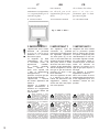 2
2
-
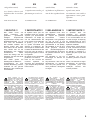 3
3
-
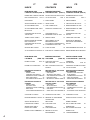 4
4
-
 5
5
-
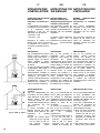 6
6
-
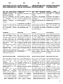 7
7
-
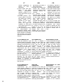 8
8
-
 9
9
-
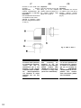 10
10
-
 11
11
-
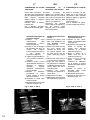 12
12
-
 13
13
-
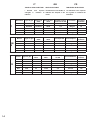 14
14
-
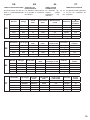 15
15
-
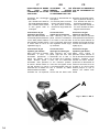 16
16
-
 17
17
-
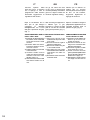 18
18
-
 19
19
-
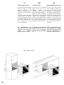 20
20
-
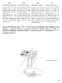 21
21
-
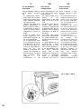 22
22
-
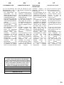 23
23
-
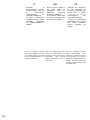 24
24
-
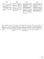 25
25
-
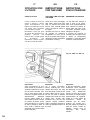 26
26
-
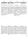 27
27
-
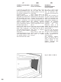 28
28
-
 29
29
-
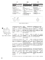 30
30
-
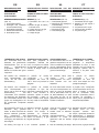 31
31
-
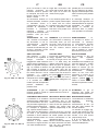 32
32
-
 33
33
-
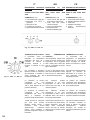 34
34
-
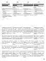 35
35
-
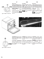 36
36
-
 37
37
-
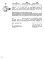 38
38
-
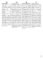 39
39
-
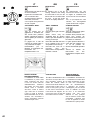 40
40
-
 41
41
-
 42
42
-
 43
43
-
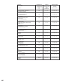 44
44
-
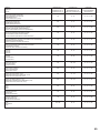 45
45
-
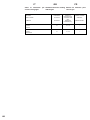 46
46
-
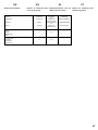 47
47
-
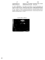 48
48
-
 49
49
-
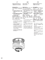 50
50
-
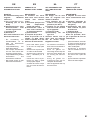 51
51
-
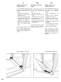 52
52
-
 53
53
-
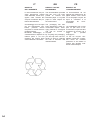 54
54
-
 55
55
-
 56
56


Candy OVG5053X Built In Single Gas Oven Manuale utente
- Tipo
- Manuale utente
- Questo manuale è adatto anche per
in altre lingue
- English: Candy OVG5053X Built In Single Gas Oven User manual
- français: Candy OVG5053X Built In Single Gas Oven Manuel utilisateur
- español: Candy OVG5053X Built In Single Gas Oven Manual de usuario
- Deutsch: Candy OVG5053X Built In Single Gas Oven Benutzerhandbuch
- Nederlands: Candy OVG5053X Built In Single Gas Oven Handleiding
- português: Candy OVG5053X Built In Single Gas Oven Manual do usuário
Documenti correlati
Altri documenti
-
Artusi AO750X Manuale utente
-
Whirlpool AKG 644/NB/02 Guida utente
-
-
-
-
Dometic OVN0250, OVG0250 Istruzioni per l'uso
-
-
Diamond G12-33 User and Installation Manual