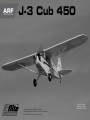
E-flite J-3 Cub 450 Manuale utente
- Categoria
- Giocattoli telecomandati
- Tipo
- Manuale utente
La pagina si sta caricando...
La pagina si sta caricando...
La pagina si sta caricando...

4
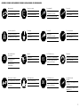
COME USARE IL MANUALE
Questo manuale è diviso in sezioni per rendere più facile la comprensione del montaggio. Vicino ad ogni passo sono
stati posti dei piccoli quadrati (
) per aiutare a tenere traccia delle cose fatte e di quelle da fare.
Questo è un prodotto di hobbistica sofisticato e NON un giocattolo. È necessario farlo funzionare con cautela e
responsabilità e avere conoscenze basilari di meccanica. Se questo prodotto non è utilizzato in maniera sicura e
responsabile potrebbero verificarsi lesioni odanni al prodotto stesso oad altre proprietà. Non è un prodotto adatto
aessere utilizzato dai bambini senza la diretta supervisione di un adulto. Non usare componenti non compatibili
o alterare il prodotto in nessuna maniera al di fuori delle istruzioni fornite da Horizon Hobby, Inc. Questo manuale
contiene le istruzioni per un funzionamento e una manutenzione sicuri. È fondamentale leggere e seguire tutte le
istruzioni e le avvertenze del manuale prima di montare, configurare ofar funzionare il Prodotto, al fine di utilizzarlo
correttamente e di evitare danni olesioni gravi.
AVVISO
Tutte le istruzioni, le garanzie e gli altri documenti pertinenti sono soggetti a cambiamenti a totale discrezione di
Horizon Hobby, Inc. Per una documentazione aggiornata sul prodotto, visitare il sito www.horizonhobby.com e fare
clic sulla sezione Support per questo prodotto.
Significato dei termini particolari
In tutta la documentazione relativa al prodotto sono utilizzati iseguenti termini per indicare vari livelli di potenziale
pericolo durante il funzionamento:
AVVISO: Procedure che, se non sono seguite correttamente, possono creare danni materiali E nessuna oscarsa
possibilità di lesioni.
ATTENZIONE: Procedure che, se non sono seguite correttamente, possono creare danni materiali E possibili
gravi lesioni.
AVVERTENZA: Procedure che, se non debitamente seguite, espongono alla possibilità di danni alla proprietà
fisica opossono omportare un’elevata possibilità di provocare ferite superficiali. Ulteriori precauzioni per la
sicurezza e avvertenze.
Almeno 14 anni. Non è un giocattolo.
AVVERTENZA: Leggere TUTTO il manuale di istruzioni e prendere familiarità con le caratteristiche del
prodotto, prima di farlo funzionare. Un utilizzo scorretto del prodotto può causare danni al prodotto stesso,
alle persone oalle cose, provocando gravi lesioni.
AVVERTIMENTI E PRECAUZIONI PER LA
SICUREZZA
Prima dell’uso leggere attentamente tutte le istruzioni
e le precauzioni per la sicurezza. In caso contrario si
potrebbero procurare incendi, danni o ferite.
Componenti
Usare solo componenti compatibili. Se ci fossero dubbi
riguardo alla compatibilità, è opportuno far riferimento
alle istruzioni relative al prodotto o ai componenti oppure
rivolgersi al reparto Horizon Hobby di competenza.
Volo
Per sicurezza volare solo in aree molto ampie. Meglio se
in campi volo autorizzati per modellismo. Consultare le
ordinanze locali prima di scegliere luogo dove volare.
Elica
Tenere gli oggetti liberi (vestiti, penne, cacciaviti, ecc.)
lontano dall’elica, prima che vi restino impigliati. Bisogna
fare attenzione anche con le mani perché c’è il rischio di
ferirsi anche gravemente.
Batterie
Quando si maneggiano o si utilizzano le batterie, bisogna
attenersi alle istruzioni del costruttore; il rischio è di
procurare incendi, specialmente con le batterie LiPo, con
danni e ferite serie.
Piccole parti
Questo kit comprende delle parti di piccole dimensioni
e non lo si può lasciare incustodito se c’è la presenza di
bambini che li possono inghiottire e rimanere soffocati o
intossicati.
RACCOMANDAZIONI PER OPERARE IN
SICUREZZA
• Controllare attentamente il modello prima di ogni volo
per accertarsi che sia idoneo.
• Essere consapevoli che un altro utente della frequenza
in uso, potrebbe procurare delle interferenze.
• Essere sempre cortesi e rispettosi nei confronti degli
altri utilizzatori dell’area in cui ci si trova.
• Scegliere un’area libera da ostacoli e abbastanza
ampia da permettere lo svolgimento del volo in
sicurezza.
• Prima del volo verificare che l’area sia libera da amici
e spettatori.
• Stare attenti alle altre attività che si svolgono in
vicinanza della vostra traiettoria di volo, per evitare
possibili conflitti.
• Pianificare attentamente il volo prima di lanciare il
modello.
• Rispettare sempre scrupolosamente le regole stabilite
dall’associazione locale.

5
15
30
OIL
L
R
L
R
x2
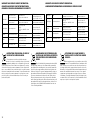
Use a pencil
Verwenden Sie einen Bleistift
Usare una matita
Use medium CA
Mittelflüssigen
Sekundenkleber verwenden
Usare colla ciano acrilica media
Use thin CA
Dünnflüssigen
Sekundenkleber verwenden
Usare colla ciano acrilica fine
Use a felt-tipped pen
Verwenden Sie einen Faserstift
Usare un pennarello
Use 15-minute epoxy
Verwenden Sie 15 Minuten Epoxy
Usare una resina epossidica con
indurimento di 15 minuti
Ensure free rotation
Rotation sicherstellen
Assicurarsi rotazione libera
Push tightly
Fest drücken
Spingere forte
Apply oil
Öl verwenden
Applicare olio
Attach temporarily
Vorübergehend anbringen
Attaccare temporaneamente
Apply threadlock
Schraubensicherungslack verwenden
Applicare fuido threadlock
Assemble right and left
Links und rechts montieren
Assemblare destra e sinistra
Repeat multiple times
(as indicated)
Vorgang wiederholen
(wie angezeigt)
Ripetere piu’ volte
(come indicato)
Ensure proper orientation
Ausrichtung/Richtung sicherstellen
Assicurarsi dell’appropriato
orientamento
Use 30-minute epoxy
Verwenden Sie 30 Minuten Epoxy
Usare una resina epossidica con
indurimento di 30 minuti
Fully tighten
Vollständig festziehen/festschrauben
Stringere al massimo
Use hobby knife with
#11 blade
Verwenden Sie ein Hobbymesser mit
# 11 Klinge
Usare taglierino per hobbistica con
lama numero 11
La pagina si sta caricando...

7
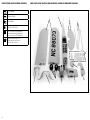
Part English Deutsch Italiano
1. EFL301001 Fuselage Rumpf Fusoliera
2. EFL301002 Wing Set Tragflächen Set Set ala
3. EFL301003 Tail Set Leitwerks Set Set coda
4. EFL301004 Landing Gear Set Fahrwerk Set del carrello di atterraggio
5. EFL301005 Cowling Motorhaube Carenatura
6. EFL301006 Windshields Scheibensatz Parabrezza
7. EFL301007 Strut Set Streben Set Set montante
8. EFL301010 Wheels 60mm Räder 60mm Ruote 60mm
9. EFL301012 Battery Hatch Akkuklappe Portello batteria
EFL301008 Hardware Set Zubehör Set dei pezzi
EFL301009 Pushrod Set Gestänge Set dell’asta di spinta
EFL301011 Decal Set Dekorbogen Set di decalcomanie
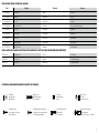
Flat Washer
Unterlegscheibe
Rondella piatta
Self-Tapping Screw
Selbstschneidene Schraube
Vite autofilettante
Self-Tapping Washer-Head Screw
Schraube mit Unterlegscheibenkopf
Vite autofilettante flangiata
Wheel collar
Stellring
Collare per le ruote
Brass pushrod connector
Gestängeanschluss
Nottolino in ottone per i comandi
Machine screw
Maschinenschraube
Vite per metallo
Setscrew
Madenschraube
Grano
Socket Head Cap Screw
Inbusschraube
Vite a brugola

8
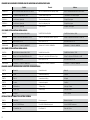
English Deutsch Italiano
SPMAR6115E AR6115e 6-Channel DSMX
®
Microlite Receiver: End Pin AR6115e 6 Kanal DSM X Microlite Empfänger, Endpin AR6115e 6-Canali DSMX
®
Microlite Ricevitore: End Pin
EFLRDS76 (4) 7.6-Gram DS76 Digital Sub-Micro Servo 7.6-Gram Sub-Micro Digital Servo 7.6-Gram DS76 Servo sub-micro digitale
EFLREX6L (2) 6 inch Extension, Lightweight 15cm Servoverlängerung, leicht Prolunga 15cm, leggera
EFLREX9L (2) 9 inch Extension, Lightweight 23cm Servoverlängerung, leicht Prolunga 23cm, leggera
EFLRYH3 3 inch Y-Harness, Lightweight Y-Kabel extraleicht Prolunga a Y 8cm, leggera
EFLM1400 Park 450 Brushless Outrunner Motor, 890Kv Park 450 BL AL-Motor Mtr,890kv Park 450 Motore Brushless, 890Kv
ELMA1030B 30-Amp Pro Switch-Mode BEC Brushless ESC (V2) 30-Amp Pro Switch-Mode BEC Brushless Regler (V2) 30-Amp Pro Regolatore (ESC) Brushless con BEC (V2)
APC10070E Electric Propeller, 10 x 7E Elektro Propeller, 10 x 7E Elica elettrica sottile, 10 x 7E
EFLB18003S30 1800mAh 3S 11.1V 30C LiPo,13AWG EC3
™
1800mAh 3S 11.1V 30C LiPo,13AWG EC3 1800mAh 3S 11.1V 30C LiPo,13AWG EC3
EFLM1500 Park 480 Brushless Outrunner Motor, 910Kv Park 480 BL AL-Motor910Kv Park 480 Motore Brushless, 910Kv
EFLA1040L 40-Amp Lite Pro Switch-Mode BEC Brushless ESC 40-Amp Lite Pro Switch-Mode BEC Brushless Regler 40-Amp Pro Regolatore (ESC) Brushless con BEC
APC12060E Electric Propeller, 12 x 6E Elektro Propeller, 12 x 6E Elica elettrica sottile, 12 x 6E
EFLB21003S30 2100mAh 3S 11.1V 30C LiPo, 13AWG EC3 2100mAh 3S 11.1V 30C LiPo,13AWG EC3 2100mAh 3S 11.1V 30C LiPo,13AWG EC3
PAAPT03 Medium CA Sekundenkleber mittel Medio CA
PAAPT09 Thin CA Sekundenkleber dünnflüssig Sottile CA
PAAPT20 Thick CA Sekundenkleber dickflüssig CA liquida
PAAPT42 Threadlock Schraubensicherungslack Frenafiletti
PAAPT35 15-Minute Epoxy 15 Minuten Epoxy Colla epoxy 15 minuti
PAAPT37 5-minute epoxy 5 Minuten Epoxy Colla epoxy 5 minuti
PAAPT56 Canopy glue Colla per capottine
EFLA110 Power Meter E-flite Lastmessgerät Misuratore di potenza
EFLC3020 Celectra
™
200W DC Charger E-flite 200W DC Multi-Akku Ladegerät Celectra 200W DC Caricabatterie
EFLA151 1/9 Civilian Pilot, Blue E-flite Zivilpilot 1/9 Pilota civile 1/9, blu

9
English Deutsch Italiano
Drill bit: 1/16-inch Bohrer: 1,5 mm Punte per trapano: 1,5 mm
Epoxy brushes Pinsel Spazzole epoxy
Felt-tipped pen Faserstift Pennarello
Hemostat Klemme Pinzetta
Hex wrench: 1.5mm, 3/32 inch Inbusschlüssel: 1,5mm, 3/32 inch Chiave esag.: 1,5mm, 3/32 inch
Hobby knife: #11 blade Hobbymesser mit # 11 Klinge Taglierino: #11 lama
Isopropyl alcohol Isopropyl Alkohol Alcol isopropilico
Low-tack tape Klebeband m. geringer Klebekraft Nastro a bassa aderenza
Mixing cups and sticks Mischbecher und Rührstäbchen Contenitori e stick per mixer colla
Paper towels Papiertücher Asciugamani di carta
Pencil Stift Matita
Phillips screwdriver: #0, #1 Phillips Schraubendreher: #0, #1 Cacciavite a croce: #0, #1
Pin vise Handbohrer Trapano manuale
Pliers Zange Pinze
Ruler Lineal Righello
Sandpaper Schleifpapier Carta vetrata
Scissors Schere Forbici
Side cutters Seitenschneider Lama laterale
Toothpicks Zahnstocher Stuzzicadenti
T-pins T- Nadeln Spilli a T

10
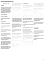
BEFORE STARTING ASSEMBLY
• Remove parts from bag.
• Inspect fuselage, wing panels, rudder and stabilizer for damage.
• If you find damaged or missing parts, contact your place of purchase.
If you find any wrinkles in the covering, use a heat gun (HAN100) and
covering glove (HAN150) or covering iron (HAN101) with a sealing iron sock
(HAN141) to remove them. Use caution while working around areas where
the colors overlap to prevent separating the colors.
• Charge transmitter and receiver batteries.
• Center trims and sticks on your transmitter.
• For a computer radio, create a model memory for this particular model.
• Bind your transmitter and receiver, using your radio system’s instructions.
IMPORTANT: Rebind the radio system once all control throws are set.
This will keep the servos from moving to their endpoints until the transmitter
and receiver connect. It will also guarantee the servo reversal settings are
saved in the radio system.
VOR DEM ZUSAMMENBAU
• Entnehmen Sie zur Überprüfung jedes Teil der Verpackung.
• Überprüfen Sie den Rumpf, Tragflächen, Seiten- und Höhenruder auf
Beschädigung.
• Sollten Sie beschädigte oder fehlende Teile feststellen, kontaktieren Sie
bitte den Verkäufer.
Zum Entfernen von Falten in der Bespannung verwenden Sie den Heißluftfön
(HAN100) und Bespannhandschuh (HAN150) oder das Folienbügeleisen
(HAN141). Bitte achten Sie bei überlappenden Farben, dass Sie diese sich
bei dem Bearbeitung nicht trennen.
• Laden des Senders und Empfängers.
• Zentrieren der Trimmungen und Sticks auf dem Sender.
• Sollten Sie einen Computersender verwenden, resetten Sie einen
Speicherplatz und benennen ihn nach dem Modell.
• Sender und Empfänger jetzt nach den Bindeanweisung des Herstellers zu
binden.
WICHTIG: Wir empfehlen dringend nachdem alle Einstellungen
vorgenommen worden sind, das Modell neu zu binden. Dieses verhindert,
dass die Servos in die Endanschläge laufen bevor sich Sender und Empfänger
verbunden haben. Es garantiert auch, dass die Servoreverseeinstellungen in
der RC Anlage gesichert sind.
PRIMA DI INIZIARE IL MONTAGGIO
• Togliere tutti i pezzi dalla scatola.
• Verificare che la fusoliera, l’ala e i piani di coda non siano danneggiati.
• Se si trovano parti danneggiate, contattare il negozio da cui è stato
acquistato.
Se si trovano delle pieghe nella ricopertura, si possono togliere usando una
pistola ad aria calda (HAN100) e guanto per ricopertura (HAN150), oppure
un ferro per ricopertura (HAN101) con la sua calza di protezione (HAN141).
Usare cautela quando si lavora in aree del rivestimento dove ci sono dei
colori sovrapposti, per evitare la loro separazione.
• Caricare il trasmettitore e la batteria di volo.
• Centrare stick e trim sul trasmettitore.
• Con una radio computerizzata creare una nuova memoria per questo
modello.
• Facendo riferimento alle istruzioni del radiocomando, connettere (bind)
trasmettitore e ricevitore.
IMPORTANTE: Ripetere la procedura di connessione una volta regolate
le corse, per evitare che i servi vadano a fine corsa. Garantirà anche che le
impostazioni di inversione del servo vengano salvate nel sistema radio.

11
1
L
R
L
R
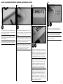
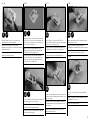
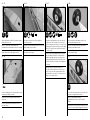
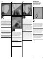
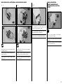
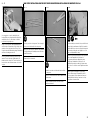
Use a pin vise and 1/16-inch (1.5mm) drill bit to drill a
hole in the center of each hinge slot. Prepare both the
aileron and wing at this time.
Bohren Sie mit einem 1,5-mm Handbohrer ein Loch in
die Mitte eines jeden Scharnierschlitzes in der rechten
und linken Tragfläche.
Usare una punta da 1,5mm per fare un foro al centro di
ogni fessura per la cerniera. Eseguire su entrambe le ali.
2
L
R
L
R
Remove the ailerons from the wing panel. Place a T-pin
in the center of each hinge. Slide the hinges into position
with the T-pin resting against the edge of the control
surface.
Nehmen Sie die Queruder von der Tragfläche ab. Stecken
Sie eine T-Nadel in die Mitte jedes Scharnieres. Schieben
Sie die Scharniere in die Schlitze und achten darauf, dass
die T-Nadel an der Kante des Ruders anliegt.
Rimuovere gli alettoni dal pannello delle ali. Posizionare
un perno a T al centro di ciascuna cerniera. Far scorrere
in posizione le cerniere con il perno a T appoggiato
contro il bordo della superficie di controllo.
3
L
R
L
R
Fit the aileron to the wing. Make sure the gap at each
end of the aileron is equal so the aileron can move freely.
Apply thin CA to the top and bottom of each hinge. Once
the CA cures, gently pull on the fixed surface and control
surface to make sure the hinges are glued securely. If
not, apply additional CA to secure each of the hinges.
Passen Sie das Querruder an der Tragfläche an. Bitte
stellen Sie sicher, dass der Spalt auf beiden Seiten gleich
groß ist und sich das Ruder frei bewegen kann. Geben
Sie dünnflüssigen Sekundenkleber auf die Ober- und
Unterseite jeden Scharnieres. Ziehen Sie nach dem
trocknen des Klebstoffes vorsichtig am Ruder um die
Klebung zu überprüfen. Kleben Sie bei Bedarf nach.
Appoggiare gli alettoni all’ala. Accertarsi che la fessura
sia uguale alle due estremità di ogni alettone, in modo
che possa muoversi liberamente. Applicare un po’ di
colla CA liquida sotto e sopra ad ogni cerniera. Intanto
che la colla asciuga, spingere con attenzione verso la
parte fissa per accertarsi che le cerniere siano incollate
bene. Se così non fosse, applicare dell’altra colla CA per
migliorare l’incollaggio delle cerniere.
4
L
R
L
R
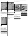
Trim the portion of the control horn that fits into the
aileron so it does not protrude through the top of the
aileron.
Kürzen Sie den Sockel des Ruderhorn wie abgebildet, so
dass es sich nicht durch die Unterseite durchdrückt.
Rifilare la porzione della squadretta che fuoriesce dalla
parte superiore dell’alettone.

12
5
L
R
L
R
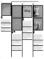
Check the fit of the control horn in the slot on the
aileron. Once fit, remove the horn and use thick CA to
glue the control horn tab and base in the aileron.
Überprüfen Sie im Schlitz die Passung des Ruderhornes.
Stimmt die Passung nehmen Sie es heraus und kleben
es mit dickflüssigen Sekundenkleber im Schlitz und am
Sockel ein.
Verificare che la squadretta si adatti bene nella sua
fessura. Quando è a posto toglierla e, usando della colla
CA, fissarla all’alettone.
1
L
R
L
R
x2
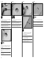
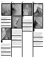
Remove the servo arms from the aileron servos. Prepare
the servo horns for the aileron servo by securing the
brass pushrod connectors in the servo arms using the
pushrod connector backplates. The connectors are
positioned 1/2 inch (13mm) from the center of the arm.
Nehmen Sie die Servoarme von den Querruderservos
ab. Stecken Sie die Gestängeanschlüsse in die
Arme und sichern diese mit den Rückplatten. Die
Gestängeanschlüsse werden 13mm von der Mitte des
Armes eingesetzt.
Togliere dai servi degli alettoni le loro squadrette e
prepararle fissando su di esse il nottolino in ottone
per collegare le barrette di comando. Il nottolino è
posizionato a 13mm dal centro della squadretta servo.
2
L
R
L
R
Center the aileron servos using the radio system. Install
the servo arms by rotating the arm 1 spline forward
from perpendicular on the servos. When installed,
the arm will lean toward the leading edge of the wing.
Prepare the right and left servo at this time.
Zentrieren Sie die Servos mit der Fernsteuerung.
Setzen Sie die Arme einen Zacken weiter nach vorne
als rechtwinklig ein. (Siehe Abildung) Nach Einbau, zeigt
der Servoarm nach vorne zur Tragflächenvorderkante.
Bereiten Sie beide Servos vor.
Centrare i servi usando il radiocomando. Montare la
squadretta sul servo ruotandola di una scanalatura in
avanti rispetto alla posizione perpendicolare al servo.
Quando è montata, la squadretta sarà inclinata verso il
bordo di entrata dell’ala. In questa fase preparare sia il
servo destro che quello sinistro.
3
L
R
L
R
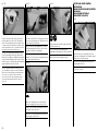
Place the servo on the servo cover, making sure the
arm angles toward the leading edge when the cover is
installed shown by the arrow in the photo. Center the
brass connector in the opening (photo 1), then center
the servo output in the opening (photo 2).
Setzen Sie das Servo auf die Abdeckung und achten bitte
darauf, dass der Servoarm bei eingesetzter Abdeckung
nach vorne zur Tragflächenvorderkante zeigt. Zentrieren
Sie den Gestängeanschluss in der Öffnung (Photo 1) und
danach den Servoabtrieb (Photo 2).
Sistemare il servo sul coperchio del suo supporto,
accertandosi che la squadretta sia rivolta verso il bordo
di entrata, prendendo come riferimento la freccia sulla
foto, poi centrare il servo rispetto alla fessura.

13
4
L
R
L
R
Mark the location of the servo on the cover for the
installation of the servo mounting blocks.
Markieren Sie die Position des Servos auf der
Abdeckung, so dass später passend dazu die Halteblöcke
geklebt werden können.
Segnare la posizione del servo sul coperchio per poi
installare i blocchetti di fissaggio.
5
L
R
L
R
5
Use epoxy to glue the 12 x 8 x 6mm servo mounting
blocks to the servo cover in the location marked in the
previous step. Use clamps or tape to hold the blocks in
position until the epoxy fully cures.
Kleben Sie die 12 x 8 x 6mm Halteblöcke an den
Markierungen. Fixieren Sie diese mit Klemmen oder
Klebeband bis das Epoxy ausgehärtet ist.
Incollare sul coperchio i blocchetti da 12x8x6mm
con colla epoxy nella posizione segnata prima. Usare
dei morsetti o del nastro adesivo per tenere fermi i
blocchetti mentre si asciuga la colla.
6
L
R
L
R
Fit the servo between the blocks. Mark the locations for
the servo mounting screws on the blocks.
Setzen Sie das Servo zwischen die Blöcke und markieren
die Positionen der Befestigungsschrauben.
Posizionare il servo tra i due blocchetti per segnare la
posizione delle viti di fissaggio.
7
L
R
L
R
Remove the servo. Use a pin vise and 1/16-inch
(1.5mm) drill bit to drill the holes in the servo mounting
blocks for the servo mounting screws.
Nehmen Sie das Servo heraus und bohren mit einem
1,5mm Bohrer die Löcher für die Servoschrauben.
Togliere il servo e, con una punta da 1,5mm, praticare i
fori sul blocchetto per le viti di fissaggio del servo.
8
L
R
L
R
Thread a servo mounting screw into each of the holes to
cut threads in the surrounding wood. Remove the screw
before proceeding.
Drehen Sie in jedes Servobefestigungsloch einmal eine
Servoschraube. Entfernen Sie die Schrauben bevor Sie
weiter machen.
Avvitare le viti di fissaggio per filettare il legno, poi
toglierle prima di procedere.
9
L
R
L
R
Apply a small amount of thin CA to harden the threads
made in the previous step.
Geben Sie einen kleinen Tropfen dünnflüssigen
Sekundenkleber in die Gewindelöcher um diese zu härten.
Mettere una piccola quantità di colla CA nei fori, per
indurire il filetto fatto nel passaggio precedente.
10
L
R
L
R
Secure the servo using the screws provided with the
servos.
Schrauben Sie das Servo mit den Schrauben aus dem
Lieferumfang des Servos fest.
Fissare il servo usando le sue viti.

14
11
L
R
L
R
Use dental floss or string to secure a 9-inch (228mm)
servo extension to the servo lead.
Sichern Sie eine 228mm Servoverlängerung an dem
Servokabel mit festem Garn oder Zahnseide.
Usare del filo interdentale o dello spago per fissare la
prolunga da 23cm al connettore del servo.
12
L
R
L
R
M2 x 10
x4
Thread a servo cover mounting screw into each of the
holes for the servo cover. Remove the screw before
proceeding.
Drehen Sie in jedes Loch der Servoabdeckung eine
Schraube. Entfernen Sie die Schrauben bevor Sie weiter
machen.
Avvitare le viti del coperchio nei loro fori e poi toglierle
prima di procedere.
13
L
R
L
R
Apply a small amount of thin CA to harden the threads
made in the previous step.
Geben Sie einen kleinen Tropfen dünnflüssigen
Sekundenkleber in die Gewindelöcher um diese zu härten.
Mettere una piccola quantità di colla CA nei fori, per
indurire il filetto fatto nel passaggio precedente.
14
L
R
L
R
Tie the string around the end of the 9-inch (228mm)
servo extension. Use the string to pull the servo
extension through the wing.
Knoten Sie eine Schnur um das Ende der 228mm
langen Servoverlängerung und ziehen mit der Schnur die
Verlängerung durch die Tragfläche.
Legare uno spago intorno al connettore della prolunga da
23cm per farla passare attraverso l’ala.
15
L
R
L
R
M2 x 10
x4
Secure the servo cover in the wing using the screws
listed.
Schrauben Sie die Servoabdeckung mit den aufgeführten
Schrauben fest.
Fissare il servo all’ala con le viti del coperchio.
La pagina si sta caricando...

16
4
L
R
L
R
15
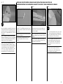
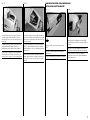
Separate the outer panel and center section and remove
the joiner. Apply epoxy to the joiner where it fits into the
wing center section. Make sure to apply epoxy to the
front and back of the joiner, as well as the edges of the
joiner.
Ziehen Sie Tragflächenmittelteil und Tragfläche
auseinander und nehmen den Verbinder heraus.
Streichen Sie Epoxy auf den Teil des Verbinders der in
das Tragflächenmittelteil gehört. Bitte achten Sie darauf
die Vorder- und Rückseite und die Kanten des Verbinders
mit Klebstoff einzustreichen.
Separare la semiala dal pianetto centrale e togliere
l’elemento di unione. Applicare la colla epoxy
sull’elemento di unione nella zona che entra nel pianetto
centrale. Accertarsi che la colla sia applicata su
entrambi i lati e sui bordi dell’elemento di unione.
5
L
R
L
R
15
Apply epoxy inside the joiner pocket of the center
section.
Streichen Sie Klebstoff in die Verbinderaufnahme der
Mittelsektion.
Mettere della colla epoxy anche all’interno della sede sul
pianetto centrale.
6
L
R
L
R
15
Slide the joiner into the center section. Apply a thin coat
of epoxy to the exposed wood on the wing rib where it
contacts the rib from the outer panel. Also, apply epoxy
to the wing joiner where it fits into the outer wing panels.
Schieben Sie den Verbinder in das Mittelstück. Streichen
Sie Epoxy auf die Wurzelrippe des Mittelstücks wo sie
Kontakt zu der Wurzelrippe der Tragfläche hat. Streichen
Sie danach die zweite Hälfte des Verbinders ein der in
die Tragfläche geht.
Inserire l’elemento di unione nel pianetto centrale.
Applicare un leggero strato di colla epoxy sia sulla
centina del pianetto, che sull’elemento di unione dove
entra nella semiala.
7
L
R
L
R
15
Apply epoxy to the exposed wood on the wing rib and into
the joiner pocket in the outer wing panel.
Streichen Sie Epoxy auf die Wurzelrippe und in die
Verbinderaufnahme.
Mettere anche colla epoxy sulla centina della semiala e
nella sede dell’elemento di unione.

17
8
Fit the outer panels to the center section. Remove any
excess epoxy using a paper towel and isopropyl alcohol.
Use low-tack tape to hold the panels in position. Wrap
a piece of low-tack tape around the trailing edge to hold
the panels in alignment with the center section. Set the
wing aside until the epoxy fully cures.
Schieben Sie die Tragflächen an das Mittelstück und
entfernen austretenden Klebstoff mit einem Papiertuch
und Isopropyalkohol. Sichern Sie die Klebestellen mit
Klebeband mit geringer Klebekraft. Kleben Sie um die
hinteren Flächenkanten (siehe Abbildung) je ein Stück
Klebeband mit geringer Klebkraft, damit die Tragflächen
korrekt ausgerichtet bleiben. Lassen Sie den Klebstoff
vollständig trocknen bevor Sie weitermachen.
Unire le semiali e il pianetto centrale. Togliere gli
eventuali eccessi di colla usando un tovagliolo di carta
e alcol isopropilico. Usare del nastro adesivo a bassa
aderenza per tenere insieme i vari elementi. Avvolgere
un pezzo di nastro a bassa aderenza sui bordi di uscita
per tenerli allineati. Mettere da parte le ali finché non si
asciuga la colla.
10
Use canopy glue to glue the clear window in the top
of the center section from the inside of the wing. Use
low-tack tape to hold the window in place until the glue
fully cures.
Kleben Sie von innen mit Kabinenhaubenkleber das
Fenster in das Tragflächenmittelstück. Sichern Sie die
Klebung mit Klebeband mit geringer Klebkraft bis der
Kleber vollständig ausgehärtet ist.
Usare la colla per capottine per incollare la finestra
trasparente sulla parte superiore dell’ala dall’interno.
Usare del nastro a bassa aderenza per tenere ferma la
finestra intanto che la colla si asciuga.
9
Once the epoxy has fully cured, remove the tape from the
wing. Route the leads for the aileron servos through the
holes in the bottom of the center section.
Entfernen Sie nach dem Trocknen des Klebstoffes
das Klebeband. Führen Sie die Anschlüsse der
Querruderkabel durch die Löcher im Tragflächenmittelteil.
Quando la colla epoxy è completamente asciutta, togliere
i nastri che tenevano insieme i vari elementi dell’ala. Far
passare i cavetti dei servi attraverso i fori nella parte
inferiore del pianetto centrale.
INSTALLAZIONE DEL CARRELLO DI
ATTERRAGGIO
1
M2 x 8
x8
Thread a mounting screw into each of the holes for
the landing gear straps. Remove the screws before
proceeding.
Drehen Sie die Befestigungsschrauben des Fahrwerks
einmal in die Löcher und entfernen diese wieder.
Avvitare una vite di fissaggio nei vari fori per le piastrine
del carrello. Togliere le viti prima di procedere.

18
2
L
R
L
R
Apply a small amount of thin CA to harden the threads
made in the previous step.
Geben Sie einen kleinen Tropfen dünnflüssigen
Sekundenkleber in die Gewindelöcher um diese zu härten.
Mettere una piccola quantità di colla CA nei fori, per
indurire il filetto fatto nel passaggio precedente.
3
M2 x 8
x8
Secure the landing gear to the fuselage using the screws
and four brass landing gear straps.
Schrauben Sie die Befestigungsschrauben mit den
Haltern ein.
Fissare il carrello alla fusoliera usando le viti e le 4
piastrine in ottone.
5
L
R
L
R
OIL
1/8 inch
x2
M3 x 3
x2
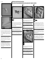
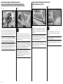
Apply a drop of light machine oil on the axle, then slide
the wheel on the axle. The heads of the screws in the
wheel face away from the fuselage. Secure a wheel collar
by tightening the setscrew on the flat area on the landing
gear axle. The end of the wheel collar will be flush with
the end of the axle.
Geben Sie einen Tropfen Nähmaschinenöl auf die Achse
und setzen dann das Rad auf. Die Schrauben auf der
Radkappe zeigen dabei nach aussen. Sichern Sie den
Stellring mit der Madenschraube auf der flachen Stelle
der Achse. Das Ende des Stellringes schließt bündig mit
der Achse ab.
Applicare sull’asse una goccia di olio leggero. Le
teste delle viti della ruota devono essere rivolte verso
l’esterno. Fissare un collare stringendo il grano sulla
parte piatta dell’asse del carrello. Il collare deve essere
allineato con il terminale dell’asse.
4
L
R
L
R
1/8 inch
x2
M3 x 3
x2
Slide a wheel collar on the axle. Do not tighten the
setscrew at this time.
Schieben Sie einen Stellring auf die Achse. Ziehen Sie die
Madenschraube jetzt noch nicht an.
Inserire un collare sull’asse della ruota. A questo punto
non stringere ancora il grano.
6
L
R
L
R
Slide the inside wheel collar against the wheel, then
secure it by tightening the setscrew.
Schieben Sie den inneren Stellring an das Rad und
sichern ihn mit der Madenschraube.
Far scorrere il collare interno fin contro la ruota, poi
fissarlo stringendo il grano.
7
L
R
L
R
Use a drop or two of canopy glue to keep the hub cap in
position before snapping it into the wheel.
Geben Sie auf die Radkappe ein wenig
Kabinenhaubenkleber bevor Sie diese in das Rad
einklicken.
Usare una goccia o due di colla per capottine per tenere
in posizione il copriruota prima di agganciarlo alla ruota.

19
1
#4
x2
4-40 x 1-inch
x2
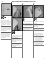
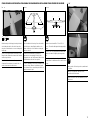
Attach the wing to the fuselage by inserting the dowels
at the leading edge into the holes in the former, then
using the screws and washers to secure the wing at the
trailing edge.
Setzen Sie die Tragfläche mit den Stiften zuerst in den
Rumpf ein und schrauben diese dann mit den Schrauben
und Unterlegscheiben fest.
Fissare l’ala alla fusoliera inserendo le spine sul bordo
di entrata nei fori predisposti, poi, usando le viti e le
rondelle, fissarla anche al bordo di uscita.
2
A A
A=A
Slide the stabilizer in the fuselage. Center the stabilizer
on the fuselage as shown. Align the stabilizer so the
distance from the tips of the stabilizer to the wing tips
match on each side.
Schieben Sie das Höhenruder in den Rumpf ein
und zentrieren es wie abgebildet. Richten Sie das
Höhenruder so aus, dass die Distanz des Ruders zu den
Tragflächenspitzen auf beiden Seiten gleich ist.
Inserire lo stabilizzatore nella fusoliera centrandolo come
si vede nel disegno. Allineare lo stabilizzatore in modo
che la distanza delle sue estremità da quelle dell’ala sia
uguale da entrambe le parti.
3
A A
A=A
Stand back from the model 8 to 10 feet (2.5 to 3
meters). The stabilizer will align with the wing equally as
shown.
Stellen Sie sich 2,5 bis 3 Meter hinter das Modell. Das
Leitwerk sollte mit der Tragfläche gleich ausgerichtet
sein.
Stando dietro al modello ad una distanza di 2,5 - 3m,
bisogna allineare lo stabilizzatore all’ala, come di vede nel
disegno.
4
Mark the outline of the fuselage on the top and bottom of
the stabilizer.
Markieren Sie auf der Ober- und Unterseite die
Aussenlinien des Höhenleitwerks.
Segnare sia sopra che sotto allo stabilizzatore il profilo
della fusoliera.

20
5
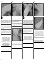
Remove the stabilizer from the fuselage. Use a hobby
knife with a new #11 blade to remove the covering 1/16
inch (1.5mm) INSIDE the lines drawn in the previous
step.
Nehmen Sie das Leitwerk aus dem Rumpf heraus.
Entfernen Sie vorsichtig mit einem Hobbymesser mit 11
Klinge die Folie 1,5mm hinter der Markierung aus dem
vorherigen Schritt.
Togliere lo stabilizzatore dalla fusoliera. Con una lametta
per hobby #11 togliere dallo stabilizzatore il rivestimento
compreso all’INTERNO di 1,5mm delle due linee segnate
prima.
Î We recommend using a soldering iron
or hot knife to remove the covering to reduce
the chances of cutting into the underlying
wood, which will weaken the stabilizer.
Î Wir empfehlen für diesen Schritt
ein Bügeleisen oder heisses Messer zu
verwenden um die Wahrscheinlichkeit das
Holz zu beschädigen zu minimieren
Î Per togliere il rivestimento noi
raccomandiamo l’uso di un saldatore o di una
lama calda per evitare di incidere troppo il
legno e quindi indebolire lo stabilizzatore.
8
Slide the stabilizer back into the fuselage. After checking
the alignment, wick thin CA along the joint between the
stabilizer and fuselage. Apply CA to both the top and
bottom and left and right of the stabilizer/fuselage joint.
Schieben Sie das Leitwerk zurück in den Rumpf. Kleben
Sie nach der Ausrichtung das Leitwerk mit dickflüssigem
Sekundenkleber auf der Ober- und Unterseite ein.
Inserire lo stabilizzatore nella fusoliera. Dopo aver
verificato l’allineamento, far scorrere della colla CA
liquida lungo la linea di unione tra stabilizzatore e
fusoliera, sui lati, sopra e sotto.
Î Do not use CA accelerator during this
step. The CA must be allowed to wick into the
joint between the fuselage and stabilizer.
Î Verwenden Sie bei diesem Arbeitsschritt kein
Aktivator. Der Sekundenkleber muß in den Spalt
zwischen Leitwerk und Rumpf eindringen können.
Î Non usare acceleranti CA durante
questa fase. La colla CA potrebbe penetrare
nel giunto tra fusoliera e stabilizzatore.
9
Use a pin vise and 1/16-inch (1.5mm) drill bit to drill a
hole in the center of each hinge slot. Prepare both the
elevator and stabilizer at this time. Place a T-pin in the
center of each of the elevator hinges. Fit the hinges in
the elevator, resting the T-pin on the leading edge of the
elevator.
Bohren Sie mit dem Handbohrer ein Loch in die Mitte
von jedem Scharnierschlitzes. Bereiten Sie beide
Ruderblätter vor. Stecken Sie eine T-Nadel in die Mitte
der Scharniere und diese dann in die Ruderblätter.
Usare una punta da 1,5mm per forare al centro di ogni
fessura prevista per le cerniere. Mettere uno spillo a
T al centro di ogni cerniera per l’elevatore. Inserire le
cerniere facendo in modo che gli spilli si appoggino al
bordo di entrata dell’elevatore.
6
Use sandpaper to lightly sand the elevator joiner wire
where it will fit into the elevators.
Schleifen Sie mit Sandpapier den Leitwerksbügel der in
die Höhenruderhälften gesteckt wird an.
Usare della carta vetrata per carteggiare la barretta di
acciaio che unisce le due parti dell’elevatore, per la parte
che entra nel legno.
7
Slide the joiner wire into the slot for the stabilizer.
Schieben Sie den Ruderverbinder in den Leitwerksschlitz.
Inserire la suddetta barretta di unione, nella fessura
prevista per lo stabilizzatore.

21
10
L
R
L
R
Fit the elevator to the stabilizer using the hinges. Make
sure the joiner wire also fits into the elevator.
Richten Sie die Ruderblätter aus. Bitte achten Sie darauf
das der Ruderverbinder ebenfall in die Ruder paßt.
Unire lo stabilizzatore all’elevatore usando le cerniere.
Verificare che la barretta di unione entri nell’elevatore.
Î Make sure the elevator with the slot for the
control horn is on the correct side of the fuselage.
Î Bitte achten Sie darauf, dass der Schlitz
für das Ruderhorn auf der richtigen Seite ist.
Î Verificare che l’elevatore con la sede per la
squadretta sia dalla parte giusta della fusoliera.
12
L
R
L
R
Align the tip of the elevator with the tip of the stabilizer.
Apply thin CA to the top and bottom of each hinge. Once
the CA cures, gently pull on the fixed surface and control
surface to make sure the hinges are glued securely. If
not, apply additional CA to secure each of the hinges.
Richten Sie die Enden des Ruders passend zu den
Enden des Leitwerks aus. Geben Sie auf die Ober- und
Unterseite der Scharniere dünnflüssigen Sekundenkleber.
Ziehen Sie nach aushärten des Kleber vorsichtig an den
Ruderblättern um die Klebung zu überprüfen. Kleben Sie
falls notwendig nach.
Allineare bene tra di loro le estremità di elevatore e
stabilizzatore e poi mettere un po’ di colla CA liquida sia
sopra che sotto alle cerniere. Quando la colla è asciutta,
tirare leggermente cercando di allontanare l’elevatore
dallo stabilizzatore per accertarsi che le cerniere siano
incollate bene. Se non fosse così mettere dell’altra colla
CA sulle cerniere facendo attenzione però che non vada
sui loro perni.
11
L
R
L
R
5
Remove the elevator from the stabilizer. Apply a small
amount of epoxy on the joiner and elevator where they
contact each other. Place the elevator back into position,
fitting the elevator tightly against the stabilizer.
Nehmen Sie das Höhenruderblatt wieder vom Ruder.
Geben Sie etwas Epoxy auf die Kontaktstellen von
Verbinder und Ruderblatt. Setzen Sie das Ruder wieder
ein und achten auf eine gute Passung.
Togliere l’elevatore dallo stabilizzatore. Mettere una
piccola quantità di colla epoxy sulla barretta di unione e
nella sua sede sull’elevatore. Mettere l’elevatore di nuovo
in posizione, unendolo bene allo stabilizzatore.
INSTALLAZIONE DEL TIMONE
1
OIL
Apply a small amount of petroleum jelly to the tail gear
wire near the bushing. Slide the bushing up and down on
the wire to work the petroleum jelly into the bushing to
help prevent adhesives from gluing the bushing to the
wire.
Geben Sie über über- und unterhalb des Lagers etwas
Vaseline auf den Draht. Schieben Sie das Lager rauf und
runter um die Vaseline darunter zu verteilen. Dieses
verhindert dass Sie das Lager am Spornraddraht
festkleben.
Mettere un po’ di vaselina sulla gamba del carrello di
coda vicino alla bussola. Far scorrere la bussola su e giù
per distribuire bene la vaselina al suo interno ed evitare
che entri della colla e la blocchi sulla gamba.

22
2
Use sandpaper to lightly sand the tail wheel wire where
it will be inserted into the rudder.
Rauen Sie das waagerechte Ende des Spornraddraht an,
dass in das Ruder gesteckt wird.
Usare carta vetrata per carteggiare leggermente la
parte della gamba del carrello di coda che entra nel
timone.
3
5
Use a small amount of epoxy to glue the bushing into
the fuselage. Slide the bushing down so it is positioned
at the bottom of the pre-cut slot at the rear of the
fuselage.
Kleben Sie mit etwas Epoxy das Lager in den Rumpf.
Richten Sie das Spornrad so aus, dass das Lager am
unteren Ende des Schlitzes ist.
Usare un po’ di colla epoxy per incollare la bussola alla
fusoliera. Portare la bussola verso il basso della fessura
sulla fusoliera.
4
Use a pin vise and 1/16-inch (1.5mm) drill bit to drill a
hole in the center of each hinge slot. Prepare both the
rudder and fin at this time. Place a T-pin in the center of
each of the rudder hinges. Fit the hinges in the rudder,
resting the T-pin on the leading edge of the rudder.
Bohren Sie mit dem Handbohrer ein Loch in die Mitte von
jedem Scharnierschlitzes. Bereiten Sie beide Ruder vor.
Stecken Sie eine T-Nadel in die Mitte der Scharniere und
diese dann in die Ruderblätter.
Usare una punta da 1,5mm per forare al centro di ogni
fessura prevista per le cerniere. Preparare sia il timone
che il direzionale. Mettere uno spillo a T al centro di ogni
cerniera per il timone. Inserire le cerniere facendo in
modo che gli spilli si appoggino al bordo di entrata del
timone.
5
Fit the rudder to the fin using the hinges. Make sure the
tail wheel wire also fits into the rudder. Trim the slot in
the rudder as necessary to fit over the tail gear bushing.
Passen Sie das Ruder an der Finne an und achten bitte
darauf, dass sich der Spornradhalter im Ruder befindet.
Passen Sie falls notwendig den Schlitz des Ruders an.
Unire il timone al direzionale usando le cerniere.
Verificare che anche la gamba del carrello di coda sia
inserita nel timone. Regolare la fessura nel timone per
arrivare sopra alla bussola del carrello di coda.
6
5
Remove the rudder from the fuselage. Apply a small
amount of epoxy on the tail gear wire and rudder where
they contact each other. Place the rudder back into
position, fitting the rudder tightly against the fin.
Nehmen Sie das Seitenruderblatt vom Rumpf ab. Geben
Sie etwas Epoxy auf die Kontaktstellen von Ruderblatt
und Spornraddraht. Setzen Sie das Ruderblatt wieder ein
und achten auf eine gute Passung.
Togliere il timone dalla fusoliera. Mettere un po’ di colla
epoxy sulla gamba del carrello di coda e sul timone nel
punto in cui entrano in contatto. Rimettere in posizione il
timone e unirlo strettamente al direzionale.

23
7
Once the epoxy fully cures, apply thin CA to both sides of
each hinge. Once the CA cures, gently pull on the fixed
surface and control surface to make sure the hinges are
glued securely. If not, apply additional CA to secure each
of the hinges.
Geben Sie auf die Ober- und Unterseite der Scharniere
dünnflüssigen Sekundenkleber. Ziehen Sie nach aushärten
des Kleber vorsichtig am Ruderblatt um die Klebung zu
überprüfen. Kleben Sie falls notwendig nach.
Quando la colla epoxy è completamente asciutta,
mettere della colla CA liquida su entrambi i lati delle
cerniere. Quando la colla è asciutta, tirare leggermente
cercando di allontanare il timone dal direzionale per
accertarsi che le cerniere siano incollate bene. Se non
fosse così mettere dell’altra colla CA sulle cerniere
facendo attenzione però che non vada sui loro perni.
1
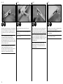
Insert the 17
11
/
16
-inch (450mm) pushrod into the center
hole of the control horn. This will be used for the elevator
control wire.
Stecken Sie das 450mm lange Höhenrudergestänge in
die Mitte des Ruderhorns.
Inserire la barretta di comando (450mm) nel foro
centrale della squadretta. Questa si userà per
l’elevatore.
2
Guide the pushrod wire into the tube installed in the
fuselage. Insert the control horn in the slot from the
bottom of the stabilizer.
Führen Sie das Gestänge in das Röhrchen im Rumpf und
stecken das Ruderhorn in den Schlitz auf der Unterseite
des Ruders.
Inserire la barretta di comando nel tubo installato in
fusoliera. Sistemare la squadretta nella sua fessura
passando dal retro della fusoliera.
3
Snap the control horn backplate on the top of the control
horn. The horn and backplate must be tight against the
surface of the stabilizer. Apply a few drops of CA on the
backplate to fully secure it to the control horn.
Setzen Sie die Rückplatte auf der anderen Seite des
Ruders auf das Ruderhorn auf und achten auf einen
festen Sitz. Die Platte muß fest auf der Ruderfläche
aufliegen. Verkleben Sie diese mit ein paar Tropfen
Sekundenkeber.
Agganciare la piastrina sulla squadretta; entrambe
devono aderire bene alla superficie dell’elevatore.
Mettere alcune gocce di colla CA sulla piastrina per
fissarla completamente alla squadretta.

24
4
The rudder control horn follows the same procedure as
the elevator control horn. Make sure the Z-bend of the
18
1
/
8
-inch (460mm) pushrod is inserted in the outer hole
of the control horn before securing the control horn in
the rudder.
Montieren Sie das Seitenruderhorn und Gestänge
auf gleiche Weise. Bitte achten Sie darauf, dass
das 460mm lange Gestänge in das äußere Loch des
Ruderhorns gesteckt wird bevor Sie das Ruderhorn im
Seitenruder verkleben.
Per la squadretta del timone si segue la stessa
procedura usata per l’elevatore. Accertarsi che la
barretta di comando con estremità a Z (460mm) sia
inserita nel foro più esterno della squadretta prima di
fissarla al timone.
2
Thread a servo mounting screw into each of the holes for
mounting the rudder and elevator servos.
Drehen Sie eine Servobefestigungsschraube in jedes
Loch der Seiten- und Höhenruderservobefestigung
Avvitare un vite per il montaggio dei servi in ciascun foro
del supporto.
3
Apply a small amount of thin CA to harden the threads
made in the previous step.
Geben Sie einen kleinen Tropfen dünnflüssigen
Sekundenkleber in die Gewindelöcher um diese zu härten.
Mettere una piccola quantità di colla CA nei fori, per
indurire il filetto fatto nel passaggio precedente.
1
x2
Use the radio system to center the rudder and elevator
servos. Attach the brass pushrod connector in the hole
in the servo arm that is 7/16 inch (11mm) from the
center of the servo arm.
Zentrieren Sie mit der Fernsteuerung beide Servos.
Setzen Sie den Gestängeanschluss in das Loch des
Servoarms der 11mm von der Mitte entfernt ist.
Usare il radiocomando per centrare i servi di timone ed
elevatore. Attaccare il nottolino di ottone nel foro della
squadretta del servo che dista 11mm dal centro.
4
M2 x 6
x2
Secure the rudder and elevator servos in the fuselage.
Insert the pushrod wires through the connectors on the
servo arms. Use the radio system to center the servos.
Once the elevator and rudder are centered, the pushrod
wires can be secured in the connectors using the screws
listed.
Bauen Sie die Servos wie abgebildet ein. Führen Sie die
Gestänge in die Gestängeanschlüsse und zentrieren die
Servos mit der Fernsteuerung. Schrauben Sie danach die
Gestängeanschlüsse fest.
Fissare in fusoliera i servi di elevatore e timone. Inserire
le barrette di comando nei nottolini di connessione
posti sulle squadrette dei servi.. Usare il radiocomando
per centrare i servi. Quando elevatore e timone sono
centrati, fissare le barrette di comando con le loro viti.

25
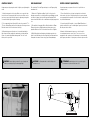
1
Attach the X-mount to the motor using the hardware
provided with the motor.
Montieren Sie den X-Träger mit dem mitgelieferten
Schrauben am Träger.
Collegare il supporto a X al motore, usando la viteria
fornita con esso.
3
Place the leads of the motor inside the fuselage so they
don’t interfere with mounting the cowling.
Führen Sie die Motorkabel in den Rumpf, so dass sie die
Montage der Motorhaube nicht behindern.
Far entrare in fusoliera i fili del motore in modo che non
possano interferire con il montaggio della capottina.
PREPARAZIONE DELLA CAPOTTINA
MOTORE
1
x2
Cut a piece of card stock and tape it to the fuselage to
indicate the edge of the fuselage.
Schneiden Sie ein Stück Karton aus um das Rumpfende
zu markieren.
Tagliare un pezzo di cartoncino e fissarlo con nastro alla
fusoliera per indicarne il bordo.
2
Secure the motor to the motor box using the hardware
provided with the motor.
Schrauben Sie den Motor mit dem X-Träger mit den
mitgelieferten Schrauben an der Motorbox fest.
Fissare il motore alla scatola di supporto usando le viti
fornite con il motore.
La pagina si sta caricando...
La pagina si sta caricando...
La pagina si sta caricando...
La pagina si sta caricando...
La pagina si sta caricando...
La pagina si sta caricando...
La pagina si sta caricando...
La pagina si sta caricando...
La pagina si sta caricando...
La pagina si sta caricando...
La pagina si sta caricando...
La pagina si sta caricando...
La pagina si sta caricando...
La pagina si sta caricando...
La pagina si sta caricando...
-
 1
1
-
 2
2
-
 3
3
-
 4
4
-
 5
5
-
 6
6
-
 7
7
-
 8
8
-
 9
9
-
 10
10
-
 11
11
-
 12
12
-
 13
13
-
 14
14
-
 15
15
-
 16
16
-
 17
17
-
 18
18
-
 19
19
-
 20
20
-
 21
21
-
 22
22
-
 23
23
-
 24
24
-
 25
25
-
 26
26
-
 27
27
-
 28
28
-
 29
29
-
 30
30
-
 31
31
-
 32
32
-
 33
33
-
 34
34
-
 35
35
-
 36
36
-
 37
37
-
 38
38
-
 39
39
-
 40
40


E-flite J-3 Cub 450 Manuale utente
- Categoria
- Giocattoli telecomandati
- Tipo
- Manuale utente
in altre lingue
- English: E-flite J-3 Cub 450 User manual
- Deutsch: E-flite J-3 Cub 450 Benutzerhandbuch
Documenti correlati
-
E-flite Extra 330SC BP Manuale utente
-
E-flite Mystique EFL4905 Manuale utente
-
arf EFL2790 Manuale del proprietario
-
-
E-flite Beast 60e Manuale utente
-
-
E-flite Carbon-Z Cub Manuale utente
-
-
Altri documenti
-
Horizon Hobby Mystique RES 2.9m ARF Manuale utente
-
 KYAZHO EDGE 540 Manuale utente
-
Evolution EVOE10GX Manuale utente
-
Hangar 9 HAN5015 Manuale del proprietario
-
 Hangar 9 HAN2345 Manuale del proprietario
-
 Hangar 9 HANGAR 9 Ultra Stick 30cc Manuale del proprietario
-
 Hangar 9 HAN5080 Manuale del proprietario
-
 HYPE 018-1560 Manuale utente
-
Kyosho EP JET F-22 RAPTOR DF55 PIP(No.10284) Manuale utente
-
FMD Furniture Variant 7 205-007 Assembly Instructions


