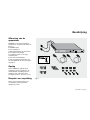
Eaton STS 16 Installation and User Manual
- Categoria
- Gruppi di continuità (UPS)
- Tipo
- Installation and User Manual

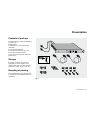
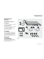
Installation and user
manual
STS
Source Transfer
Switch
www.eaton.com
English
Français
Deutsch
Italiano
Español
Nederlands

5102761700/AI
English .......................... 1
Français ....................... 15
Deutsch ........................ 29
Italiano ......................... 43
Español ........................ 57
Nederlands .................. 71

51027617EN/AI - Page 1
Contents
All EATON products are protected by patents. They implement original technology which is not available to other
competitors of EATON.
To take evolving standards and technology into account, the technical characteristics contained in this document are
not binding unless confirmed by EATON.
This document may be reproduced only with the consent of EATON. Authorised copies must be marked "EATON STS
installation and user manual nr 5102761700".
Warning .................................................................................................................2
Presentation
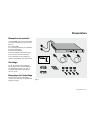
Contents of package ......................................................................................3
Storage ...........................................................................................................3
Recycling of packing ......................................................................................3
Function .........................................................................................................4
Characteristics ..............................................................................................4
Overall views .................................................................................................5
Installation
Setting the input voltage ................................................................................7
Installation ......................................................................................................8
Connections ..................................................................................................9
Communication ............................................................................................10
Operation ...........................................................................................................12
Troubleshooting ..............................................................................................13
Appendices
Glossary .......................................................................................................14
Index ............................................................................................................14

Page 2 - 51027617EN/AI
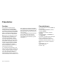
Warning
Thank you for selecting an EATON
product to protect your equipment.
You have chosen a STS to ensure the
high availability of your IT systems,
i-e more than 1500 transferts between
the preferred source and the alternate
source.
This STS benefits from a 2 year warranty.
This warranty is valid if you comply with
the following specifications (*) :
Only the computational load can be z
connected to the STS, all the others
types of loads (resistive, inductive or
crest factor >3:1 ) are not covered by the
warranty
The length of the cable between the
z
source (UPS or transformer) and the
STS must be at minimum 50 m, with a
maximum cross-section of 6 mm².
For that reason the Canalis busbar
type does not comply with the STS
specifications.
The 2 sources must be synchronized
z
and you should prevent the phase/neutral
inversion. A desynchronisation (signaled
by the "Site wiring fault" indication LED)
betweeen the two phases of the sources
is a cause of premature ageing of the
STS components.
(*) Don't concern sources and UPS below
6 KVA.

51027617EN/AI - Page 3
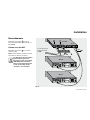
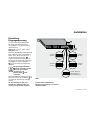
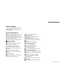
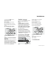
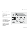
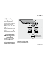
Contents of package
The STS package contains the following
(see figure 1):
STS module, z
installation and user manual (this z
document),
four adhesive footpads,
z
four M6 bolts with four cage nuts, z
two communications cables, z
two securing systems for equipment z
power cords.
Storage
If the STS module is stored prior to
installation, it should remain in the
original packing in a dry place (storage
temperature range: -40 °C to +70 °C).
Recycling of packing
Packing materials must be disposed of
in compliance with applicable laws and
regulations.
Presentation
Fig. 1
www.eaton.com

Page 4 - 51027617EN/AI
Function
EATON developed STS to guarantee the
uninterrupted operation of your sensitive
equipment. The STS source transfer
switch is a simple and effective solution
to manage the redundancy provided by
two independent power sources.
STS handles the automatic or manual
transfer of your loads between two
independent power sources without
interrupting the supply of power (< 6
milliseconds). Either of the two sources
may be designated as the preferred
source with the other becoming the
alternate source. In the event of a
failure, transfer from one to the other is
automatic and instantaneous.
Automatic transfer to the alternate
source takes place if the voltage of the
preferred source goes outside a tolerance
of 12 % above or below the nominal
value. Return to the preferred source
is automatic when the voltage returns
within the ±12 % tolerance range.
To provide a maximum level of
protection for the connected sensitive
equipment, both power sources should
be on-line type UPSs. However, the STS
module can also be supplied by one UPS
and another type of source, or by two
non-UPS sources providing a sinusoidal
output (AC system, engine generator set,
etc.).
Presentation
Characteristics
The STS module has the following
characteristics:
208 / 220 / 230 / 240 V versions (input z
voltage): STS 16,
120 V version (input voltage):
z
STS 1400,
input current: 16 A (
z STS 16), 12 A (STS
1400),
protection by thermal circuit breakers
z
(16 A or 12 A depending on the version),
threshold before transfer from
z
preferred to alternate source: ±12 %,
maximum operating temperature:
z
35 °C,
dimensions: 1U x 19 inches (44.45 mm
z
x 482.6 mm);
weight: 5 kg.
z

51027617EN/AI - Page 5
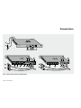
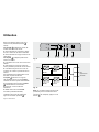
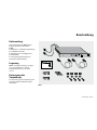
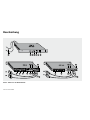
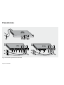
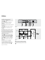
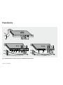
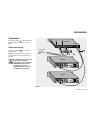
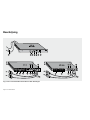
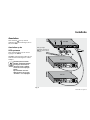
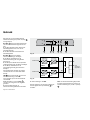
Overall views
Figure 2 shows in detail the front and
rear panels of the various STS versions.
Key to figure 2:
1
voltage indication LEDs for the two
power sources S1 and S2:
green LED: voltage OK, within tolerances,
red LED: voltage NOK, outside ±12 %
tolerances,
2
button used to select the preferred
source:
: source S1 is the preferred source,
: source S2 is the preferred source,
3
status LEDs for the source currently
supplying power:
OFF: source not used.
green: preferred source supplying power,
yellow: alternate source supplying
power,
Note: only one of these LEDs is ON at a
time,
4
red LED indicating a STS fault,
5
buzzer OFF pushbutton,
6
buzzer,
7
connection cables between the
module and the two power sources S1
and S2,
8
connection sockets for the sensitive
equipment.
STS 16
z : 6 IEC-type sockets 10 A and 1
IEC-type socket 16 A,
STS 1400
z : 6 NEMA-type sockets,
9
output protection circuit breakers on
STS 16,
10
SUB-D 9-pin connector, for
communication (UPS S1 type) from
source 1,
11
SUB-D 9-pin connector, for
communication (UPS S2 type) from
source 2,
12
SUB-D 9-pin connector, for outgoing
communication (Basic type),
13
SUB-D 9-pin connector, for outgoing
communication (STS COM type, i.e. dry
contacts),
14
STS input voltage selector (European
versions),
15
protection circuit breakers on the
inputs from the two sources,
16
"sources out of synchronisation"
indication LED.
Presentation

Page 6 - 51027617EN/AI
Fig. 2 : front and rear panels of the STS modules
Presentation

51027617EN/AI - Page 7
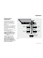
Installation
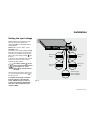
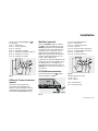
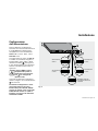
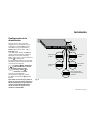
Setting the input voltage
Before making any connections, make
sure that the sources selected to
supply the STS are compatible with its
characteristics.
STS 16: 208 V - 220 V - 230 V - 240 V.
STS 1400: 120 V.
The factory input voltage setting for STS
16 is 230 V. If necessary, set the voltage
to another value (208 V, 220 V, 230 V or
240 V) using the voltage selector
14
(see
figure 3).
In the event of an electrical fault, a circuit
breaker on each of the source inputs
protects the STS module.
The voltage selector
14
may be
used only when the STS module
is de-energized, i.e. power
cables
7
not connected to the
sources.
Once the module has been correctly set
up, connect the two power cables
7
to
the two sources.
To facilitate the upstream connection
from the STS 16 to a FR or Schuko
socket, EATON provides, as option, a
2 power cable kit IEC C 19/FR-Schuko
male inlet, 1,90 m length whose part
number is 66397.
Fig. 3
230 V input
voltage
240 V input
voltage
208 V input
voltage
220 V input
voltage
Enhanced mode
for line interactive
UPS compatibility

Page 8 - 51027617EN/AI
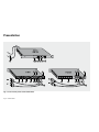
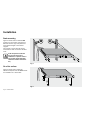
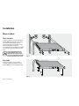
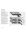
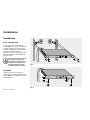
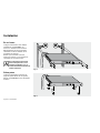
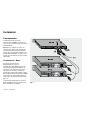
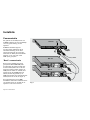
Installation
On a flat surface
Figure 5 shows how to attach the
adhesive footpads under the STS module
for installation on a flat surface.
Fig. 5
Fig. 4
Rack mounting
Figure 4 shows how to install the STS
module in a 19-inch bay using the four
M6 bolts and the cage nuts positioned
at the desired height in the cabinet
uprights.
The module is not as wide as the bay
and therefore does not obstruct the flow
of air.
If the temperature inside the
bay can rise above 35 °C,
ventilation is required. If this is
not possible, the STS module
should be installed outside the
bay.

51027617EN/AI - Page 9
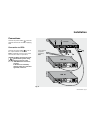
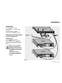
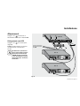
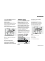
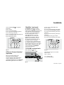
Connections
Connect the power cables
7
to the two
electrical sources (S1 and S2) supplying
STS.
Connection to UPSs
Connect the power cables
7
to one of
the output sockets on each UPS.
STS is energized as soon as one of the
sources (S1 or S2) is in operation.
The UPSs must have the same
characteristics (power rating,
autonomy) and be of the
"ON-LINE double conversion"
topology.
In the event of redundancy
achieved using two "Evolution"
type UPSs, consult us.
Fig. 6
Installation
STS 16A
8
Ba
sic
T
6.3
A
25
0V
~
U
e
/I
n/E
in
g
A
mp
: 2
5A
Vo
lt: 38
Vd
c
I m
a
x 4
.3
A
Us
/O
ut/
Au
sg
Ba
s
ic
T
6.
3A
2
50
V
~
U
e/In/E
in
g
A
mp
: 2
5A
Vo
lt:
38
Vd
c
I m
a
x 4
.3A
Us
/O
ut/Au
sg
8
S2
S1
7
UPS S2
UPS S1
to the sensitive
equipment
supplied by
STS

Page 10 - 51027617EN/AI
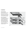
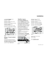
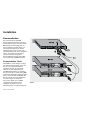
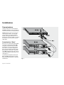
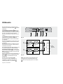
Communication
Use of the communications ports on the
STS module is optional and not required
for correct operation of the module.
STS is equipped as standard with a Basic
communications port for incoming data
from both sources S1 and S2 (both UPSs
must have a free Basic port), as well as
with an STS COM communications port.
Basic communication
For a High Availability Pack configuration,
the Basic STS communications port
receives the data from both UPS sources
S1 and S2. To activate the port, it is
necessary to connect the UPS S1 and
UPS S2 communications ports on the
module to the Basic communications
ports on the UPSs S1 and S2, using the
cables supplied with STS (see figure 7).
The Basic port of the STS always
forwards the status information provided
by the Basic port of the UPS currently
supplying the equipment.
Fig. 7
Installation

51027617EN/AI - Page 11
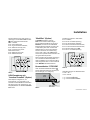
Fig. 8
The pin-out of the Basic STS port
12
is
the following:
pin 1 – frame earth,
z
pin 4 – normal operation, z
pin 5 – common, z
pin 6 – operation on bypass, z
pin 7 – low battery shutdown warning, z
pin 8 – operation on inverter, z
pin 9 – operation on battery. z
Fig. 10
Fig. 9
UPS with "Protocol Interface"
(option)
This option converts Basic type
information into the RS232 serial
protocol. It is then possible to use the
administration and system shutdown
capabilities of Solution Pac software.
Breaking capacity of relays:
V max = 30 V
I max = 100 mA
NO = normally open,
NC = normally closed.
MultiSlot (optional)
When the MultiSlot option is installed,
the STS and the two UPSs act as a one.
MultiSlot, equipped with two MetaUPS
acquisition cards, concentrates the data
coming from the U-Talk ports on the
UPSs and from the STS COM port on
STS. Communication with the protected
systems is optimized through use of a
U-Talk, J-Bus or SNMP card.
In this case, the protected application will
shutdown only when all available energy
has disappeared, i.e. the batteries on
both UPSs have been depleted. See the
MultiSlot user manual for information on
connections.
STS COM communication
This communications port
13
supplies
status information on STS.
Pin-out of the STS COM port:
pin 1 – frame earth,
z
pin 4 – source S2 preferred, z
pin 5 – common, z
pin 6 – source S1 within tolerances, z
pin 7 – source S2 within tolerances, z
pin 8 – no fault in STS, z
pin 9 – source S1 preferred. z
Installation

Page 12 - 51027617EN/AI
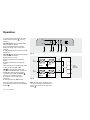
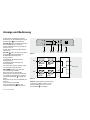
Operation
1
S1
S2
2 3 4 5 6
It is assumed here that source S1 is the
preferred source (button
2
in the up
position).
The LEDs
1
indicate the voltage status
of the sources S1 and S2.
green indicates that the voltage is
z
within tolerances (±12 % of the rated
voltage).
red indicates that the voltage is outside
z
tolerances.
The LEDs
3
indicate the operating status
of the sources S1 and S2.
OFF: source not used.
z
green: preferred source supplying z
power.
yellow: alternate source supplying
z
power.
The applications are supplied with power
if either of the two LEDs is ON.
LED
4
is red if an internal fault has
occurred in the STS module. Contact the
EATON after-sales technical support.
In addition to the LEDs, the buzzer
6
sounds in the following events:
source S1 or source S2 outside
z
tolerances;
internal fault in the
z STS module.
Once the problem has been identified,
the buzzer may be turned off by pressing
button
5
.
Fig. 11
Fig. 12
AC
source
rectifier
battery
inverter
to the
sensitive
equipment
AC
source
rectifier
battery
inverter
UPS S1
UPS S2
STS
S1
S2
Note: to make source S2 the priority
source (for example, if maintenance is
required on source S1), simply press
button
2
.

51027617EN/AI - Page 13
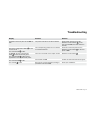
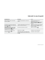
Troubleshooting
Display Problem Solution
All LEDs on the front panel of the STS are
OFF.
The power sources S1 and S2 are absent. Check power sources S1 and S2.
Reset the circuit breakers
15
on the
rear panel of STS (if the fault has been
cleared).
One of the voltage-status LEDs
1
for the
sources is red.
The red fault LED
4
is OFF.
The corresponding power source is absent
or outside tolerances.
Check the concerned power source.
Reset the circuit breaker
15
on the rear
panel of STS.
On STS 16, the two voltage-status
LEDs
1
for the sources are green.
The red fault LED
4
is OFF and the
application is not supplied with power.
There is an overload on the output circuits.
Reset the circuit breaker
9
.
The red fault LED
4
is ON.
Internal fault in STS. Contact the after-sales technical support.
The red LED
16
is ON.
Sources out of synchronization, leading to
premature wear of the STS.
Check your installation.

Page 14 - 51027617EN/AI
Appendices
Index
Adhesive footpads: .................................................................................................8
Bay (installation): .......................................................................................................8
Buzzer (operation and reset): ..............................................................................5, 12
Circuit breakers (reset): .....................................................................................5, 13
Communications pin-outs: ...................................................................................11
Contents of module: ...............................................................................................3
Input voltage sel ector: .......................................................................................5, 7
LEDs (meaning): ..................................................................................................5, 12
Packing: ....................................................................................................................3
Power supply (characteristics): ................................................................................4
Selection of preferred source: ..........................................................................5, 12
UPS: ......................................................................................................................4, 9
Warnings (
): ..................................................................................................2, 7-8
Glossary
Alternate source: power source S1 or S2
for STS module, selected as alternate
using button
2
Basic: data exchange protocol for status
information on sources S1 and S2
Operation on bypass: source S1 or S2
supplying power directly from their AC
source
Operation on inverter: source S1 or S2
supplying protected, quality power via
their inverter
Preferred source: power source S1 or S2
for STS module, selected as preferred
using button
2
Selector: set of eight DIP switches used
to select the input voltage for the STS
module
Sensitive equipment: devices supplied
and protected by the STS module
STS COM: data exchange protocol for
status information on the STS module,
via dry contacts
SUB-D 9-pin connector: connector with
nine pins, used for communications
signals
UPS: uninterruptible power supply.

51027617FR/AI - Page 15
Avertissement ...............................................................................................16
Présentation
Réception du matériel .................................................................................17
Stockage ......................................................................................................17
Recyclage .....................................................................................................17
Fonction ......................................................................................................18
Caractéristiques ..........................................................................................18
Vues d’ensemble .........................................................................................19
Installation
Configuration de l'alimentation ....................................................................21
Mise en place .............................................................................................22
Raccordements ...........................................................................................23
Communication ............................................................................................24
Utilisation .........................................................................................................25
Dépannage .......................................................................................................27
Annexes
Glossaire ......................................................................................................28
Index ............................................................................................................28
Sommaire
Tous les produits de la gamme EATON sont protégés par des brevets ; ils mettent en œuvre une technologie originale
qui ne pourra être utilisée par aucun concurrent de EATON.
En raison de l’évolution des normes et du matériel, les caractéristiques indiquées dans ce document ne nous engagent
qu’après conrmation par nos services.
Reproduction de ce document autorisée après accord de EATON et avec la mention obligatoire :
"Manuel d'installation et d'utilisation du module STS de EATON n° 5102761700".

Page 16 - 51027617FR/AI
Avertissement
EATON vous remercie de votre
confiance. Vous avez choisi STS pour
assurer la haute disponibilité de vos
équipements informatiques, soit plus de
1500 manœuvres entre source prioritaire
et source de réserve.
La garantie légale sur cet appareil est
de 2 ans. Elle ne couvre que les cas
d'utilisation respectant les préconisations
suivantes (*) :
Seules les charges informatiques z
peuvent être protégées par la gamme
STS, tout autre type de charge (résistive,
inductive ou à facteur de crête >3:1 )
étant à exclure.
La distance minimale entre la source
z
(Alimentation Sans Interruption ou
transformateur) et STS doit être au
minimum de 50 m, avec une section
maximale de 6 mm
2
.
Les circuits de type Canalis sont à
exclure.
Les 2 sources d'alimentation doivent
z
être en phase (attention à l'inversion
Phase/Neutre) : une désynchronisation
(signalée par le voyant "Site wiring fault")
ou un écart de phase entre les 2 sources
est un facteur d'usure prématurée des
éléments de transfert.
(*) ne s'applique pas aux sources et
onduleurs inférieurs à 6 KVA.

51027617FR/AI - Page 17
Réception du matériel
Le produit STS que vous venez d’acheter
se compose des éléments suivants (voir
figure 1) :
le module STS,
z
un manuel d’installation et d’utilisation z
(le présent document),
quatre pieds adhésifs,
z
quatre vis M6 et quatre écrous-cage, z
deux cordons de communication, z
deux systèmes de verrouillage des z
cordons d'alimentation des équipements.
Stockage
En cas de stockage avant sa mise en
service, laisser votre module STS dans
son emballage d’origine et à l’abri de
l’humidité (température de stockage :
-40 °C à +70 °C).
Recyclage de l'emballage
Concernant le rebut de l'emballage,
veuillez vous conformer aux dispositions
légales en vigueur.
Présentation
Fig. 1
www.eaton.com

Page 18 - 51027617FR/AI
Fonction
Pour garantir le fonctionnement
ininterrompu de vos équipements
sensibles, EATON a développé STS.
Le système de transfert de source STS
offre une réponse simple et efficace en
gérant la redondance d'alimentation à
partir de deux sources indépendantes.
STS permet un transfert sans coupure
(< 6 milisecondes), automatique ou
commandé manuellement, depuis
une source d'alimentation principale
(dite aussi prioritaire) vers une source
d'alimentation secondaire (dite source
de réserve). Vous êtes libre de choisir
la source désignée comme prioritaire,
l'autre source devenant "réserve".
En cas de défaillance, le transfert est
automatique et instantané.
Il y a basculement automatique sur la
source de réserve lorsque la tension de
la source prioritaire s'écarte de plus de
12 % de la valeur nominale. Le retour
sur la source prioritaire s'effectue
automatiquement lorsque cette tension
revient à l'intérieur de la tolérance ±12 %.
Caractéristiques
Les caractéristiques du module STS sont
les suivantes :
versions 208/220/230/240 V (tension z
d'entrée) : STS 16,
version 120 V (tension d'entrée) :
z
STS 1400,
courant d'entrée : 16 A (
z STS 16), ou
12 A (STS 1400),
protection par disjoncteurs thermiques
z
16 A ou 12 A selon les versions,
seuil de basculement entre source
z
prioritaire et source de réserve : ±12 %,
température maximale d'utilisation :
z
35°C,
dimensions : 1U x 19"
z
(44,45 x 482,6 mm),
poids : 5 kg.
z
Pour garantir une protection maximale
des équipements sensibles raccordés, les
deux sources seront de préférence deux
ASI (Alimentation Sans Interruptions) de
type "on line".
Le module STS peut aussi être alimenté
par une ASI et une autre source ou
par deux autres sources alternatives
sinusoÎdales (réseau électrique, groupe
électrogène, ...).
Présentation
La pagina si sta caricando...
La pagina si sta caricando...
La pagina si sta caricando...
La pagina si sta caricando...
La pagina si sta caricando...
La pagina si sta caricando...
La pagina si sta caricando...
La pagina si sta caricando...
La pagina si sta caricando...
La pagina si sta caricando...
La pagina si sta caricando...
La pagina si sta caricando...
La pagina si sta caricando...
La pagina si sta caricando...
La pagina si sta caricando...
La pagina si sta caricando...
La pagina si sta caricando...
La pagina si sta caricando...
La pagina si sta caricando...
La pagina si sta caricando...
La pagina si sta caricando...
La pagina si sta caricando...
La pagina si sta caricando...
La pagina si sta caricando...
La pagina si sta caricando...
La pagina si sta caricando...
La pagina si sta caricando...
La pagina si sta caricando...
La pagina si sta caricando...
La pagina si sta caricando...
La pagina si sta caricando...
La pagina si sta caricando...
La pagina si sta caricando...
La pagina si sta caricando...
La pagina si sta caricando...
La pagina si sta caricando...
La pagina si sta caricando...
La pagina si sta caricando...
La pagina si sta caricando...
La pagina si sta caricando...
La pagina si sta caricando...
La pagina si sta caricando...
La pagina si sta caricando...
La pagina si sta caricando...
La pagina si sta caricando...
La pagina si sta caricando...
La pagina si sta caricando...
La pagina si sta caricando...
La pagina si sta caricando...
La pagina si sta caricando...
La pagina si sta caricando...
La pagina si sta caricando...
La pagina si sta caricando...
La pagina si sta caricando...
La pagina si sta caricando...
La pagina si sta caricando...
La pagina si sta caricando...
La pagina si sta caricando...
La pagina si sta caricando...
La pagina si sta caricando...
La pagina si sta caricando...
La pagina si sta caricando...
La pagina si sta caricando...
La pagina si sta caricando...
La pagina si sta caricando...
La pagina si sta caricando...
La pagina si sta caricando...
La pagina si sta caricando...
-
 1
1
-
 2
2
-
 3
3
-
 4
4
-
 5
5
-
 6
6
-
 7
7
-
 8
8
-
 9
9
-
 10
10
-
 11
11
-
 12
12
-
 13
13
-
 14
14
-
 15
15
-
 16
16
-
 17
17
-
 18
18
-
 19
19
-
 20
20
-
 21
21
-
 22
22
-
 23
23
-
 24
24
-
 25
25
-
 26
26
-
 27
27
-
 28
28
-
 29
29
-
 30
30
-
 31
31
-
 32
32
-
 33
33
-
 34
34
-
 35
35
-
 36
36
-
 37
37
-
 38
38
-
 39
39
-
 40
40
-
 41
41
-
 42
42
-
 43
43
-
 44
44
-
 45
45
-
 46
46
-
 47
47
-
 48
48
-
 49
49
-
 50
50
-
 51
51
-
 52
52
-
 53
53
-
 54
54
-
 55
55
-
 56
56
-
 57
57
-
 58
58
-
 59
59
-
 60
60
-
 61
61
-
 62
62
-
 63
63
-
 64
64
-
 65
65
-
 66
66
-
 67
67
-
 68
68
-
 69
69
-
 70
70
-
 71
71
-
 72
72
-
 73
73
-
 74
74
-
 75
75
-
 76
76
-
 77
77
-
 78
78
-
 79
79
-
 80
80
-
 81
81
-
 82
82
-
 83
83
-
 84
84
-
 85
85
-
 86
86
-
 87
87
-
 88
88


Eaton STS 16 Installation and User Manual
- Categoria
- Gruppi di continuità (UPS)
- Tipo
- Installation and User Manual
in altre lingue
- English: Eaton STS 16
- français: Eaton STS 16
- español: Eaton STS 16
- Deutsch: Eaton STS 16
- Nederlands: Eaton STS 16