
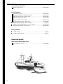
OPERATOR’S MANUAL
TAMD63L/P, TAMD74A

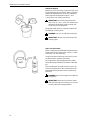
CALIFORNIA
Proposition 65 Warning
Diesel engine exhaust and some of its constituents are known
to the State of California to cause cancer, birth defects, and
other reproductive harm.
This operator’s manual is also available in the following languages:
Diese Betriebsanleitung ist auch auf
Deutsch erhältlich.
Ein Bestellcoupon ist am Ende der Betriebs-
anleitung zu finden.
Ce manuel d’instructions peut être
commandé en français.
Vous trouverez un bon de commande à la fin
du manuel d’instructions.
Este libro de instrucciones puede soli-
citarse en español.
El cupón de pedido se encuentra al final del
libro.
Den här instruktionsboken kan bestäl-
las på svenska.
Beställningskupong finns i slutet av instrukti-
onsboken.
Questo manuale d’istruzioni può esse-
re ordinato in lingua italiana.
Il tagliando per l’ordinazione è riportato alla
fine del manuale.
Dit instructieboek kan worden besteld
in het Nederlands.
De bestelcoupon vindt u achter in het instruc-
tieboek.
Denne instruktionsbog kan bestilles
på dansk.
Bestillingskupon findes i slutningen af instruk-
tionsbogen.
Tämän ohjekirjan voi tilata myös suo-
menkielisenä.
Tilauskuponki on ohjekirjan lopussa.
Este manual de instruções pode ser
encomendado em português.
O talão de requerimento encontra-se no fim
do manual.
Áõôü ôï åã÷åéñßäéï ÷ñÞóçò
äéáôßèåôáé óôçí áããëéêÞ ãëþóóá.
Ãéá íá ðáñáããåßëåôå Ýíá áíôßôõðï,
óõìðëçñþóôå ôç öüñìá ðïõ âñßóêåôáé óôï
ôÝëïò áõôïý ôïõ åã÷åéñéäßïõ ÷ñÞóçò.

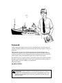
Foreword
Volvo Penta marine engines are used all over the world today. They are used in all
possible operating conditions for professional as well as leisure purposes. That’s not
surprising.
After more than 90 years as an engine manufacturer and after delivering over
500,000 marine engines, the Volvo Penta name has become a symbol of reliability,
technical innovation, top of the range performance and long service life. We also be-
lieve that this is what you demand and expect of your Volvo Penta engine.
We would like you to read this operator’s manual thoroughly and consider the advice
we give on running and maintenance before you cast off on your maiden voyage so
that you will be ensured of fulfilling your expectations.
With warm regards
AB VOLVO PENTA
IMPORTANT! These instructions do not contain descriptions of controls or
operation for boats with waterjet. If your boat is equipped with Volvo Penta
waterjet, this information can be found in the operator’s manual that came
with the waterjet.

2
Contents
Safety information .............................................. 3
Boat trips ............................................................ 4
Maintenance and service.................................... 6
Introduction ........................................................ 8
Environmental responsibility ............................... 8
Running in .......................................................... 8
Fuel and oil......................................................... 8
Service and spare parts...................................... 8
Certified engines................................................. 9
Warranty............................................................. 9
Identification number .......................................... 11
Presentation........................................................ 11
Instruments......................................................... 13
Instrument panels ............................................... 13
Control panels .................................................... 14
Warning displays ................................................ 14
Starting switch .................................................... 15
Controls............................................................... 16
Single lever control ............................................. 16
Dual lever control................................................ 17
Starting the engine ............................................. 18
Measures before start......................................... 18
Starting procedure .............................................. 18
Operation ............................................................ 20
Check the instruments........................................ 20
Alarms and fault indication.................................. 20
Cruising speed ................................................... 21
Manoeuvring....................................................... 21
Accessories........................................................ 23
Stopping the engine ........................................... 24
Before stopping .................................................. 24
Stop.................................................................... 24
Emergency stop ................................................. 24
After stopping ..................................................... 25
Anti-freezing measures....................................... 25
Breaks in operation............................................. 25
Maintenance schedule ....................................... 26
Maintenance........................................................ 29
Engine, general .................................................. 29
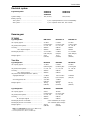
Lubricating system.............................................. 32
Freshwater system ............................................. 35
Seawater system................................................ 43
Fuel system ........................................................ 47
Electrical system ................................................ 52
Electrical component diagrams........................... 56
Reverse gear...................................................... 58
Inhibiting ............................................................. 60
Troubleshooting ................................................. 62
Start using auxiliary batteries.............................. 63
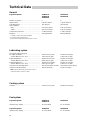
Technical Data .................................................... 64
Engine ................................................................ 64
Reverse gear...................................................... 65
© 2001 AB VOLVO PENTA
We reserve the right to make revisions. Printed on environment-friendly paper
(Cover: National Administration of Shipping and Navigation, permit 9809095)

3
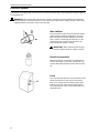
Safety information
Read this chapter thoroughly. It concerns your safety. This section describes how safety information is presented
in this manual and on the product. It also includes a summary of basic safety regulations for boat trips and main-
tenance of the engine.
Make sure you are in possession of the right operator’s manual before reading on. If this is not the case,
please get in touch with your Volvo Penta dealer.
Incorrect handling can cause personal injury or damage to the product and/or property.
Consequently, please read this operator’s manual thoroughly before starting the engine
or carrying out maintenance and service. If anything is still not clear or if you are not sure
of any points, please get in touch with your Volvo Penta dealer for assistance.
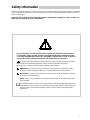
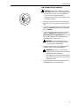
This symbol is used throughout the operator’s manual and on the product to bring your atten-
tion to points of safety-related information. Always read such information thoroughly.
Warnings in the operator’s manual have the following order of priority:
WARNING! Warns for the risk of physical injury, severe damage to the product or other
property or serious malfunctions that may occur if the instructions are not followed.
IMPORTANT! Used to call your attention to points that may cause malfunctions or damage
to the product or other property.
NOTE! Used to call your attention to important information that can facilitate working meth-
ods or handling.
This symbol is used in certain cases on our products to refer to important information found
in the operator’s manual. Make sure all warning and information symbols on the engine and
transmission are easily visible and legible. Replace symbols that have been damaged or
painted over.

4
Safety information
Safety regulations for boat trips
The new boat
Read operator’s manuals and other information ac-
companying the new boat thoroughly. Accustom
yourself with handling the engine, controls and other
equipment in a safe and correct manner.
If this is your first boat or if it is a type you are not
used to, we recommend practising manoeuvring the
boat in a peaceful environment. Learn the sea-going
and manoeuvring characteristics at different speeds
and in varying weather and load conditions before
casting off on your “real” maiden voyage.
Remember that when operating a boat, you have a
legal responsibility to be aware of and follow regula-
tions concerning traffic and safety at sea. Inform
yourself of the regulations that apply to you and your
waters by getting in touch with the relevant authorities
or marine safety organisation.
Attending some kind of boat handling course is a
good idea. We recommend getting in touch with a re-
gional boat or marine safety organisation to help you
locate a suitable course.
Accidents and other incidents
Sea rescue statistics show that deficient maintenance
of boats and engines together with defective safety
equipment often causes accidents and other incidents
at sea.
Make sure your boat and engine are maintained in
accordance with directions in the operator’s manuals
and that the safety equipment on board is in good
working order.
Daily inspection
Make a habit of visually inspecting the engine and en-
gine room before starting (before starting the en-
gine) and after stopping (when the engine has been
turned off). This will help you to quickly detect any
fuel, coolant or oil leaks and any other abnormalities
that have occurred or are about to occur.
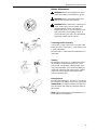
Manoeuvring
Avoid violent and rapid rudder movement and gear
shifting. There is a risk of the passengers falling down
or falling overboard.
A rotating propeller can cause serious injury. Make
sure there is nobody in the water before engaging for-
ward/reverse. Never run close to bathers or in places
where you have reason to believe there are people in
the water.
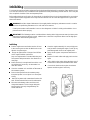
Filling fuel
There is a risk of fire and explosion when filling fuel.
Smoking is prohibited and the engine must be turned
off.
Never overfill the tank. Close the filler cap securely.
Use only fuel recommended in the operator’s manual.
The incorrect grade of fuel can disturb operation or
cause breakdown. This can also lead to the control
rod jamming on diesel engines, which will overrev the
engine and risk damaging machinery and causing
personal injury.
Do not start the engine
Do not start or run the engine with a suspected fuel or
LPG leak in the boat, nor when you are close to or in
a discharge of explosive media, etc. There is risk for
fire and/or explosion in explosive surroundings.

5
Safety information
Carbon monoxide poisoning
When a boat is moving forward, it will cause a certain
vacuum to form behind the boat. In unfortunate cir-
cumstances, the suction from this vacuum can be so
great that the exhaust gases from the boat are drawn
into the cockpit or cabin and cause carbon monoxide
poisoning.
This problem is most prevailant on high, wide boats
with abrupt stern. In certain conditions, however, this
suction can be a problem on other boats, e.g. when
running with the cover up. Other factors that can in-
crease the effect of the suction are wind conditions,
load distribution, swells, trim, open hatches and port-
holes, etc.
Most modern boats, however, are designed in such a
way that this problem is very rare. If suction should
arise anyway, do not open hatches or portholes at the
fore of the boat. Surprisingly, this will otherwise in-
crease the suction. Try changing speed, trim or load
distribution instead. Try taking down/opening or in
any other way changing the setup of the cover as
well. Get in touch with your boat dealer for help in ob-
taining the best solution for your boat.
Remember
Safety equipment: life jackets for everyone on board, communication equipment, distress rockets,
approved fire extinguisher, bandages, life buoy, anchor, paddle, torch, etc.
Spare parts and tools: Impeller, fuel filter, fuses, adhesive tape, hose clips, engine oil, propeller
and tools for tasks it may be necessary to perform.
Plan your desired route from the charts. Calculate distance and fuel consumption. Listen to
weather reports.
Inform relations of your planned route for long trips. Remember to inform of changed plans or de-
lays.
Inform the people on board of where the safety equipment is located and how it works. Make sure
there is more than one person on board that knows how to start and manoeuvre the boat safely.
This list should be supplemented with necessary safety equipment depending on the type of boat,
where and how it is being used, etc. We recommend you get in touch with a regional boat or marine
safety organisation to obtain more detailed marine safety information.

6
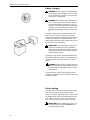
Safety information
Safety directions for maintenance and service
Preparations
Knowledge
The operator’s manual contains directions for per-
forming normal maintenance and service in a safe
and correct manner. Read the directions carefully be-
fore starting work.
More detailed service literature is available from your
Volvo Penta dealer.
Never perform a task unless you are absolutely sure
how it is to be carried out, call your Volvo Penta deal-
er for assistance instead.
Stop the engine
Stop the engine before opening or dismantling the en-
gine hatch/hood. Maintenance and service must be
carried out with the engine stationary unless stated
otherwise in the instructions.
Prevent inadvertent start of the engine by removing
the starter key and turning off the power with the main
switch, locking it in the off position. Place a warning
sign in the driver position stating that service is in
progress.
Working on or approaching a running engine is a
safety hazard. Loose clothing, hair, fingers or a
dropped tool can fasten in rotating parts and cause
serious bodily injury. Volvo Penta recommend leaving
all work requiring the engine to be running to an
authorised Volvo Penta service centre.
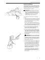
Lifting the engine
Always use the lifting eyes mounted on the engine (or
reverse gear) when lifting the engine. Always make
sure lifting equipment is in good condition and con-
structed for the lift (engine weight together with possi-
ble reverse gear and extra equipment). Use an ad-
justable lifting boom to ensure safe handling when lift-
ing the engine. All chains and wires must run parallel
with each other and as much at right-angle as possi-
ble to the top of the engine. Note that any extra equip-
ment mounted on the engine can change the centre
of gravity. Special lifting devices may be required to
obtain the right balance and safe handling. Never per-
form service on an engine suspended only from a lift-
ing device.
Before starting
Refit all guards and covers that have been removed
before starting the engine. Make sure there are no
tools or other objects left on the engine.
A turbocharged engine must never be started without
the air filter fitted. The rotating compressor wheel in
the turbocharger can cause severe personal injury.
There is also a risk of foreign objects being drawn in
and causing mechanical damage.
Fire and explosion
Fuel and lubricants
All fuel, most lubricants and many chemicals are
flammable substances. Always read and follow the di-
rections on the packaging.
Work performed on the fuel system must be done on
a cold engine. Fuel leaks and spills on hot surfaces or
electrical components can cause fires.
Keep oil- and fuel-drenched rags and other hazard-
ous materials where they are safe in case of fire. Oil
drenched rags can self-ignite in certain conditions.
Never smoke when refuelling, topping up with oil or
when in the vicinity of the fuel station or engine room.
Non-original parts
Components in fuel, ignition and electrical systems on
Volvo Penta engines are designed and manufactured
to minimize the risk of explosion and fire in compli-
ance with existing legislation.
The use of non-original parts can result in explosion
or fire.
Batteries
Batteries contain and generate oxyhydrogen gas, es-
pecially when charging. Oxyhydrogen is easily ignited
and extremely explosive.
Smoking, naked flames and sparks must never occur
in or close to the batteries or battery compartment.
A faulty battery connection or jumper cable can gen-
erate sparks which can cause the battery to explode.
Start spray
Never use start spray or similar start help. Explosions
can occur in the intake manifold. Risk for personal in-
jury.

7
Safety information
Hot surfaces and fluids
A hot engine always involves risk for burn injuries.
Take care with hot surfaces. E.g.: exhaust manifold,
turbocharger, oil pan, charge air pipe, starting heater,
hot coolant and warm lubricant in pipes and hoses.
Carbon monoxide poisoning
Start the engine in well ventilated spaces only. When
running in confined spaces, the exhaust gases and
crankcase gases must be evacuated.
Chemicals
Most chemicals such as glycol, anti-corrosion agent,
preservatives, degreasing agent, etc., are hazardous
to health. Always read and follow the directions on
the packaging.
Certain chemicals such as preservatives are flamma-
ble and harmful to inhale. Provide good ventilation
and use breathing protection when spraying. Always
read and follow the directions on the packaging.
Store chemicals and other hazardous materials out of
reach of children. Leave left over or used chemicals
to a destruction plant.
Cooling system
There is a risk of water entering when working on the
seawater system. Therefore, stop the engine and
close the sea cock before starting work.
Avoid opening the coolant filler cap when the engine
is warm. Steam or hot coolant may spurt out and
cause burn injuries.
If the filler cap, coolant pipe, cock, etc., must never-
theless be opened or dismantled while the engine is
warm, the filler cap must be opened carefully to re-
lease the pressure before removing it completely and
starting work. Note that the coolant can still be hot
and cause burn injuries.
Lubricating system
Hot oil can cause burn injuries. Avoid skin contact
with warm oil. Make sure the lubricating system is
depressurised before starting work. Never start or run
the engine with the oil filler cap removed or there will
be a risk of the oil being thrown out.
Fuel system
Always protect your hands when carrying out leak de-
tection. Escaping fluids under pressure can pierce
bodily tissue and cause serious injury. Risk of blood
poisoning.
Always cover the alternator if it is located under the
fuel filter. Fuel spills can damage the alternator.
Electrical system
Turn off the power
Before starting work on the electrical system, the en-
gine must be stopped and the powered turned off with
the main switch/switches. Shore power to the engine
heater, battery charger or other extra equipment fitted
to the engine must be disconnected.
Batteries
Batteries contain a highly corrosive electrolyte. Pro-
tect your eyes, skin and clothing when charging and
handing batteries. Always use protective goggles and
gloves.
In case of splashes on the skin, wash with soap and
plenty of water. In case of splashes in the eyes, rinse
immediately with plenty of water and call a doctor.

8
Introduction
The operator’s manual has been produced to give you the greatest benefit of your Volvo Penta marine engine. It
contains the information necessary to handle and maintain your engine in a safe and correct manner. We would
like you to read this operator’s manual thoroughly and learn how to handle the engine, controls and other equip-
ment in a safe manner before casting off for your maiden voyage.
Keep the operator’s manual handy at all times. Keep it safe and do not forget to hand it over to the new owner if
you ever sell your boat.
Care of the environment
We would all like to live in a clean and healthy envi-
ronment. Somewhere where we can breathe clean
air, see healthy trees, have clean water in our lakes
and oceans, and are able to enjoy the sunshine with-
out being worried about our health. Unfortunately, this
cannot be taken for granted nowadays but is some-
thing we must work together to achieve.
As a manufacturer of marine engines, Volvo Penta
has a special responsibility, why care of the environ-
ment is a core value in our product development. To-
day, Volvo Penta has a broad range of engines where
progress has been made in reducing exhaust emis-
sions, fuel consumption, engine noise, etc.
We hope you will take care in preserving these quali-
ties. Always follow any advice given in the operator’s
manual concerning fuel grades, operation and main-
tenance and you will avoid causing unnecessary in-
terference to the environment. Get in touch with your
Volvo Penta dealer if you notice any changes such as
increased fuel consumption exhaust smoke.
Adapt speed and distance to avoid wash and noise
disturbing or injuring animal life, moored boats, jetties,
etc. Leave islands and harbours in the same condi-
tion as you want to find them. Remember to always
leave hazardous waste such as waste oil, coolant,
paint and wash residue, flat batteries, etc., for dis-
posal at a destruction plant.
Our joint efforts will make a valuable contribution to
our environment.
Running in
The engine must be “run in” during the first 10 hours
of operation as follows:
Run the engine under normal operation. Do not run it
at full power except for short periods. Never run the
engine for long periods at constant rpm during this
time.
A high consumption of lubricant is normal during the
running in period. Therefore, check the oil level more
often than recommended.
The prescribed warranty inspection “First Service In-
spection” must be carried out during this first period of
operation. For more information: See Warranty and
Service Book.
Fuel and oil
Use only fuel and oil grades as recommended in the
operator’s manual. Other grades can cause opera-
tional problems, increase fuel consumption and have
long-range effects on engine service life.
Always change oil, oil filter and fuel filter according to
prescribed intervals.
Service and spare parts
Volvo Penta marine engines are designed for high
operational reliability and long service life. They are
constructed to withstand the marine environment
while also affecting it as little as possible. Through
regular service and the use of Volvo Penta original
spare parts, these qualities will be retained.
The worldwide Volvo Penta network of authorised
dealers is at your service. They are specialists in
Volvo Penta products and stock accessories, original
spare parts, test equipment and the special tools re-
quired to perform high-quality service and repairs.
Always follow the maintenance intervals specified in
the operator’s manual and remember to specify the
engine/transmission number when ordering service
and spare parts.

9
Introduction
Certified engines
It is essential that owners and operators of emission
certified engines used in areas where exhaust emis-
sions are regulated by law are aware of the following
points:
A certification involves the engine type being
checked and approved by applicable authorities. En-
gine manufacturers guarantee that all engines of the
same type correspond with the certified engine.
This puts special demands on the maintenance
and service of your engine:
Maintenance and service intervals recommended
by Volvo Penta must be followed.
Only Volvo Penta original spare parts may be
used.
Service of injector pumps, pump settings and in-
jectors must always be performed at an
authorised Volvo Penta workshop.
The engine must not be modified in any way with
the exception of accessories and service kits ap-
proved by Volvo Penta for use on the engine.
Installation modifications must not be made to the
engine exhaust pipe or inlet channels.
Any sealed sections must not be broken by any-
one other than authorised personnel.
Otherwise, the general directions concerning running,
care and maintenance given in the operator’s manual
apply.
IMPORTANT! Neglected or deficient mainte-
nance/service and the use of non-original spare
parts will entail Volvo Penta renouncing any re-
sponsibility for the engine corresponding to the
certified version. Volvo Penta will not compen-
sate for damage and/or costs arising from the
above.
Warranty
Your new Volvo Penta marine engine is covered by a limited warranty complying with the conditions
and instructions given in the Warranty and Service Book.
Note that AB Volvo Penta’s responsibility is limited to what is specified in the Warranty and Service
Book. Read it carefully as soon as possible after delivery. It contains important information concerning
the warranty card, service, maintenance and what the owner is responsible to be aware of, check and
perform. Warranty liability will otherwise be declined completely or fully by AB Volvo Penta.
Get in touch with your Volvo Penta dealer if you have not received a Warranty and Service Book
or a copy of the warranty card.

10
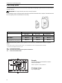
Introduction
Identification number
Type plates with identification number can be found on the engine and transmission. This information must al-
ways be used as a reference when ordering service and spare parts. Similar plates can probably be found on
your boat and its equipment. Make a note of the information in the space below and make a copy of this page so
the information is available even if the boat should be stolen.
The appearance and location of the type plates is shown below. The numbers in brackets refer to the location of
the identification number on the type plate.
Engine
Product designation (1) ......................................................................................................
Serial and basic engine number (2) ....................................................................................
Product number (3).............................................................................................................
Certification, IMO
Decal, part No. (4) ...............................................................................................................
Approval No. (5) ..................................................................................................................
Transmission
Product designation (6) .......................................................................................................
Serial number (7).................................................................................................................
Product number (8)..............................................................................................................
Engine and transmission decal
Reverse gear plate
Certification decal
Engine plate
Certification plate
(6)
(7)
(8)
XXXX (6)
XXXXXXXXXX (7)
IMPORTANT ENGINE INFORMATION
AB Volvo Penta, Sweden VP xxxx
(4)
IMO
ENGINE FAMILY xxxx ENGINE MODEL xxxx (1)
TEST CYCLES xxxx POWER (kW/RPM) xxxx
IMO APP NO. MTC xxxx
(5)
IMO APP NO. EPA –
ENGINE SERIAL NO. AVAILABLE ON ENGINE IDENTIFICATION PLATE
CERTIFICATE AND TECHNICAL FILE: AVAILABLE ON WWW.PENTA.VOLVO.SE
THIS ENGINE IS CERTIFIED BY SWEDISH ACCREDITED ORGANISATION MTC
IN ACCORDANCE WITH IMO NOX TECHNICAL CODE ANNEX VI MARPOL 73/78

11
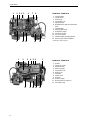
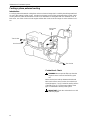
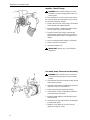
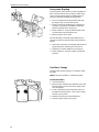
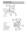
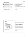
Presentation
TAMD63L, TAMD63P and TAMD74A are in-line,
direct injection, 6-cylinder, 4-stroke marine diesel
engines. They are equipped with turbocharger and fit-
ted with either a heat exchanger for thermostat-
regulated freshwater cooling or connections for keel
cooling.
The engines are equipped with a seawater cooled
charge air cooler. The charge air cooler lowers the
temperature of the inlet air to the engine after it has
been compressed in the turbocharger. This allows
high power output while keeping combustion and
exhaust temperatures at a suitable level.
The exhaust manifold and turbocharger are fresh-
water cooled to reduce heat radiation to the engine
room.
These engines are equipped with mechanical fuel
control.
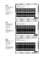
TAMD63L-A, TAMD63L-B, TAMD63P-A
1. Fuel fine filters
2. Smoke limiter
3. Coolant filler cap
4. Injection pump
5. Oil filler cap
6. Distribution box with semi-automatic
fuses
7. Turbocharger
8. Water cooled exhaust pipe elbow
(option)
9. Reverse gear (ZF (MPM) IRM220A-1)
10. Wastegate valve (TAMD63P)
11. Oil dipstick, engine
12. Fuel shut-off valve
13. Oil cooler, engine
14. Flexible engine mounting (option)
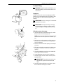
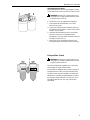
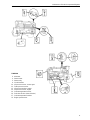
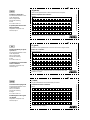
TAMD63L-A, TAMD63L-B, TAMD63P-A
1. Filter for crankcase ventilation
2. Air filter
3. Charge air cooler
4. Oil filler cap
5. Expansion tank
6. Coolant filler cap
7. Heat exchanger
8. Alternator
9. Sea water pump
10. By-pass filter for engine oil
11. Oil filter, engine
12. Starter motor
13. Oil dipstick, engine
14. Oil dipstick, reverse gear
14 13 12 11 10 9
1234567 8
12 34 5 6 78
14 13 12 11 10 9

12
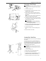
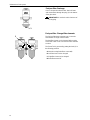
Presentation
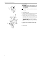
TAMD74A-A, TAMD74A-B
1. Fuel fine filters
2. Smoke limiter
3. Oil filler cap
4. Coolant filler cap
5. Injection pump
6. Distribution box with semi-automatic
fuses
7. Turbocharger*
8. Exhaust pipe elbow
9. Oil dipstick, engine
10. Fuel shut-off valve
11. Oil cooler, engine
12. Flexible engine mounting (option)
13. Reverse gear (TD MG5091DC)
* TAMD74A-B: With wastegate.
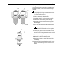
TAMD74A-A, TAMD74A-B
1. Air filter
2. Charge air cooler
3. Expansion tank
4. Heat exchanger
5. Coolant filler cap
6. Oil filler cap
7. Alternator
8. Starter motor
9. Oil sump
10. Oil filter, engine
11. By-pass filter for engine oil
12. Sea water pump
123456 7
8 9 10 11 12
12345 6 78
91011 1213

13
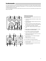
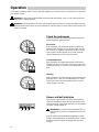
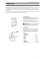
Instruments
This chapter describes the Volvo Penta instruments that are available for your engine. Note that that tachometer,
oil gauge, temperature gauge, charge gauge, starting switch, etc., that are shown here as panel mounted may be
mounted separately in some boats.
If your boat is fitted with instruments not described here and you are not sure of their function, please get in touch
with your boat dealer.
Instrument panels
Instrumentation for the main control position and aux-
iliary control position.
1. Temperature gauge. Indicates the engine coolant
temperature.
2. Oil pressure gauge. Indicates the pressure of the
engine lubricant.
3. Voltmeter. Indicates the charge voltage from the
alternator when the engine is running and the bat-
tery voltage when the engine is stopped.
4. Tachometer. Indicates the speed of the engine in
rpm.
5. Hour counter. Shows the total number of engine
running hours as a decimal number.
6. Press button for testing and acknowledging
alarms (see next page “Warning displays”).
7. Siren for acoustic alarm that sounds if one of the
warning lamps comes on.
8. Warning display (see next page “Warning dis-
plays”, pos 1–4).
9. Starting switch (see next page).
10. Press button for instrument illumination.
11. Oil pressure gauge. Indicates the oil pressure in
the reverse gear.
12. Charge air pressure gauge. Indicates the turbo-
charger boost pressure.
123
45678910
85 910
467
11
12

14
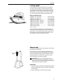
Instruments
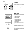
Control panels
Control panels for the main control position and auxil-
iary control position.
1. Siren for acoustic alarm that sounds if one of the
warning lamps comes on.
2. Press button for instrument illumination.
3. Press button for testing and acknowledging
alarms (see “Warning displays” below).
4. Starting switch.
5. Start button.
6. Stop button.
Warning displays
If the acoustic alarm sounds, one of the warning dis-
play lamps will immediately start to flash to indicate
the cause of the alarm.
1. Coolant temperature too high.
2. Lubricant pressure too low.
3. Alternator not charging
4. Not used
5. Lubricant level too low* (accessory).
6. Coolant level too low* (accessory).
7. Water in fuel pre-filter (accessory).
8. Auxiliary (accessory).
* Warns for low level with stationary engine and starter key in position I
(“Drive position”). Refill to correct level before starting the engine.
After an alarm
Press the “Alarm test” button to acknowledge and
terminate the acoustic alarm. The relevant warning
lamp will continue to flash until the fault has been
rectified.
Alarm test
After pressing the “Alarm test” button, the warning
lamps will come on and the acoustic alarm will start to
sound. Make a habit of always performing an alarm
test before starting.
1
2
4
3
5
678
5 6
2
3
1
12
3
4

15
Instruments
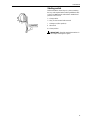
Starting switch
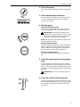
Delivered with the starter keys is a plate containing
the key code required when ordering additional start-
er keys. Do not keep the code where unauthorized
persons can access it.
S = Stop position.
0 = Key can be inserted and removed.
I = Voltage on (drive position).
II = Not used
III = Start position.
IMPORTANT! Read the starting instructions in
the chapter “Starting the engine”.

16
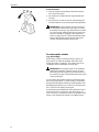
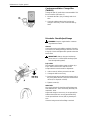
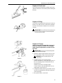
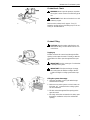
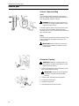
Single lever control
Manoeuvring
Single lever control operates shifting and engine speed
from the same lever (1).
N = Neutral position (reverse disengaged and engine
idling).
F = Reverse gear engaged for moving forwards.
R = Reverse gear engaged for moving backward.
= Engine speed control.
A neutral position switch is available as an accessory that
allows the engine to be started only when the reverse gear
is disengaged.
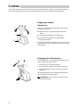
Controls
This chapter describes the Volvo Penta controls that are available for your engine. If your boat is fitted with con-
trols not described here and you are not sure of their function, please get in touch with your boat dealer.
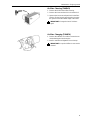
Disengaging the shifting function
The shifting function can easily be disengaged to that the
lever only affects the engine speed.
1. Put the lever (1) in neutral position (N).
2. Press the button (2) while moving the lever forward.
3. Release the button. The lever now affects the engine
speed only.
The disengagement will cease automatically when the le-
ver is moved back to neutral position.
IMPORTANT! Take care not to engage the reverse
gear unintentionally.
T
T
2
1

17
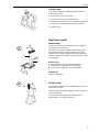
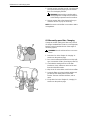
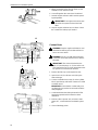
Controls
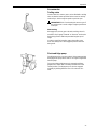
Friction brake
The control is fitted with an adjustable friction brake for
engine speed control.
1. Remove the cover on the control.
2. Set the lever to half acceleration/reverse.
3. Adjust the friction brake. Turn clockwise for stiffer lever
movement and anticlockwise for lighter movement.
4. Refit the cover.
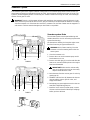
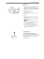
Dual lever control
Manoeuvring
The dual lever control has separate levers for shifting (1)
and engine speed control (2).
Control A has a mechanic detent so that shifting can be
performed only when the engine speed lever is in idle
speed position. A neutral position switch is available that
allows the engine to be started only when the reverse gear
is disengaged.
Black lever (1):
N = Neutral position. Reverse gear disengaged.
F = Reverse gear engaged for moving forwards.
R = Reverse gear engaged for moving backward.
Red lever (2):
Engine speed control.
Friction brake
The controls are fitted with an adjustable friction brake for
engine speed control.
Adjust the friction brake by turning the screw (control A) or
the lever (control B).
Turn clockwise (+) for stiffer lever movement and
anticlockwise (–) for lighter movement.
B
A
2
1

18
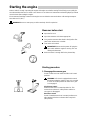
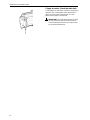
Starting the engine
Make a habit of “visually” inspecting the engine and engine room before starting This will help you to quickly de-
tect abnormalities that have occurred or are about to occur. Make sure instruments and warning displays indicate
normal values after starting the engine.
We recommend installing a heater for the engine room to minimize start smoke when cold starting at tempera-
tures below +5
o
C (41
o
F).
WARNING! Never use start spray or similar start help. Risk for explosion!
Measures before start
Open the fuel cock
Open the seawater cock where appropriate
Carry out the measures described in “Daily before first
start” in the maintenance schedule.
Turn on the main switch
IMPORTANT! Never turn the power off using the
main switch while the engine is running. This can
damage the alternator.
Make sure there is enough fuel for the planned trip.
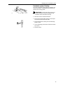
Starting procedure
1. Disengage the reverse gear
Put the control lever into neutral and idle on all control
positions
WARNING! If the boat is equipped with controls
that allow starting the engine in gear, it is essential
to check all control positions to make sure a gear
is not engaged.
Single lever control
Make sure the lever is in neutral position “N”. This
means the accelerator is in idle position and the re-
verse gear is disengaged.
Dual lever control
Put the forward/reverse lever in neutral position to en-
able starting. Move the accelerator all the way back
(idle position).
La pagina si sta caricando...
La pagina si sta caricando...
La pagina si sta caricando...
La pagina si sta caricando...
La pagina si sta caricando...
La pagina si sta caricando...
La pagina si sta caricando...
La pagina si sta caricando...
La pagina si sta caricando...
La pagina si sta caricando...
La pagina si sta caricando...
La pagina si sta caricando...
La pagina si sta caricando...
La pagina si sta caricando...
La pagina si sta caricando...
La pagina si sta caricando...
La pagina si sta caricando...
La pagina si sta caricando...
La pagina si sta caricando...
La pagina si sta caricando...
La pagina si sta caricando...
La pagina si sta caricando...
La pagina si sta caricando...
La pagina si sta caricando...
La pagina si sta caricando...
La pagina si sta caricando...
La pagina si sta caricando...
La pagina si sta caricando...
La pagina si sta caricando...
La pagina si sta caricando...
La pagina si sta caricando...
La pagina si sta caricando...
La pagina si sta caricando...
La pagina si sta caricando...
La pagina si sta caricando...
La pagina si sta caricando...
La pagina si sta caricando...
La pagina si sta caricando...
La pagina si sta caricando...
La pagina si sta caricando...
La pagina si sta caricando...
La pagina si sta caricando...
La pagina si sta caricando...
La pagina si sta caricando...
La pagina si sta caricando...
La pagina si sta caricando...
La pagina si sta caricando...
La pagina si sta caricando...
La pagina si sta caricando...
La pagina si sta caricando...
La pagina si sta caricando...
La pagina si sta caricando...
La pagina si sta caricando...
La pagina si sta caricando...
La pagina si sta caricando...
La pagina si sta caricando...
-
 1
1
-
 2
2
-
 3
3
-
 4
4
-
 5
5
-
 6
6
-
 7
7
-
 8
8
-
 9
9
-
 10
10
-
 11
11
-
 12
12
-
 13
13
-
 14
14
-
 15
15
-
 16
16
-
 17
17
-
 18
18
-
 19
19
-
 20
20
-
 21
21
-
 22
22
-
 23
23
-
 24
24
-
 25
25
-
 26
26
-
 27
27
-
 28
28
-
 29
29
-
 30
30
-
 31
31
-
 32
32
-
 33
33
-
 34
34
-
 35
35
-
 36
36
-
 37
37
-
 38
38
-
 39
39
-
 40
40
-
 41
41
-
 42
42
-
 43
43
-
 44
44
-
 45
45
-
 46
46
-
 47
47
-
 48
48
-
 49
49
-
 50
50
-
 51
51
-
 52
52
-
 53
53
-
 54
54
-
 55
55
-
 56
56
-
 57
57
-
 58
58
-
 59
59
-
 60
60
-
 61
61
-
 62
62
-
 63
63
-
 64
64
-
 65
65
-
 66
66
-
 67
67
-
 68
68
-
 69
69
-
 70
70
-
 71
71
-
 72
72
-
 73
73
-
 74
74
-
 75
75
-
 76
76


Volvo Penta TAMD63L Manuale utente
- Categoria
- Motore
- Tipo
- Manuale utente
in altre lingue
- English: Volvo Penta TAMD63L User manual
Documenti correlati
-
 Volvo Penta D12 Manuale utente
-
 Volvo Penta D4 Manuale utente
-
Volvo D2-55 Manuale utente
-
Volvo Penta IPS 600 Manuale utente
-
 Volvo Penta AQAD30/DP Instruction book
-
 Volvo Penta Easy Connect Interface Installation Instructions Manual
-
Volvo Penta D2-40 Installation Instructions Manual
-
 Volvo Penta D3 290/DP Installation Instructions Manual
-


Altri documenti
-
Yanmar 6HYM-WET Istruzioni per l'uso
-
Regal 42 Fly-Grande Coupe Manuale del proprietario
-
Graymills Diaphragm One Quarter Inch Pump Polypropylene Manuale del proprietario
-
Bayliner 1983 Explorer Manuale del proprietario
-
Ingersoll-Rand R30 Product Maintenance Information
-
Pentair JUNG PUMPEN SIMER 4 Manuale utente
-
Mammoth APD Guida d'installazione
-
Zumex Speed Pro Tank Podium Manuale utente
-
 Seeley TBSI Manuale del proprietario
