WAGO Fieldbus Coupler Modbus TCP M12 Manuale utente
- Categoria
- Networking
- Tipo
- Manuale utente

Manual
WAGO I/O System 750 XTR
750-364/040-010
FC MODBUS TCP M
12 4G XTR
Fieldbus Coupler Modbus TCP M12; 4th Generation;
Extreme
Version 1.1.0

2 WAGO I/O System 750 XTR
750-364/040-010 FC MODBUS TCP M12 4G XTR
Manual
Version 1.1.0
© 2021 WAGO Kontakttechnik GmbH & Co. KG
All rights reserved.
The following applies for Modbus
®
: Modbus
®
is a registered trademark of
Schneider Electric, licensed to the Modbus Organization, Inc.
WAGO Kontakttechnik GmbH & Co. KG
Hansastraße 27
D-32423 Minden
Phone: +49 (0) 571/8 87 – 0
Fax: +49 (0) 571/8 87 – 1 69
Web: www.wago.com
Technical Support
Phone: +49 (0) 571/8 87 – 4 45 55
Fax: +49 (0) 571/8 87 – 84 45 55
Every conceivable measure has been taken to ensure the accuracy and
completeness of this documentation. However, as errors can never be fully
excluded, we always appreciate any information or suggestions for improving the
documentation.
We wish to point out that the software and hardware terms as well as the
trademarks of companies used and/or mentioned in the present manual are
generally protected by trademark or patent.
WAGO is a registered trademark of WAGO Verwaltungsgesellschaft mbH.

WAGO I/O System 750 XTR Table of Contents 3
750-364/040-010 FC MODBUS TCP M12 4G XTR
Manual
Version 1.1.0
Table of Contents
1 Notes about this Documentation ............................................................. 8
1.1 Validity of this Documentation................................................................. 8
1.2 Copyright ................................................................................................ 8
1.3 Symbols ................................................................................................. 9
1.4 Number Notation .................................................................................. 11
1.5 Font Conventions ................................................................................. 11
2 Important Notes ...................................................................................... 12
2.1 Legal Bases .......................................................................................... 12
2.1.1 Subject to Changes .......................................................................... 12
2.1.2 Personnel Qualifications .................................................................. 12
2.1.3 Use of the 750 Series in Compliance with Underlying Provisions ..... 12
2.1.4 Technical Condition of Specified Devices......................................... 13
2.1.4.1 Disposal ...................................................................................... 13
2.1.4.1.1 Electrical and Electronic Equipment ........................................ 13
2.1.4.1.2 Packaging ............................................................................... 14
2.2 Safety Advice (Precautions) ................................................................. 15
2.3 Special Use Conditions for ETHERNET Devices .................................. 18
3 System Description ................................................................................. 19
3.1 Labeling ................................................................................................ 21
3.1.1 Labeling Symbols ............................................................................. 21
3.1.2 Manufacturing Number ..................................................................... 22
3.1.3 Hardware Address (MAC-ID) ........................................................... 22
3.2 Update .................................................................................................. 23
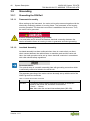
3.3 Storage, Assembly and Transport ........................................................ 24
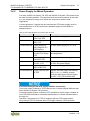
3.4 Power Supply ....................................................................................... 25
3.4.1 Overcurrent Protection ..................................................................... 25
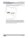
3.4.2 Isolation ........................................................................................... 26
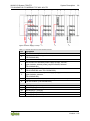
3.4.3 System Supply ................................................................................. 27
3.4.3.1 Connection .................................................................................. 27
3.4.3.2 Dimensioning ............................................................................... 28
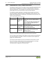
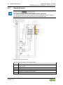
3.4.4 Field Supply ..................................................................................... 30
3.4.4.1 Connection .................................................................................. 30
3.4.4.2 Fusing via Power Supply Module ................................................. 33
3.4.4.3 Fusing External ........................................................................... 35
3.4.5 Power Supply for Mixed Operation ................................................... 37
3.4.6 Supplementary Power Supply Regulations ...................................... 38
3.4.7 Supply Example ............................................................................... 40
3.4.8 Power Supply Units .......................................................................... 41
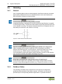
3.5 Grounding............................................................................................. 42
3.5.1 Grounding the DIN Rail .................................................................... 42
3.5.1.1 Framework Assembly .................................................................. 42
3.5.1.2 Insulated Assembly ..................................................................... 42
3.5.2 Grounding Function ......................................................................... 43
3.6 Shielding .............................................................................................. 44
3.6.1 General ............................................................................................ 44
3.6.2 Fieldbus Cables ............................................................................... 44

4 Table of Contents WAGO I/O System 750 XTR
750-364/040-010 FC MODBUS TCP M12 4G XTR
Manual
Version 1.1.0
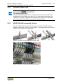
3.6.3 Shielded Signal Lines....................................................................... 45
3.6.4 WAGO Shield Connecting System ................................................... 45
4 Device Description .................................................................................. 46
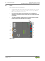
4.1 View ..................................................................................................... 48
4.2 Connectors ........................................................................................... 50
4.2.1 Data Contacts/Local Bus .................................................................. 50
4.2.2 Power Jumper Contacts/Field Supply .............................................. 50
4.2.3 CAGE CLAMP
®
Connectors ............................................................. 51
4.2.4 Device Supply .................................................................................. 53
4.2.5 Fieldbus Connection ........................................................................ 54
4.3 Display Elements .................................................................................. 55
4.4 Operating Elements .............................................................................. 56
4.4.1 Service Interface .............................................................................. 56
4.4.2 Rotary Encoder Switches ................................................................. 57
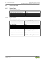
4.5 Technical Data ..................................................................................... 60
4.5.1 Device Data ..................................................................................... 60
4.5.2 System Data .................................................................................... 60
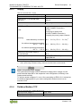
4.5.3 Supply .............................................................................................. 61
4.5.4 Fieldbus Modbus TCP ...................................................................... 61
4.5.5 Accessories ..................................................................................... 62
4.5.6 Connection Type .............................................................................. 62
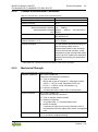
4.5.7 Mechanical Conditions ..................................................................... 62
4.5.8 Climatic Environmental Conditions ................................................... 63
4.5.9 Mechanical Strength ........................................................................ 63
4.6 Approvals ............................................................................................. 65
4.7 Standards and Guidelines .................................................................... 67
5 Mounting .................................................................................................. 72
5.1 Mounting Position ................................................................................. 72
5.1.1 Coordinates Model ........................................................................... 72
5.1.2 Overview of Mounting Positions ....................................................... 72
5.2 Overall Configuration ............................................................................ 74
5.3 Mounting onto Carrier Rail .................................................................... 75
5.3.1 Carrier Rail Properties ...................................................................... 75
5.3.2 WAGO DIN Rail ............................................................................... 76
5.4 Spacing ................................................................................................ 76
5.5 Mounting Sequence .............................................................................. 77
5.6 Inserting and Removing Devices .......................................................... 78
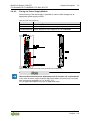
5.6.1 Inserting the Fieldbus Coupler ......................................................... 78
5.6.2 Inserting the I/O Module ................................................................... 79
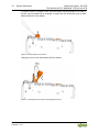
5.6.3 Removing the Fieldbus Coupler ....................................................... 80
5.6.4 Removing the I/O Module ................................................................ 81
6 Connect Devices ..................................................................................... 82
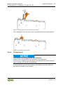
6.1 Data Contacts/Local Bus ...................................................................... 82
6.2 Power Contacts/Field Supply ................................................................ 83
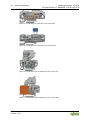
6.3 Connecting a Conductor to the CAGE CLAMP
®
................................... 84
7 Function Description .............................................................................. 85
7.1 Operating System ................................................................................. 85

WAGO I/O System 750 XTR Table of Contents 5
750-364/040-010 FC MODBUS TCP M12 4G XTR
Manual
Version 1.1.0
7.2 Process Data Architecture .................................................................... 86
7.2.1 Basic Structure................................................................................. 86
7.2.2 Process Data EtherNet/IP ................................................................ 87
7.3 Data Exchange ..................................................................................... 88
7.3.1 Memory Space ................................................................................. 89
7.3.2 Addressing ....................................................................................... 89
7.3.2.1 Addressing of I/O Modules .......................................................... 89
7.3.3 Data Exchange between MODBUS/TCP Master and I/O Modules ... 91
8 Commissioning ....................................................................................... 93
8.1 Connecting Client PC and Fieldbus Nodes ........................................... 94
8.2 Determining the IP Address of the PC .................................................. 94
8.3 Assigning the IP Address to the Fieldbus Node .................................... 95
8.3.1 Assigning IP Address via Rotary Encoder Switches ......................... 95
8.3.2 Assigning IP Address via DHCP ...................................................... 97
8.3.2.1 Enable DHCP via "WAGO Ethernet Settings" (without existing
IP address)" ................................................................................. 99
8.3.2.2 Enable DHCP via WBM (with existing IP address) .................... 100
8.3.3 Assigning IP Address via “WAGO Ethernet Settings” ..................... 101
8.3.4 Assigning the IP Address via BootP ............................................... 103
8.3.4.1 Reasons for Failed IP Address Assignment ............................... 105
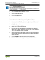
8.4 Apply IP address permanently (option “static“) ................................... 106
8.5 Testing the Function of the Fieldbus Node.......................................... 107
8.6 Preparing the Flash File System ......................................................... 108
8.7 Synchronizing the System Time ......................................................... 110
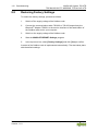
8.8 Restoring Factory Settings ................................................................. 112
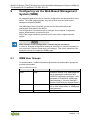
9 Configuring via the Web-Based Management System (WBM) ........... 113
9.1 WBM User Groups ............................................................................. 113
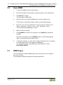
9.2 Open WBM ......................................................................................... 114
9.3 WBM Pages ....................................................................................... 114
9.4 Information ......................................................................................... 115
9.5 Administration ..................................................................................... 116
9.6 Clock .................................................................................................. 118
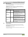
9.7 Miscellaneous ..................................................................................... 120
9.8 Storage Media .................................................................................... 120
9.9 Update ................................................................................................ 121
9.10 Ethernet .............................................................................................. 122
9.11 Protocols ............................................................................................ 126
9.12 SNMP ................................................................................................. 127
9.12.1 SNMP v1/v2c ................................................................................. 128
9.12.2 SNMP V3 ....................................................................................... 129
9.13 SNTP .................................................................................................. 130
9.14 TCP/IP ................................................................................................ 131
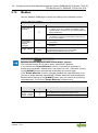
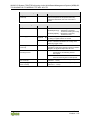
9.15 Modbus .............................................................................................. 132
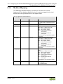
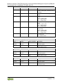
9.16 Modbus Mapping ................................................................................ 134
9.17 I/O Config ........................................................................................... 137
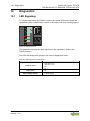
10 Diagnostics............................................................................................ 138
10.1 LED Signaling ..................................................................................... 138
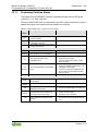
10.1.1 Evaluating Fieldbus Status ............................................................. 139

6 Table of Contents WAGO I/O System 750 XTR
750-364/040-010 FC MODBUS TCP M12 4G XTR
Manual
Version 1.1.0
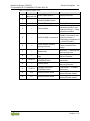
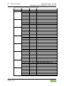
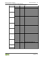
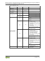
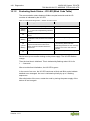
10.1.2 Evaluating Node Status – I/O LED (Blink Code Table) ................... 140
10.2 Fault Behavior .................................................................................... 149
10.2.1 Fieldbus Failure ............................................................................. 149
10.2.2 Local Bus Failure ........................................................................... 149
11 Fieldbus Communication ..................................................................... 151
11.1 Implemented Protocols ....................................................................... 151
11.1.1 Communication Protocols .............................................................. 151
11.1.1.1 IP (Internet Protocol) ................................................................. 151
11.1.1.2 TCP (Transmission Control Protocol) ........................................ 156
11.1.1.3 UDP (User Datagram Protocol) ................................................. 156
11.1.2 Configuration and Diagnostics Protocols ........................................ 157
11.1.2.1 BootP (Bootstrap Protocol) ........................................................ 157
11.1.2.2 DHCP (Dynamic Host Configuration Protocol) ........................... 158
11.1.2.3 HTTP (Hypertext Transfer Protocol) .......................................... 160
11.1.2.4 DNS (Domain Name Systems) .................................................. 160
11.1.2.5 SNTP-Client (Simple Network Time Protocol) ............................ 161
11.1.2.6 FTP-Server (File Transfer Protocol) ........................................... 161
11.1.2.7 SNMP (Simple Network Management Protocol) ........................ 162
11.1.2.7.1 MIB II Description .................................................................. 162
11.1.2.7.2 Traps .................................................................................... 164
11.1.2.8 Syslog Client ............................................................................. 164
11.1.2.8.1 Syslog Messages .................................................................. 165
11.1.2.8.2 Configuration ........................................................................ 166
11.1.3 Application Protocols...................................................................... 167
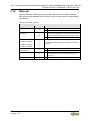
11.2 Modbus Functions .............................................................................. 168
11.2.1 General .......................................................................................... 168
11.2.2 Use of the MODBUS Functions ...................................................... 171
11.2.3 Description of the MODBUS Functions .......................................... 172
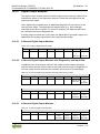
11.2.3.1 Function Code FC1 (Read Coils) ............................................... 173
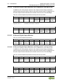
11.2.3.2 Function Code FC2 (Read Discrete Inputs) ............................... 175
11.2.3.3 Function Code FC3 (Read Multiple Registers) ........................... 177
11.2.3.4 Function Code FC4 (Read Input Registers) ............................... 178
11.2.3.5 Function Code FC5 (Write Coil) ................................................. 179
11.2.3.6 Function Code FC6 (Write Single Register) ............................... 180
11.2.3.7 Function Code FC11 (Get Comm Event Counter) ..................... 181
11.2.3.8 Function Code FC15 (Write Multiple Coils) ................................ 182
11.2.3.9 Function Code FC16 (Write Multiple Registers) ......................... 184
11.2.3.10 Function Code FC22 (Mask Write Register) .............................. 185
11.2.3.11 Function Code FC23 (Read/Write Multiple Registers) ............... 186
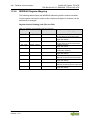
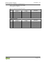
11.2.4 MODBUS Register Mapping .......................................................... 188
11.2.5 Modbus
Registers .......................................................................... 191
11.2.5.1 Accessing Register Values ........................................................ 192
11.2.5.2 Modbus-Watchdog .................................................................... 192
11.2.5.3 Modbus
Watchdog Register ....................................................... 194
11.2.5.4 Diagnostic Registers .................................................................. 198
11.2.5.5 Configuration Registers ............................................................. 199
11.2.5.6 Constant Registers .................................................................... 201
11.2.5.7 Firmware Information Registers ................................................. 203

WAGO I/O System 750 XTR Table of Contents 7
750-364/040-010 FC MODBUS TCP M12 4G XTR
Manual
Version 1.1.0
12 I/O Modules............................................................................................ 208
12.1 Overview ............................................................................................ 208
12.2 Process Data Architecture for Modbus TCP ....................................... 209
12.2.1 Digital Input Modules...................................................................... 210
12.2.1.1 2-Channel Digital Input Modules ................................................ 210
12.2.1.2 8-Channel Digital Input Modules ................................................ 210
12.2.1.3 16-Channel Digital Input Modules .............................................. 210
12.2.2 Digital Output Modules ................................................................... 211
12.2.2.1 2-Channel Digital Output Modules ............................................. 211
12.2.2.2 2-Channel Digital Output Modules with Diagnostics and Input
Data .......................................................................................... 211
12.2.2.3 4-Channel Digital Output Modules ............................................. 211
12.2.2.4 4-Channel Digital Output Modules with Diagnostics and Input
Data .......................................................................................... 212
12.2.2.5 8-Channel Digital Output Modules ............................................. 212
12.2.2.6 8-Channel Digital Output Modules with Diagnostics and Input
Data .......................................................................................... 212
12.2.2.7 16-Channel Digital Output Modules ........................................... 213
12.2.3 Analog Input Modules .................................................................... 214
12.2.3.1 2-Channel Analog Input Modules............................................... 214
12.2.3.2 4-Channel Analog Input Modules............................................... 214
12.2.3.3 3-Phase Power Measurement Module ....................................... 214
12.2.4 Analog Output Modules .................................................................. 216
12.2.4.1 2 Channel Analog Output Modules ............................................ 216
12.2.4.2 4 Channel Analog Output Modules ............................................ 216
12.2.5 Specialty Modules .......................................................................... 217
12.2.5.1 Serial Interfaces with Alternative Data Format ........................... 217
12.2.5.2 SSI Transmitter Interface I/O Modules ....................................... 218
12.2.5.3 Distance and Angle Measurement ............................................. 218
12.2.5.4 Counter Modules ....................................................................... 218
12.2.5.5 CAN Gateway ............................................................................ 220
12.2.6 System Modules ............................................................................ 221
12.2.6.1 System Modules with Diagnostics ............................................. 221
13 Application Examples ........................................................................... 222
13.1 Test of Modbus protocol and fieldbus nodes ....................................... 222
13.2 Visualization and Control using SCADA Software ............................... 222
14 Use in Hazardous Environments ......................................................... 225
14.1 Marking Configuration Examples ........................................................ 226
14.1.1 Marking for Europe According to ATEX and IECEx ........................ 226
14.1.2 Marking for the United States of America (NEC) and Canada
(CEC) ............................................................................................. 230
14.2 Installation Regulations....................................................................... 233
14.2.1 Special Notes including Explosion Protection ................................. 233
14.2.2 Special Notes Regarding UL Hazardous Location .......................... 235
List of Figures ................................................................................................ 236
List of Tables .................................................................................................. 238

8 Notes about this Documentation WAGO I/O System 750 XTR
750-364/040-010 FC MODBUS TCP M12 4G XTR
Manual
Version 1.1.0
1 Notes about this Documentation
Always retain this documentation!
This documentation is part of the product. Therefore, retain the documentation
during the entire service life of the product. Pass on the documentation to any
subsequent user. In addition, ensure that any supplement to this documentation
is included, if necessary.
1.1 Validity of this Documentation
This documentation is only applicable to the “FC MODBUS TCP M12 4G XTR”
(750-364/040-010).
The device FC MODBUS TCP M12 4G XTR 750-364/040-010 shall only be
installed and operated according to the instructions in this manual and the
system description for the WAGO I/O System 750 XTR.
Consider power layout of the WAGO I/O System750 XTR!
In addition to these operating instructions, you will also need the system
description “Design Notes XTR – Guidelines and Recommendations for
Increasing Operational Safety”, which can be downloaded at www.wago.com
.
There, you can obtain important information including information on electrical
isolation, system power and supply specifications.
1.2 Copyright
This Manual, including all figures and illustrations, is copyright-protected. Any
further use of this Manual by third parties that violate pertinent copyright
provisions is prohibited. Reproduction, translation, electronic and phototechnical
filing/archiving (e.g., photocopying) as well as any amendments require the
written consent of WAGO Kontakttechnik GmbH & Co. KG, Minden, Germany.
Non-observance will involve the right to assert damage claims.

WAGO I/O System 750 XTR Notes about this Documentation 9
750-364/040-010 FC MODBUS TCP M12 4G XTR
Manual
Version 1.1.0
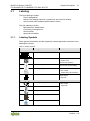
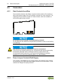
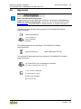
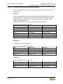
1.3 Symbols
Personal Injury!
Indicates a high-risk, imminently hazardous situation which, if not avoided, will
result in death or serious injury.
Personal Injury Caused by Electric Current!
Indicates a high-risk, imminently hazardous situation which, if not avoided, will
result in death or serious injury.
Personal Injury!
Indicates a moderate-risk, potentially hazardous situation which, if not avoided,
could result in death or serious injury.
Personal Injury!
Indicates a low-risk, potentially hazardous situation which, if not avoided, may
result in minor or moderate injury.
Damage to Property!
Indicates a potentially hazardous situation which, if not avoided, may result in
damage to property.
Damage to Property Caused by Electrostatic Discharge (ESD)!
Indicates a potentially hazardous situation which, if not avoided, may result in
damage to property.
Important Note!
Indicates a potential malfunction which, if not avoided, however, will not result in
damage to property.

10 Notes about this Documentation WAGO I/O System 750 XTR
750-364/040-010 FC MODBUS TCP M12 4G XTR
Manual
Version 1.1.0
Additional Information:
Refers to additional information which is not an integral part of this
documentation (e.g., the Internet).

WAGO I/O System 750 XTR Notes about this Documentation 11
750-364/040-010 FC MODBUS TCP M12 4G XTR
Manual
Version 1.1.0
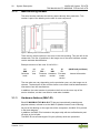
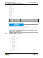
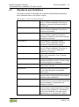
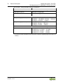
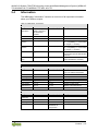
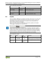
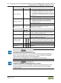
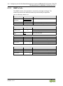
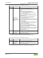
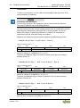
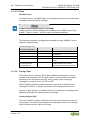
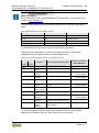
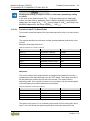
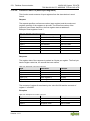
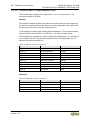
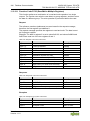
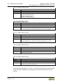
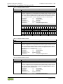
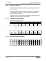
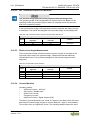
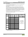
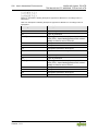
1.4 Number Notation
Table 1: Number Notation
Number Code
Example
Note
Decimal
100
Normal notation
Hexadecimal
0x64
C notation
Binary
'100'
'0110.0100'
In quotation marks, nibble separated
with dots (.)
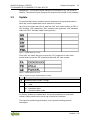
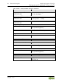
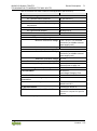
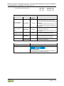
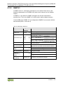
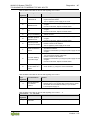
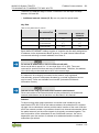
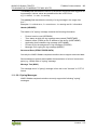
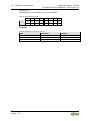
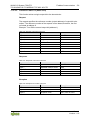
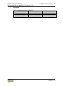
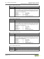
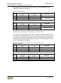
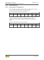
1.5 Font Conventions
Table 2: Font Conventions
Font Type
Indicates
italic
Names of paths and data files are marked in italic-type.
e.g.: C:\Program Files\WAGO Software
Menu
Menu items are marked in bold letters.
e.g.: Save
>
A greater-than sign between two names means the selection of a
menu item from a menu.
e.g.: File > New
Input
Designation of input or optional fields are marked in bold letters,
e.g.: Start of measurement range
“Value”
Input or selective values are marked in inverted commas.
e.g.: Enter the value “4 mA” under
Start of measurement range
.
[Button]
Pushbuttons in dialog boxes are marked with bold letters in square
brackets.
e.g.: [Input]
[Key]
Keys are marked with bold letters in square brackets.
e.g.: [F5]

12 Important Notes WAGO I/O System 750 XTR
750-364/040-010 FC MODBUS TCP M12 4G XTR
Manual
Version 1.1.0
2 Important Notes
This section includes an overall summary of the most important safety
requirements and notes that are mentioned in each individual section. To protect
your health and prevent damage to devices as well, it is imperative to read and
carefully follow the safety guidelines.
2.1 Legal Bases
2.1.1 Subject to Changes
WAGO Kontakttechnik GmbH & Co. KG reserves the right to provide for any
alterations or modifications. WAGO Kontakttechnik GmbH & Co. KG owns all
rights arising from the granting of patents or from the legal protection of utility
patents. Third-party products are always mentioned without any reference to
patent rights. Thus, the existence of such rights cannot be excluded.
2.1.2 Personnel Qualifications
All sequences implemented on WAGO I/O System 750 devices may only be
carried out by electrical specialists with sufficient knowledge in automation. The
specialists must be familiar with the current norms and guidelines for the devices
and automated environments.
All changes to the coupler or controller should always be carried out by qualified
personnel with sufficient skills in PLC programming.
2.1.3 Use of the 750 Series in Compliance with Underlying
Provisions
Fieldbus couplers, controllers and I/O modules of the modular WAGO I/O System
750 receive digital and analog signals from sensors and transmit them to
actuators or higher-level control systems. Using controllers, the signals can also
be (pre-) processed.
This product fulfills the requirements of protection type IP20 and is designed for
use in dry interior spaces. There is protection against finger injury and solid
impurities up to 12.5 mm diameter is assured; protection against water damage is
not ensured.
The product represents an open-type device. It may only be installed in
enclosures (tool-secured enclosures or operating rooms) which fulfil the listed
requirements specified in the safety instructions in chapter “Safety Advice
(Precautions)”. Use without additional protective measures in environments within
which dust, corrosive fumes, gases or ionized radiation can occur is considered
improper use.
The product is intended for installation in automation systems. It does not have
its own integrated separator. A suitable separator must therefore be created on
the plant side.

WAGO I/O System 750 XTR Important Notes 13
750-364/040-010 FC MODBUS TCP M12 4G XTR
Manual
Version 1.1.0
The operation of the product in residential areas without further measures is only
permitted if the product complies with the emission limits (interference emissions)
according to EN 61000-6-3.
Operating the product in home applications without further measures is only
permitted if it meets the emission limits (emissions of interference) according to
EN 61000-6-3. Please observe the installation regulations!
You will find the relevant information in the section “Device Description” >
“Standards and Guidelines” in the manual for the used product.
Appropriate housing (per 2014/34/EU) is required when operating the WAGO I/O
System 750 in hazardous environments. Please note that a prototype test
certificate must be obtained that confirms the correct installation of the system in
a housing or switch cabinet.
The implementation of safety functions such as EMERGENCY STOP or safety
door monitoring must only be performed by the F I/O modules within the modular
WAGO I/O System 750. Only these safe F I/O modules ensure functional safety
in accordance with the latest international standards. WAGO's interference-free
output modules can be controlled by the safety function.
2.1.4 Technical Condition of Specified Devices
The devices to be supplied ex works are equipped with hardware and software
configurations, which meet the individual application requirements. These
modules contain no parts that can be serviced or repaired by the user. The
following actions will result in the exclusion of liability on the part of WAGO
Kontakttechnik GmbH & Co. KG:
• Repairs,
• Changes to the hardware or software that are not described in the
operating instructions,
• Improper use of the components.
Further details are given in the contractual agreements. Please send your
request for modified and new hardware or software configurations directly to
WAGO Kontakttechnik GmbH & Co. KG.
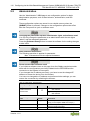
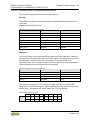
2.1.4.1 Disposal
2.1.4.1.1 Electrical and Electronic Equipment
Electrical and electronic equipment may not be disposed of
with household waste. This also applies to products without
this symbol.
Electrical and electronic equipment contain materials and substances that can be
harmful to the environment and health. Electrical and electronic equipment must

14 Important Notes WAGO I/O System 750 XTR
750-364/040-010 FC MODBUS TCP M12 4G XTR
Manual
Version 1.1.0
be disposed of properly after use.
WEEE 2012/19/EU applies throughout Europe. Directives and laws may vary
nationally.
Environmentally friendly disposal benefits health and protects
the environment from harmful substances in electrical and
electronic equipment.
• Observe national and local regulations for the disposal of electrical and
electronic equipment.
• Clear any data stored on the electrical and electronic equipment.
• Remove any added battery or memory card in the electrical and
electronic equipment.
• Have the electrical and electronic equipment sent to your local
collection point.
Improper disposal of electrical and electronic equipment can be harmful to the
environment and human health.
2.1.4.1.2 Packaging
Packaging contains materials that can be reused.
PPWD 94/62/EU and 2004/12/EU packaging guidelines apply throughout
Europe. Directives and laws may vary nationally.
Environmentally friendly disposal of the packaging protects the environment and
allows sustainable and efficient use of resources.
• Observe national and local regulations for the disposal of packaging.
• Dispose of packaging of all types that allows a high level of recovery,
reuse and recycling.
Improper disposal of packaging can be harmful to the environment and wastes
valuable resources.

WAGO I/O System 750 XTR Important Notes 15
750-364/040-010 FC MODBUS TCP M12 4G XTR
Manual
Version 1.1.0
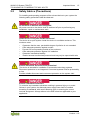
2.2 Safety Advice (Precautions)
For installing and operating purposes of the relevant device to your system the
following safety precautions shall be observed:
Do not work on devices while energized!
All power sources to the device shall be switched off prior to performing any
installation, repair or maintenance work.
Install device in only one suitable enclosure!
The device is an open system. Install the device in a suitable enclosure. This
enclosure must:
• Guarantee that the max. permissible degree of pollution is not exceeded.
• Offer adequate protection against contact.
• Prevent fire from spreading outside of the enclosure.
• Offer adequate protection against UV irradiation.
• Guarantee mechanical stability
• Restrict access to authorized personnel and may only be opened with tools
Ensure disconnect and overcurrent protection!
The device is intended for installation in automation technology systems.
Disconnect protection is not integrated. Connected systems must be protected by
a fuse.
Provide suitable disconnect and overcurrent protection on the system side!
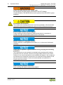
Ensure a standard connection!
To minimize any hazardous situations resulting in personal injury or to avoid
failures in your system, the data and power supply lines shall be installed
according to standards, with careful attention given to ensuring the correct
terminal assignment. Always adhere to the EMC directives applicable to your
application.

16 Important Notes WAGO I/O System 750 XTR
750-364/040-010 FC MODBUS TCP M12 4G XTR
Manual
Version 1.1.0
Power from SELV/PELV power supply only!
All field signals and field supplies connected to this XTR fieldbus
coupler/controller (750-364/040-010)
must be powered from SELV/PELV power
supply(s)!
Do not touch hot surfaces!
The surface of the housing can become hot during operation. If the device was
operated at high ambient temperatures, allow it to cool off before touching it.
Ensure proper contact with the DIN-rail!
Proper electrical contact between the DIN-rail and device is necessary to
maintain the EMC characteristics and function of the device.
Replace defective or damaged devices!
Replace defective or damaged device/module (e.g., in the event of deformed
contacts).
Protect the components against materials having seeping and insulating
properties!
The components are not resistant to materials having seeping and insulating
properties such as: aerosols, silicones and triglycerides (found in some hand
creams). If you cannot exclude that such materials will appear in the component
environment, then install the components in an enclosure being resistant to the
above-mentioned materials. Clean tools and materials are imperative for
handling devices/modules.
Clean only with permitted materials!
Clean housing and soiled contacts with propanol.

WAGO I/O System 750 XTR Important Notes 17
750-364/040-010 FC MODBUS TCP M12 4G XTR
Manual
Version 1.1.0
Do not use any contact spray!
Do not use any contact spray. The spray may impair contact area functionality in
connection with contamination.
Do not reverse the polarity of connection lines!
Avoid reverse polarity of data and power supply lines, as this may damage the
devices involved.
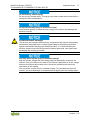
Avoid electrostatic discharge!
The devices are equipped with electronic components that may be destroyed by
electrostatic discharge when touched. Please observe the safety precautions
against electrostatic discharge per DIN EN 61340-5-1/-3. When handling the
devices, please ensure that environmental factors (personnel, work space and
packaging) are properly grounded.
Use only direct current (DC) for insulation testing!
Both the system voltage and field voltage side are capacitively coupled to the
DIN-rail. If an I/O module is mounted on the DIN-rail, application of an AC voltage
between the DIN-rail and at least one of these two potentials can lead to the
destruction of the module.
Use only direct current (DC) for insulation testing. To avoid destroying the I/O
module, you must discharge it completely before applying the test voltage again.

18 Important Notes WAGO I/O System 750 XTR
750-364/040-010 FC MODBUS TCP M12 4G XTR
Manual
Version 1.1.0
2.3 Special Use Conditions for ETHERNET Devices
If not otherwise specified, ETHERNET devices are intended for use on local
networks. Please note the following when using ETHERNET devices in your
system:
• Do not connect control components and control networks directly to an
open network such as the Internet or an office network. WAGO
recommends putting control components and control networks behind a
firewall.
• In the control components (e.g., for WAGO I/-CHECK and CODESYS)
close all ports and services not required by your application to minimize the
risk of cyber attacks and to enhance cyber security.
Only open ports and services during commissioning and/or configuration.
• Limit physical and electronic access to all automation components to
authorized personnel only.
• Change the default passwords before first use! This will reduce the risk of
unauthorized access to your system.
• Regularly change the passwords used! This will reduce the risk of
unauthorized access to your system.
• If remote access to control components and control networks is required,
use a Virtual Private Network (VPN).
• Regularly perform threat analyses. You can check whether the measures
taken meet your security requirements.
• Use “defense-in-depth” mechanisms in your system's security configuration
to restrict the access to and control of individual products and networks.

WAGO I/O System 750 XTR System Description 19
750-364/040-010 FC MODBUS TCP M12 4G XTR
Manual
Version 1.1.0
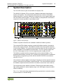
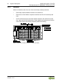
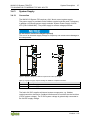
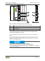
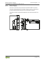
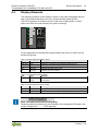
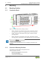
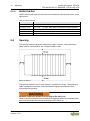
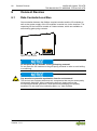
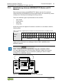
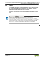
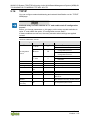
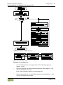
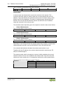
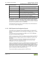
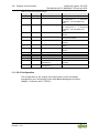
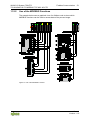
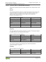
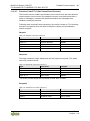
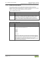
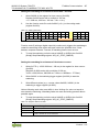
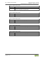
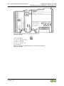
3 System Description
The 750 XTR Series is part of the WAGO I/O System 750.
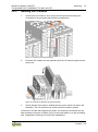
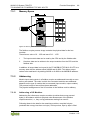
The WAGO I/O System 750 is a modular, fieldbus-independent input/output
system (I/O system). The configuration described here consists of a fieldbus
coupler/controller (1) and the modular I/O modules (2) for any signal shapes that
form the fieldbus node together. The end module (3) completes the node and is
required for correct operation of the fieldbus node.
Figure 1: Fieldbus Node (Example)
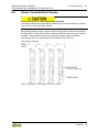
Fieldbus couplers/controllers are available for different fieldbus systems.
The extended ECO fieldbus couplers contain the fieldbus interface, electronics
and a power supply terminal. The fieldbus interface forms the physical interface
to the relevant fieldbus. The electronics process the data of the bus modules and
make it available for the fieldbus communication. The 24 V system supply and
the 24 V field supply are fed in via the integrated power supply terminal.
The fieldbus coupler/controller communicates via the relevant fieldbus. The
programmable fieldbus controller (PFC) enables the implementation of additional
PLC functions. Programming is done with the WAGO-I/O-PRO in accordance
with IEC 61131-3.
I/O modules for diverse digital and analog I/O signals as well as special functions
can be connected to the fieldbus coupler/controller. The communication between
the fieldbus coupler/controller and the I/O modules is carried out via a local bus.
The components of the WAGO I/O System 750 have clear termination points,
light emitting diodes for status display, plug-in mini WSB tags and group marker
cards for labeling.
The 1, 2 or 3 wire technology supplemented by a ground wire connection allows
for direct sensor or actuator wiring.

20 System Description WAGO I/O System 750 XTR
750-364/040-010 FC MODBUS TCP M12 4G XTR
Manual
Version 1.1.0
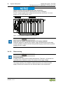
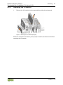
The distinctiveness of the 750 XTR Series lies in its area of application in
extreme environmental conditions. It is extremely temperature-resistant, immune
to interference, as well as insensitive to vibrations and impulse voltages.
The components of the 750 XTR Series are easily recognizable by their dark-
gray housing color.
La pagina si sta caricando...
La pagina si sta caricando...
La pagina si sta caricando...
La pagina si sta caricando...
La pagina si sta caricando...
La pagina si sta caricando...
La pagina si sta caricando...
La pagina si sta caricando...
La pagina si sta caricando...
La pagina si sta caricando...
La pagina si sta caricando...
La pagina si sta caricando...
La pagina si sta caricando...
La pagina si sta caricando...
La pagina si sta caricando...
La pagina si sta caricando...
La pagina si sta caricando...
La pagina si sta caricando...
La pagina si sta caricando...
La pagina si sta caricando...
La pagina si sta caricando...
La pagina si sta caricando...
La pagina si sta caricando...
La pagina si sta caricando...
La pagina si sta caricando...
La pagina si sta caricando...
La pagina si sta caricando...
La pagina si sta caricando...
La pagina si sta caricando...
La pagina si sta caricando...
La pagina si sta caricando...
La pagina si sta caricando...
La pagina si sta caricando...
La pagina si sta caricando...
La pagina si sta caricando...
La pagina si sta caricando...
La pagina si sta caricando...
La pagina si sta caricando...
La pagina si sta caricando...
La pagina si sta caricando...
La pagina si sta caricando...
La pagina si sta caricando...
La pagina si sta caricando...
La pagina si sta caricando...
La pagina si sta caricando...
La pagina si sta caricando...
La pagina si sta caricando...
La pagina si sta caricando...
La pagina si sta caricando...
La pagina si sta caricando...
La pagina si sta caricando...
La pagina si sta caricando...
La pagina si sta caricando...
La pagina si sta caricando...
La pagina si sta caricando...
La pagina si sta caricando...
La pagina si sta caricando...
La pagina si sta caricando...
La pagina si sta caricando...
La pagina si sta caricando...
La pagina si sta caricando...
La pagina si sta caricando...
La pagina si sta caricando...
La pagina si sta caricando...
La pagina si sta caricando...
La pagina si sta caricando...
La pagina si sta caricando...
La pagina si sta caricando...
La pagina si sta caricando...
La pagina si sta caricando...
La pagina si sta caricando...
La pagina si sta caricando...
La pagina si sta caricando...
La pagina si sta caricando...
La pagina si sta caricando...
La pagina si sta caricando...
La pagina si sta caricando...
La pagina si sta caricando...
La pagina si sta caricando...
La pagina si sta caricando...
La pagina si sta caricando...
La pagina si sta caricando...
La pagina si sta caricando...
La pagina si sta caricando...
La pagina si sta caricando...
La pagina si sta caricando...
La pagina si sta caricando...
La pagina si sta caricando...
La pagina si sta caricando...
La pagina si sta caricando...
La pagina si sta caricando...
La pagina si sta caricando...
La pagina si sta caricando...
La pagina si sta caricando...
La pagina si sta caricando...
La pagina si sta caricando...
La pagina si sta caricando...
La pagina si sta caricando...
La pagina si sta caricando...
La pagina si sta caricando...
La pagina si sta caricando...
La pagina si sta caricando...
La pagina si sta caricando...
La pagina si sta caricando...
La pagina si sta caricando...
La pagina si sta caricando...
La pagina si sta caricando...
La pagina si sta caricando...
La pagina si sta caricando...
La pagina si sta caricando...
La pagina si sta caricando...
La pagina si sta caricando...
La pagina si sta caricando...
La pagina si sta caricando...
La pagina si sta caricando...
La pagina si sta caricando...
La pagina si sta caricando...
La pagina si sta caricando...
La pagina si sta caricando...
La pagina si sta caricando...
La pagina si sta caricando...
La pagina si sta caricando...
La pagina si sta caricando...
La pagina si sta caricando...
La pagina si sta caricando...
La pagina si sta caricando...
La pagina si sta caricando...
La pagina si sta caricando...
La pagina si sta caricando...
La pagina si sta caricando...
La pagina si sta caricando...
La pagina si sta caricando...
La pagina si sta caricando...
La pagina si sta caricando...
La pagina si sta caricando...
La pagina si sta caricando...
La pagina si sta caricando...
La pagina si sta caricando...
La pagina si sta caricando...
La pagina si sta caricando...
La pagina si sta caricando...
La pagina si sta caricando...
La pagina si sta caricando...
La pagina si sta caricando...
La pagina si sta caricando...
La pagina si sta caricando...
La pagina si sta caricando...
La pagina si sta caricando...
La pagina si sta caricando...
La pagina si sta caricando...
La pagina si sta caricando...
La pagina si sta caricando...
La pagina si sta caricando...
La pagina si sta caricando...
La pagina si sta caricando...
La pagina si sta caricando...
La pagina si sta caricando...
La pagina si sta caricando...
La pagina si sta caricando...
La pagina si sta caricando...
La pagina si sta caricando...
La pagina si sta caricando...
La pagina si sta caricando...
La pagina si sta caricando...
La pagina si sta caricando...
La pagina si sta caricando...
La pagina si sta caricando...
La pagina si sta caricando...
La pagina si sta caricando...
La pagina si sta caricando...
La pagina si sta caricando...
La pagina si sta caricando...
La pagina si sta caricando...
La pagina si sta caricando...
La pagina si sta caricando...
La pagina si sta caricando...
La pagina si sta caricando...
La pagina si sta caricando...
La pagina si sta caricando...
La pagina si sta caricando...
La pagina si sta caricando...
La pagina si sta caricando...
La pagina si sta caricando...
La pagina si sta caricando...
La pagina si sta caricando...
La pagina si sta caricando...
La pagina si sta caricando...
La pagina si sta caricando...
La pagina si sta caricando...
La pagina si sta caricando...
La pagina si sta caricando...
La pagina si sta caricando...
La pagina si sta caricando...
La pagina si sta caricando...
La pagina si sta caricando...
La pagina si sta caricando...
La pagina si sta caricando...
La pagina si sta caricando...
La pagina si sta caricando...
La pagina si sta caricando...
La pagina si sta caricando...
La pagina si sta caricando...
La pagina si sta caricando...
La pagina si sta caricando...
La pagina si sta caricando...
La pagina si sta caricando...
La pagina si sta caricando...
La pagina si sta caricando...
La pagina si sta caricando...
La pagina si sta caricando...
La pagina si sta caricando...
La pagina si sta caricando...
La pagina si sta caricando...
La pagina si sta caricando...
La pagina si sta caricando...
La pagina si sta caricando...
La pagina si sta caricando...
La pagina si sta caricando...
La pagina si sta caricando...
La pagina si sta caricando...
La pagina si sta caricando...
La pagina si sta caricando...
La pagina si sta caricando...
La pagina si sta caricando...
-
 1
1
-
 2
2
-
 3
3
-
 4
4
-
 5
5
-
 6
6
-
 7
7
-
 8
8
-
 9
9
-
 10
10
-
 11
11
-
 12
12
-
 13
13
-
 14
14
-
 15
15
-
 16
16
-
 17
17
-
 18
18
-
 19
19
-
 20
20
-
 21
21
-
 22
22
-
 23
23
-
 24
24
-
 25
25
-
 26
26
-
 27
27
-
 28
28
-
 29
29
-
 30
30
-
 31
31
-
 32
32
-
 33
33
-
 34
34
-
 35
35
-
 36
36
-
 37
37
-
 38
38
-
 39
39
-
 40
40
-
 41
41
-
 42
42
-
 43
43
-
 44
44
-
 45
45
-
 46
46
-
 47
47
-
 48
48
-
 49
49
-
 50
50
-
 51
51
-
 52
52
-
 53
53
-
 54
54
-
 55
55
-
 56
56
-
 57
57
-
 58
58
-
 59
59
-
 60
60
-
 61
61
-
 62
62
-
 63
63
-
 64
64
-
 65
65
-
 66
66
-
 67
67
-
 68
68
-
 69
69
-
 70
70
-
 71
71
-
 72
72
-
 73
73
-
 74
74
-
 75
75
-
 76
76
-
 77
77
-
 78
78
-
 79
79
-
 80
80
-
 81
81
-
 82
82
-
 83
83
-
 84
84
-
 85
85
-
 86
86
-
 87
87
-
 88
88
-
 89
89
-
 90
90
-
 91
91
-
 92
92
-
 93
93
-
 94
94
-
 95
95
-
 96
96
-
 97
97
-
 98
98
-
 99
99
-
 100
100
-
 101
101
-
 102
102
-
 103
103
-
 104
104
-
 105
105
-
 106
106
-
 107
107
-
 108
108
-
 109
109
-
 110
110
-
 111
111
-
 112
112
-
 113
113
-
 114
114
-
 115
115
-
 116
116
-
 117
117
-
 118
118
-
 119
119
-
 120
120
-
 121
121
-
 122
122
-
 123
123
-
 124
124
-
 125
125
-
 126
126
-
 127
127
-
 128
128
-
 129
129
-
 130
130
-
 131
131
-
 132
132
-
 133
133
-
 134
134
-
 135
135
-
 136
136
-
 137
137
-
 138
138
-
 139
139
-
 140
140
-
 141
141
-
 142
142
-
 143
143
-
 144
144
-
 145
145
-
 146
146
-
 147
147
-
 148
148
-
 149
149
-
 150
150
-
 151
151
-
 152
152
-
 153
153
-
 154
154
-
 155
155
-
 156
156
-
 157
157
-
 158
158
-
 159
159
-
 160
160
-
 161
161
-
 162
162
-
 163
163
-
 164
164
-
 165
165
-
 166
166
-
 167
167
-
 168
168
-
 169
169
-
 170
170
-
 171
171
-
 172
172
-
 173
173
-
 174
174
-
 175
175
-
 176
176
-
 177
177
-
 178
178
-
 179
179
-
 180
180
-
 181
181
-
 182
182
-
 183
183
-
 184
184
-
 185
185
-
 186
186
-
 187
187
-
 188
188
-
 189
189
-
 190
190
-
 191
191
-
 192
192
-
 193
193
-
 194
194
-
 195
195
-
 196
196
-
 197
197
-
 198
198
-
 199
199
-
 200
200
-
 201
201
-
 202
202
-
 203
203
-
 204
204
-
 205
205
-
 206
206
-
 207
207
-
 208
208
-
 209
209
-
 210
210
-
 211
211
-
 212
212
-
 213
213
-
 214
214
-
 215
215
-
 216
216
-
 217
217
-
 218
218
-
 219
219
-
 220
220
-
 221
221
-
 222
222
-
 223
223
-
 224
224
-
 225
225
-
 226
226
-
 227
227
-
 228
228
-
 229
229
-
 230
230
-
 231
231
-
 232
232
-
 233
233
-
 234
234
-
 235
235
-
 236
236
-
 237
237
-
 238
238
-
 239
239
-
 240
240
-
 241
241
-
 242
242
-
 243
243
-
 244
244


WAGO Fieldbus Coupler Modbus TCP M12 Manuale utente
- Categoria
- Networking
- Tipo
- Manuale utente
in altre lingue
Documenti correlati
Altri documenti
-
Hach SC200 Basic User Manual
-
 West Control Solutions Rail line MODTCP Manuale utente
-
BEL LET480 Guida d'installazione
-
Dynisco SPXD Manuale utente
-
Advantech ADAM-5000/TCP Series Manuale utente
-
SICK Flexi Gateway GPNT1 Expansion module - gateway Istruzioni per l'uso
-
 Orolia PRISMA Compliance Manuale utente
-
ABB RED650 Applications Manual
-
Trox FAM-RADIODUCT Guida d'installazione
-
ABB 266P Series Short Form Instruction Manual

