
Pos: 2 /D ok ument ati on al lg em ein/E inb and /Ei nban d F ro ntsei te - Han dbuc h; C I 20 17; mit Do cVar ia ble n (St an dard) @ 28\mod_1486477502910_0.docx @ 405388 @ @ 1
Manual
WAGO-I/O-SYSTEM 750 XTR
750-880/040-00x
Controller ETHERNET G3 SD XTR
Controller ETHERNET, 3. Generation, SD Card Slot,
Extreme
Version 1.4.0
Pos: 3 /A lle Ser ien ( All ge mein e M odul e)/ Rec htlic h es, A llg emei nes /Im pre ssu m f ür St and ard han dbüc her - al lg. Ang abe n, A nschr iften, Telefo nnum mern un d E-Mail- Adres sen @ 3\mod_1219151118203_21.docx @ 21060 @ @ 1

2 WAGO-I/O-SYSTEM 750 XTR
750-880/040-00x Controller ETHERNET G3 SD XTR
Manual
Version 1.4.0
© 2019 WAGO Kontakttechnik GmbH & Co. KG
All rights reserved.
WAGO Kontakttechnik GmbH & Co. KG
Hansastraße 27
D-32423 Minden
Phone: +49 (0) 571/8 87 – 0
Fax: +49 (0) 571/8 87 – 1 69
Web: www.wago.com
Technical Support
Phone: +49 (0) 571/8 87 – 4 45 55
Fax: +49 (0) 571/8 87 – 84 45 55
Every conceivable measure has been taken to ensure the accuracy and
completeness of this documentation. However, as errors can never be fully
excluded, we always appreciate any information or suggestions for improving the
documentation.
We wish to point out that the software and hardware terms as well as the
trademarks of companies used and/or mentioned in the present manual are
generally protected by trademark or patent.
WAGO is a registered trademark of WAGO Verwaltungsgesellschaft mbH.
=== Ende der Lis te f ür T e xtmar ke Ei nb and _vor ne = ==

WAGO-I/O-SYSTEM 750 XTR Table of Contents 3
750-880/040-00x Controller ETHERNET G3 SD XTR
Manual
Version 1.4.0
Pos: 5 /D ok ument ati on al lg em ein/V erz eic hni sse /Inh alts ver zei chni s - Ü bersc hrift oG und Ver zeich nis @ 3\mod_1219151230875_21.docx @ 21063 @ @ 1
Table of Contents
1 Notes about this Documentation ........................................................... 12
1.1 Validity of this Documentation............................................................... 12
1.2 Copyright .............................................................................................. 12
1.3 Symbols ............................................................................................... 13
1.4 Number Notation .................................................................................. 14
1.5 Font Conventions ................................................................................. 14
2 Important Notes ...................................................................................... 15
2.1 Legal Bases .......................................................................................... 15
2.1.1 Subject to Changes .......................................................................... 15
2.1.2 Personnel Qualifications .................................................................. 15
2.1.3 Use of the 750 Series in Compliance with Underlying Provisions ..... 15
2.1.4 Technical Condition of Specified Devices......................................... 16
2.1.4.1 Disposal ...................................................................................... 16
2.1.4.1.1 Electrical and Electronic Equipment ........................................ 16
2.1.4.1.2 Packaging ............................................................................... 17
2.2 Safety Advice (Precautions) ................................................................. 18
2.3 Special Use Conditions for ETHERNET Devices .................................. 21
3 System Description ................................................................................. 22
3.1 Labeling ................................................................................................ 24
3.1.1 Labeling Symbols ............................................................................. 24
3.1.2 Manufacturing Number ..................................................................... 25
3.1.3 Hardware Address (MAC-ID) ........................................................... 25
3.2 Update .................................................................................................. 26
3.3 Storage, Assembly and Transport ........................................................ 27
3.4 Assembly Guidelines/Standards ........................................................... 27
3.5 Power Supply ....................................................................................... 28
3.5.1 Overcurrent Protection ..................................................................... 28
3.5.2 Isolation ........................................................................................... 29
3.5.3 System Supply ................................................................................. 30
3.5.3.1 Connection .................................................................................. 30
3.5.3.2 Dimensioning ............................................................................... 31
3.5.4 Field Supply ..................................................................................... 33
3.5.4.1 Connection .................................................................................. 33
3.5.4.2 Fusing via Power Supply Module ................................................. 35
3.5.4.3 Fusing External ........................................................................... 37
3.5.5 Power Supply for Mixed Operation ................................................... 39
3.5.6 Supplementary Power Supply Regulations ...................................... 40
3.5.7 Supply Example ............................................................................... 42
3.5.8 Power Supply Units .......................................................................... 43
3.6 Grounding............................................................................................. 44
3.6.1 Grounding the DIN Rail .................................................................... 44
3.6.1.1 Framework Assembly .................................................................. 44
3.6.1.2 Insulated Assembly ..................................................................... 44
3.6.2 Grounding Function ......................................................................... 45
3.7 Shielding .............................................................................................. 46
3.7.1 General ............................................................................................ 46

4 Table of Contents WAGO-I/O-SYSTEM 750 XTR
750-880/040-00x Controller ETHERNET G3 SD XTR
Manual
Version 1.4.0
3.7.2 Fieldbus Cables ............................................................................... 46
3.7.3 Shielded Signal Lines....................................................................... 47
3.7.4 WAGO Shield Connecting System ................................................... 47
4 Device Description .................................................................................. 48
4.1 View ..................................................................................................... 51
4.2 Connectors ........................................................................................... 53
4.2.1 Device Supply .................................................................................. 53
4.2.2 Fieldbus Connection ........................................................................ 53
4.3 Display Elements .................................................................................. 55
4.4 Operating Elements .............................................................................. 56
4.4.1 Service Interface .............................................................................. 56
4.4.2 Mode Selector Switch ...................................................................... 57
4.4.3 Address Selection Switch ................................................................. 59
4.4.4 Memory Card Slot ............................................................................ 60
4.4.4.1 Inserting a Memory Card ............................................................. 61
4.4.4.2 Removing the Memory Card ........................................................ 61
4.5 Technical Data ..................................................................................... 62
4.5.1 Device Data ..................................................................................... 62
4.5.2 System Data .................................................................................... 62
4.5.3 Supply .............................................................................................. 63
4.5.4 Fieldbus MODBUS/TCP ................................................................... 63
4.5.5 Accessories ..................................................................................... 64
4.5.6 Connection Type .............................................................................. 64
4.5.7 Mechanical Conditions ..................................................................... 64
4.5.8 Climatic Environmental Conditions ................................................... 65
4.6 Approvals ............................................................................................. 66
4.7 Standards and Guidelines .................................................................... 67
5 Mounting .................................................................................................. 74
5.1 Installation Position ............................................................................... 74
5.2 Overall Configuration ............................................................................ 76
5.3 Mounting onto Carrier Rail .................................................................... 77
5.3.1 Carrier Rail Properties ...................................................................... 77
5.3.2 WAGO DIN Rails ............................................................................. 78
5.4 Spacing ................................................................................................ 78
5.5 Mounting Sequence .............................................................................. 79
5.6 Inserting and Removing Devices .......................................................... 80
5.6.1 Inserting the Fieldbus Coupler/Controller ......................................... 80
5.6.2 Removing the Fieldbus Coupler/Controller ....................................... 81
5.6.3 Inserting the I/O Module ................................................................... 81
5.6.4 Removing the I/O Module ................................................................ 82
6 Connect Devices ..................................................................................... 83
6.1 Data Contacts/Local Bus ...................................................................... 83
6.2 Power Contacts/Field Supply ................................................................ 84
6.3 Connecting a Conductor to the CAGE CLAMP
®
................................... 85
7 Function Description .............................................................................. 86
7.1 Operating System ................................................................................. 86
7.1.1 Start-up ............................................................................................ 86

WAGO-I/O-SYSTEM 750 XTR Table of Contents 5
750-880/040-00x Controller ETHERNET G3 SD XTR
Manual
Version 1.4.0
7.1.2 Application Program Cycle ............................................................... 86
7.2 Process Data Architecture .................................................................... 88
7.2.1 Basic Structure................................................................................. 88
7.2.2 Example of an Input Process Image ................................................. 90
7.2.3 Example of an Output Data Process Image ..................................... 91
7.2.4 Process Data MODBUS/TCP and EtherNet/IP ................................. 92
7.3 Data Exchange ..................................................................................... 93
7.3.1 Memory Areas.................................................................................. 94
7.3.2 Addressing ....................................................................................... 97
7.3.2.1 Addressing of I/O Modules .......................................................... 98
7.3.2.2 IEC-61131-3 Address Areas ........................................................ 99
7.3.2.3 Absolute Addressing .................................................................. 100
7.3.3 Data Exchange between MODBUS/TCP Master and I/O Modules . 101
7.3.4 Data Exchange between EtherNet/IP Master and I/O Modules ...... 103
7.3.5 Data Exchange between PLC Function (CPU) and I/O Modules .... 104
7.3.6 Data Exchange between Master and PLC Function (CPU) ............ 105
7.3.6.1 Example of MODBUS/TCP Master and PLC Function (CPU) .... 105
7.3.7 Application Example ...................................................................... 107
7.4 Memory Card Function ....................................................................... 108
7.4.1 Project Copying and Automatic System Start ................................. 109
7.4.2 Back-up Function (Storing Device-internal Data and Settings
on the Memory Card) ..................................................................... 111
7.4.3 Restore Function (Loading Device-internal Data and Settings
from the Memory Card) .................................................................. 112
7.4.4 Inserting a Memory Card During Operation .................................... 115
7.4.5 Removing the Memory Card During Operation............................... 116
7.4.6 Saving WAGO-I/O-PRO project to Memory Card ........................... 117
7.4.7 FTP Network Access to the File System of the Memory Card ........ 120
7.4.8 Access to Web Pages in the File System of the Memory Card ....... 121
7.4.9 Directory Structure ......................................................................... 122
8 Commissioning ..................................................................................... 123
8.1 Connecting Client PC and Fieldbus Nodes ......................................... 124
8.2 Assigning the IP Address to the Fieldbus Node .................................. 124
8.2.1 Assigning IP Address via Address Selection Switch ....................... 125
8.2.2 Assigning IP Address via DHCP .................................................... 127
8.2.2.1 Enable DHCP ............................................................................ 128
8.2.2.2 Assigning the IP address permanently by option “use IP
from EEPROM“ ......................................................................... 128
8.2.3 Assigning IP Address via “WAGO Ethernet Settings” ..................... 130
8.2.4 Assigning the IP Address with a PLC program ............................... 132
8.2.5 Assigning the IP Address with a BootP Server ............................... 132
8.2.5.1 Note MAC ID ............................................................................. 133
8.2.5.2 Determining IP addresses ......................................................... 134
8.2.5.3 Assigning the IP address permanently by option “use IP
from EEPROM“ ......................................................................... 136
8.2.5.4 Reasons for Failed IP Address Assignment ............................... 138
8.3 Testing the Function of the Fieldbus Node.......................................... 139
8.4 Preparing the Flash File System ......................................................... 140
8.5 Synchronizing the Clock Time ............................................................ 141

6 Table of Contents WAGO-I/O-SYSTEM 750 XTR
750-880/040-00x Controller ETHERNET G3 SD XTR
Manual
Version 1.4.0
8.6 Restoring Factory Settings ................................................................. 143
9 Programming the PFC Using WAGO-I/O-PRO..................................... 144
9.1 Configuring the Controller using the I/O Configurator ......................... 147
9.1.1 Configuration using the “io-config.xml” File .................................... 149
9.2 ETHERNET Libraries for WAGO-I/O-PRO.......................................... 151
9.3 Functional Restrictions and Limits ...................................................... 152
9.4 General Information about IEC Tasks ................................................. 155
9.4.1 IEC Task Sequence ....................................................................... 157
9.4.2 Overview of Most Important Task Priorities .................................... 157
9.5 System Events ................................................................................... 159
9.5.1 Enabling/Disabling System Events ................................................. 159
9.6 Transfer the IEC Program to the Fieldbus Controller .......................... 160
9.6.1 Transfer via Serial Service Port ...................................................... 161
9.6.2 Transfer via Fieldbus and ETHERNET ........................................... 164
10 Configuring via the Web-Based Management System (WBM) ........... 166
10.1 Information ......................................................................................... 169
10.2 Ethernet .............................................................................................. 171
10.3 TCP/IP ................................................................................................ 174
10.4 Port..................................................................................................... 176
10.5 SNMP ................................................................................................. 178
10.5.1 SNMP V1/V2c ................................................................................ 179
10.5.2 SNMP V3 ....................................................................................... 181
10.6 Watchdog ........................................................................................... 183
10.7 Clock .................................................................................................. 185
10.8 Security .............................................................................................. 188
10.9 MODBUS............................................................................................ 191
10.10 EtherNet/IP ......................................................................................... 193
10.11 PLC Info ............................................................................................. 195
10.12 PLC .................................................................................................... 196
10.13 Features ............................................................................................. 201
10.14 I/O Config ........................................................................................... 202
10.15 Disk Info ............................................................................................. 205
10.16 SD Card ............................................................................................. 206
10.17 Backup & Restore ............................................................................... 208
10.18 WebVisu ............................................................................................. 212
11 Diagnostics............................................................................................ 214
11.1 LED Signaling ..................................................................................... 214
11.1.1 Evaluating Fieldbus Status ............................................................. 215
11.1.2 Evaluating Node Status – I/O LED (Blink Code Table) ................... 216
11.1.2.1 USR LED ................................................................................... 226
11.1.3 Evaluating Memory Card Status ..................................................... 226
11.1.4 Evaluating Power Supply Status .................................................... 226
11.2 Fault Behavior .................................................................................... 227
11.2.1 Loss of Fieldbus ............................................................................. 227
11.2.2 Local Bus Failure ........................................................................... 228
12 Fieldbus Communication ..................................................................... 229
12.1 Implemented Protocols ....................................................................... 229

WAGO-I/O-SYSTEM 750 XTR Table of Contents 7
750-880/040-00x Controller ETHERNET G3 SD XTR
Manual
Version 1.4.0
12.1.1 Communication Protocols .............................................................. 229
12.1.1.1 IP (Internet Protocol) ................................................................. 229
12.1.1.2 TCP (Transmission Control Protocol) ........................................ 234
12.1.1.3 UDP (User Datagram Protocol) ................................................. 235
12.1.2 Configuration and Diagnostics Protocols ........................................ 235
12.1.2.1 BootP (Bootstrap Protocol) ........................................................ 235
12.1.2.2 DHCP (Dynamic Host Configuration Protocol) ........................... 236
12.1.2.3 HTTP (Hypertext Transfer Protocol) .......................................... 239
12.1.2.4 DNS (Domain Name Systems) .................................................. 239
12.1.2.5 SNTP-Client (Simple Network Time Protocol) ............................ 239
12.1.2.6 FTP-Server (File Transfer Protocol) ........................................... 240
12.1.2.7 SNMP (Simple Network Management Protocol) ........................ 241
12.1.2.7.1 MIB II Description .................................................................. 241
12.1.2.7.2 Traps .................................................................................... 242
12.1.3 Application Protocols...................................................................... 242
12.2 Modbus Functions .............................................................................. 243
12.2.1 General .......................................................................................... 243
12.2.2 Use of the MODBUS Functions ...................................................... 246
12.2.3 Description of the MODBUS Functions .......................................... 247
12.2.3.1 Function Code FC1 (Read Coils) ............................................... 248
12.2.3.2 Function Code FC2 (Read Discrete Inputs) ............................... 249
12.2.3.3 Function Code FC3 (Read Multiple Registers) ........................... 250
12.2.3.4 Function Code FC4 (Read Input Registers) ............................... 251
12.2.3.5 Function Code FC5 (Write Coil) ................................................. 252
12.2.3.6 Function Code FC6 (Write Single Register) ............................... 253
12.2.3.7 Function Code FC11 (Get Comm Event Counter) ..................... 254
12.2.3.8 Function Code FC15 (Write Multiple Coils) ................................ 255
12.2.3.9 Function Code FC16 (Write Multiple Registers) ......................... 257
12.2.3.10 Function Code FC22 (Mask Write Register) .............................. 258
12.2.3.11 Function Code FC23 (Read/Write Multiple Registers) ............... 259
12.2.4 MODBUS Register Mapping .......................................................... 260
12.2.5 MODBUS Registers ....................................................................... 263
12.2.5.1 Accessing Register Values ........................................................ 264
12.2.5.2 Watchdog Registers .................................................................. 264
12.2.5.3 Modbus
Watchdog Register ....................................................... 265
12.2.5.4 Diagnostic Registers .................................................................. 269
12.2.5.5 Configuration Registers ............................................................. 270
12.2.5.6 Firmware Information Registers ................................................. 275
12.2.5.7 Constant Registers .................................................................... 277
12.3 EtherNet/IP (Ethernet/Industrial Protocol) ........................................... 279
12.3.1 General .......................................................................................... 279
12.3.2 Protocol overview in the OSI model ............................................... 280
12.3.3 Characteristics of the EtherNet/IP Protocol Software ..................... 281
12.3.4 EDS File......................................................................................... 281
12.3.5 Object Model .................................................................................. 282
12.3.5.1 General ..................................................................................... 282
12.3.5.2 Class Overview ......................................................................... 283
12.3.5.3 Explanation of the Table Headings in the Object Descriptions ... 285
12.3.5.4 Identity (01
hex
) ........................................................................... 285
12.3.5.5 Message Router (02
hex
) ............................................................ 287

8 Table of Contents WAGO-I/O-SYSTEM 750 XTR
750-880/040-00x Controller ETHERNET G3 SD XTR
Manual
Version 1.4.0
12.3.5.6 Assembly Object (04
hex
) ............................................................ 288
12.3.5.7 Connection (05
hex
) ..................................................................... 293
12.3.5.8 Connection Manager (06
hex
) ...................................................... 294
12.3.5.9 Port Class (F4
hex
) ...................................................................... 294
12.3.5.10 TCP/IP Interface (F5
hex
) ............................................................ 296
12.3.5.11 Ethernet Link (F6
hex
) ................................................................. 298
12.3.5.12 Coupler/Controller Configuration (64
hex
).................................... 302
12.3.5.13 Discrete Input Point (65
hex
) ....................................................... 304
12.3.5.14 Discrete Input Point Extended 1 (69
hex
) .................................... 305
12.3.5.15 Discrete Input Point Extended 2 (6D
hex
) .................................... 306
12.3.5.16 Discrete Input Point Extended 3 (71
hex
) .................................... 307
12.3.5.17 Discrete Output Point (66
hex
) ..................................................... 308
12.3.5.18 Discrete Output Point Extended 1 (6A
hex
) ................................. 309
12.3.5.19 Discrete Output Point Extended 2 (6E
hex
) ................................. 310
12.3.5.20 Discrete Output Point Extended 3 (72
hex
) .................................. 311
12.3.5.21 Analog Input Point (67
hex
) ......................................................... 312
12.3.5.22 Analog Input Point Extended 1 (6B
hex
) ...................................... 313
12.3.5.23 Analog Input Point Extended 2 (6F
hex
) ...................................... 314
12.3.5.24 Analog Input Point Extended 3 (73
hex
) ...................................... 315
12.3.5.25 Analog Output Point (68
hex
) ...................................................... 316
12.3.5.26 Analog Output Point Extended 1 (6C
hex
) ................................... 317
12.3.5.27 Analog Output Point Extended 2 (70
hex
) .................................... 318
12.3.5.28 Analog Output Point Extended 3 (74
hex
) .................................... 319
12.3.5.29 Module Configuration (80
hex
) ..................................................... 320
12.3.5.30 Module Configuration Extended (81
hex
) ..................................... 321
12.3.5.31 Input Fieldbus Variable USINT (A0
hex
) ...................................... 322
12.3.5.32 Input Fieldbus Variable USINT Extended 1 (A1
hex
) ................... 323
12.3.5.33 Input Fieldbus Variable USINT Extended 2 (A2
hex
) ................... 324
12.3.5.34 Output Fieldbus Variable USINT (A3
hex
) ................................... 325
12.3.5.35 Output Fieldbus Variable USINT Extended 1 (A4
hex
) ................ 326
12.3.5.36 Output Fieldbus Variable USINT Extended 2 (A5
hex
) ................ 327
12.3.5.37 Input Fieldbus Variable UINT (A6
hex
) ........................................ 328
12.3.5.38 Input Fieldbus Variable UINT Extended 1 (A7
hex
) ...................... 329
12.3.5.39 Output Fieldbus Variable UINT (A8
hex
) ...................................... 330
12.3.5.40 Output Fieldbus Variable UINT Extended 1 (A9
hex
) ................... 331
12.3.5.41 Input Fieldbus Variable UDINT (AA
hex
) ..................................... 332
12.3.5.42 Input Fieldbus Variable UDINT Offset (AB
hex
) ........................... 333
12.3.5.43 Output Fieldbus Variable UDINT (AC
hex
)................................... 334
12.3.5.44 Output Fieldbus Variable UDINT Offset (AD
hex
) ........................ 335
13 I/O Modules............................................................................................ 336
13.1 Overview ............................................................................................ 336
13.2 Process Data Architecture for Modbus TCP ....................................... 337
13.2.1 Digital Input Modules...................................................................... 338
13.2.1.1 2-Channel Digital Input Modules ................................................ 338
13.2.1.2 8-Channel Digital Input Modules ................................................ 338
13.2.1.3 16-Channel Digital Input Modules .............................................. 338
13.2.2 Digital Output Modules ................................................................... 339
13.2.2.1 2-Channel Digital Output Modules ............................................. 339

WAGO-I/O-SYSTEM 750 XTR Table of Contents 9
750-880/040-00x Controller ETHERNET G3 SD XTR
Manual
Version 1.4.0
13.2.2.2 2-Channel Digital Output Modules with Diagnostics and
Input Data .................................................................................. 339
13.2.2.3 4-Channel Digital Output Modules ............................................. 339
13.2.3 4-Channel Digital Output Modules with Diagnostics and
Input Data ...................................................................................... 340
13.2.3.1 8-Channel Digital Output Modules ............................................. 340
13.2.3.2 8-Channel Digital Output Modules with Diagnostics and
Input Data .................................................................................. 340
13.2.3.3 16-Channel Digital Output Modules ........................................... 341
13.2.4 Analog Input Modules .................................................................... 341
13.2.4.1 2-Channel Analog Input Modules............................................... 341
13.2.4.2 4-Channel Analog Input Modules............................................... 342
13.2.4.3 3-Phase Power Measurement Module ....................................... 342
13.2.5 Analog Output Modules .................................................................. 343
13.2.5.1 2 Channel Analog Output Modules ............................................ 343
13.2.5.2 4 Channel Analog Output Modules ............................................ 343
13.2.6 Specialty Modules .......................................................................... 344
13.2.6.1 Serial Interfaces with Alternative Data Format ........................... 344
13.2.6.2 SSI Transmitter Interface I/O Modules ....................................... 345
13.2.6.3 Distance and Angle Measurement ............................................. 345
13.2.6.4 Counter Modules ....................................................................... 345
13.2.6.5 CAN Gateway ............................................................................ 347
13.2.7 System Modules ............................................................................ 348
13.2.7.1 System Modules with Diagnostics ............................................. 348
13.3 Process Data Architecture for EtherNet/IP .......................................... 349
13.3.1 Digital Input Modules...................................................................... 350
13.3.1.1 1-Channel Digital Input Modules with Diagnostics ..................... 350
13.3.1.2 2-Channel Digital Input Modules ................................................ 350
13.3.1.3 2-Channel Digital Input Modules with Diagnostics ..................... 350
13.3.1.4 2-Channel Digital Input Modules with Diagnostics and
Output Data ............................................................................... 351
13.3.1.5 4-Channel Digital Input Modules ................................................ 351
13.3.1.6 8-Channel Digital Input Modules ................................................ 351
13.3.1.7 16-Channel Digital Input Modules .............................................. 351
13.3.2 Digital Output Modules ................................................................... 352
13.3.2.1 1-Channel Digital Output Modules with Input Data .................... 352
13.3.2.2 2-Channel Digital Output Modules ............................................. 352
13.3.2.3 2-Channel Digital Output Modules with Diagnostics and
Input Data .................................................................................. 353
13.3.2.4 4-Channel Digital Output Modules ............................................. 353
13.3.2.5 4-Channel Digital Output Modules with Diagnostics and
Input Data .................................................................................. 353
13.3.2.6 8-Channel Digital Output Modules ............................................. 354
13.3.2.7 8-Channel Digital Output Modules with Diagnostics and
Input Data .................................................................................. 354
13.3.2.8 16-Channel Digital Output Modules ........................................... 354
13.3.2.9 8-Channel Digital Input/Output Modules .................................... 355
13.3.3 Analog Input Modules .................................................................... 355
13.3.3.1 1-Channel Analog Input Modules............................................... 356
13.3.3.2 2-Channel Analog Input Modules............................................... 356

10 Table of Contents WAGO-I/O-SYSTEM 750 XTR
750-880/040-00x Controller ETHERNET G3 SD XTR
Manual
Version 1.4.0
13.3.3.3 4-Channel Analog Input Modules............................................... 356
13.3.4 Analog Output Modules .................................................................. 356
13.3.4.1 2-Channel Analog Output Modules ............................................ 357
13.3.4.2 4-Channel Analog Output Modules ............................................ 357
13.3.5 Specialty Modules .......................................................................... 357
13.3.5.1 Serial Interfaces with Alternative Data Format ........................... 358
13.3.5.2 SSI Transmitter Interface I/O Modules ....................................... 358
13.3.5.3 Distance and Angle Measurement ............................................. 359
13.3.6 System Modules ............................................................................ 359
13.3.6.1 Binary Space Module ................................................................ 359
14 Application Examples ........................................................................... 360
14.1 Test of Modbus protocol and fieldbus nodes ....................................... 360
14.2 Visualization and Control using SCADA Software ............................... 360
15 Use in Hazardous Environments ......................................................... 363
15.1 Marking Configuration Examples ........................................................ 364
15.1.1 Marking for Europe According to ATEX and IECEx ........................ 364
15.1.2 Marking for the United States of America (NEC) and
Canada (CEC) ............................................................................... 368
15.2 Installation Regulations....................................................................... 371
15.2.1 Special Notes including Explosion Protection ................................. 371
15.2.2 Special Notes Regarding ANSI/ISA Ex .......................................... 373
16 Appendix ............................................................................................... 374
16.1 MIB II Groups ..................................................................................... 374
16.1.1 System Group ................................................................................ 374
16.1.2 Interface Group .............................................................................. 375
16.1.3 IP Group ........................................................................................ 377
16.1.4 IpRoute Table Group...................................................................... 378
16.1.5 ICMP Group ................................................................................... 379
16.1.6 TCP Group ..................................................................................... 380
16.1.7 UDP Group .................................................................................... 381
16.1.8 SNMP Group ................................................................................. 382
16.2 WAGO MIB Groups ............................................................................ 383
16.2.1 Company Group ............................................................................. 383
16.2.2 Product Group................................................................................ 383
16.2.3 Versions Group .............................................................................. 384
16.2.4 Real-Time Clock Group .................................................................. 385
16.2.5 Ethernet Group .............................................................................. 386
16.2.6 Actual Error Group ......................................................................... 386
16.2.7 PLC Project Group ......................................................................... 387
16.2.8 Http Group ..................................................................................... 388
16.2.9 Ftp Group ....................................................................................... 388
16.2.10 Sntp Group .................................................................................... 389
16.2.11 Snmp Group .................................................................................. 389
16.2.12 Snmp Trap String Group ................................................................ 391
16.2.13 Snmp User Trap String Group ........................................................ 392
16.2.14 Plc Connection Group .................................................................... 392
16.2.15 Modbus Group ............................................................................... 393
16.2.16 Ethernet IP Group .......................................................................... 394

WAGO-I/O-SYSTEM 750 XTR Table of Contents 11
750-880/040-00x Controller ETHERNET G3 SD XTR
Manual
Version 1.4.0
16.2.17 Process Image Group .................................................................... 395
16.2.18 Plc Data Group .............................................................................. 395
List of Figures ................................................................................................ 396
List of Tables .................................................................................................. 399
=== Ende der Lis te f ür T e xtmar ke V erz eic hnis _vor ne == =

12 Notes about this Documentation WAGO-I/O-SYSTEM 750 XTR
750-880/040-00x Controller ETHERNET G3 SD XTR
Manual
Version 1.4.0
Pos: 7 /A lle Ser ien ( All ge mein e M odul e)/ Über sc hrif ten/ Ebe ne 1/Hi nwei s e zu dies er D o kume ntati on - Über schr ift 1 @ 4\mod_1237987661750_21.docx @ 29029 @ 1 @ 1
1 Notes about this Documentation
Pos: 8 /A lle Ser ien ( All ge mein e M odul e)/ Sic her heit s- und sonstige Hinweise/Hinweis/Hinweis : Dokumentation aufbewahren @ 4\mod_1237987339812_21.docx @ 29026 @ @ 1
Always retain this documentation!
This documentation is part of the product. Therefore, retain the documentation
during the entire service life of the product. Pass on the documentation to any
subsequent user. In addition, ensure that any supplement to this documentation
is included, if necessary.
Pos: 9 /A lle Ser ien ( All ge mein e M odul e)/Über schr iften/ Eben e 2/Gült igkei tsber eich - Ü bersc hrift 2 @ 12\mod_1338912448776_21.docx @ 96469 @ 2 @ 1
1.1 Validity of this Documentation
Pos: 10 /S eri e 7 50 ( WA GO-I/ O-SYST EM) /Hi n weis e zur D okum ent ati on ( alt e Str uktur )/ Gül tig keits ber eic h/G ülti g keitsb erei ch D o kume ntat ion Ko ppl er/C ontr ol ler 750- xxxx , Stand ardv ersio n und aufg elist ete Var . @ 14\mod_1358944040291_21.docx @ 109370 @ @ 1
This documentation is only applicable to the “Controller ETHERNET G3 SD XTR”
(750-880/040-00x) and the variants listed in the table below.
Pos: 11 /S eri e 7 50 ( WA GO-I/ O-SYST EM) /Hi n weis e zur D okum ent ati on ( alt e Str uktur )/ Gül tig keits ber eic h/V aria nt enlis te n/Var ian te nlist e – 750-880/040-00x @ 17\mod_1384848258485_21.docx @ 137658 @ @ 1
Table 1: Variants
Item No.
Description
750-880/040-000
Controller ETHERNET G3 SD XTR
750-880/040-001
Controller ETHERNET G3 SD Tele XTR
Pos: 12 /A ll e Ser ien (Al lg emei ne M od ule)/ Sic her heit s- u nd s ons tig e Hi nwei se/H i nweis /Hi nw eis: Gül tig keit der Ang ab en f ür a ufg eli stete V aria nten @ 9\mod_1281520778141_21.docx @ 63085 @ @ 1
Documentation Validity for Variants
Unless otherwise indicated, the information given in this documentation applies
to listed variants.
Pos: 13 /S eri e 7 50 ( WA GO-I/ O-SYST EM) /Hi n weis e zur D okum ent ati on ( alt e Str uktur )/H in weis e/A cht ung: Hi nw eis z ur D o kume ntati on Kop pler/ Co ntrol l er 75 0- xxx/040-000 ( er gänz t) @ 2 7\mod_1468502038926_21.docx @ 216888 @ @ 1
The device Controller ETHERNET G3 SD XTR 750-880/040-00x shall only be
installed and operated according to the instructions in this manual and the
system description for the WAGO I/O SYSTEM 750 XTR.
Consider power layout of the WAGO I/O SYSTEM 750 XTR!
In addition to these operating instructions, you will also need the system
description “Design Notes /XTR – Guidelines and Recommendations for
Increasing Operational Safety”, which can be downloaded at www.wago.com
.
There, you can obtain important information including information on electrical
isolation, system power and supply specifications.
Pos: 14.1 /All e Seri en ( All ge meine Mo dul e)/Ü bers chr ift en/ Ebe ne 2/ Ur heb ersc hut z - Übersc hrift 2 @ 2 3\mod_1435647042188_21.docx @ 184808 @ 2 @ 1
1.2 Copyright
Pos: 14.2 /All e Seri en ( All ge meine Mo dul e)/R ec htli ches , All ge mei nes /Ur heb ersc hut z au sf ührli ch @ 4\mod_1235565145234_21.docx @ 27691 @ @ 1
This Manual, including all figures and illustrations, is copyright-protected. Any
further use of this Manual by third parties that violate pertinent copyright
provisions is prohibited. Reproduction, translation, electronic and phototechnical
filing/archiving (e.g., photocopying) as well as any amendments require the
written consent of WAGO Kontakttechnik GmbH & Co. KG, Minden, Germany.
Non-observance will involve the right to assert damage claims.

WAGO-I/O-SYSTEM 750 XTR Notes about this Documentation 13
750-880/040-00x Controller ETHERNET G3 SD XTR
Manual
Version 1.4.0
Pos: 14.3 /Dokumentation allgemei n/Gliederungselemente/---Sei te nwe chsel --- @ 3\mod_1221108045078_0.docx @ 21810 @ @ 1
Pos: 14.4 /All e Seri en ( All ge meine Mo dul e)/Ü bers chr ift en/ Ebe ne 2/ S ymbol e - Ü ber schr if t 2 @ 13\ mod_1351068042408_21.docx @ 105270 @ 2 @ 1
1.3 Symbols
Pos: 14 .5.1 /Al le Seri en (All gemei ne Mod ule)/ Sicher heits- und sonstige Hinweise/Gefahr/Gefa hr: _War nung v or Pers onensc häde n allge mein _ - Erläut erung @ 13\mod_1343309450020_21.docx @ 101029 @ @ 1
Personal Injury!
Indicates a high-risk, imminently hazardous situation which, if not avoided, will
result in death or serious injury.
Pos: 14.5 .2 /A ll e Ser ien ( Al lg emei ne M od ule)/ Sic her heit s- u nd sons tige Hi nweis e/Gef ahr/G efahr : _War nung vor Person ensch äden d urch el ektris chen St rom_ - Erläuterung @ 13\mod_1343309694914_21.docx @ 101030 @ @ 1
Personal Injury Caused by Electric Current!
Indicates a high-risk, imminently hazardous situation which, if not avoided, will
result in death or serious injury.
Pos: 14 .5.3 /Al le Seri en (All gemei ne Mod ule)/ Sicher heits- und so nsti ge H in weis e/W arn ung/ War nung : _ War nu ng vor P ers one nsch äde n al lg emei n_ - Erläut erung @ 13\mod_1343309877041_21.docx @ 101035 @ @ 1
Personal Injury!
Indicates a moderate-risk, potentially hazardous situation which, if not avoided,
could result in death or serious injury.
Pos: 14 .5.4 /Al le Seri en (All gemei ne Mod ule) /Sic herh eits - und sonst ige Hi nweise/ Vorsi cht/V orsic ht: _War nung vor Pers one nschä den allg emein _ - Erläuterung @ 13\mod_1343310028762_21.docx @ 101038 @ @ 1
Personal Injury!
Indicates a low-risk, potentially hazardous situation which, if not avoided, may
result in minor or moderate injury.
Pos: 14 .5.5 /Al le Seri en (All gemei ne Mod ule)/ Sicher heits- und so nsti ge H in weis e/A chtu ng/ Ach tung : _ War nung v or Sac hsc h äden allg em ein _ - Erläuterung @ 13\mod_1343310134623_21.docx @ 101041 @ @ 1
Damage to Property!
Indicates a potentially hazardous situation which, if not avoided, may result in
damage to property.
Pos: 14 .5.6 /Al le Seri en (All gemei ne Mod ule)/ Sicher heits- und sonsti ge Hin weise/ Achtu ng/A chtung : _War nung v or Sachsc häd en durc h elektr ostati sche Aufladung_ - Erl äuter ung @ 13\mod_1343310227702_21.docx @ 101044 @ @ 1
Damage to Property Caused by Electrostatic Discharge (ESD)!
Indicates a potentially hazardous situation which, if not avoided, may result in
damage to property.
Pos: 14 .5.7 /Al le Seri en ( All ge mei ne Mo dul e)/ Sich erh eits- und sonstige Hinweise/Hinweis/Hinweis: _Wichtiger Hinweis allgemein_ - Erläuterung @ 13\mod_1343310326906_21.docx @ 101047 @ @ 1
Important Note!
Indicates a potential malfunction which, if not avoided, however, will not result in
damage to property.
Pos: 14 .5.8 /Al le Seri en (All gemei ne Mod ule)/ Sicher heits- und so nsti ge H in weis e/I nfor mat ion/ Inf or mati on: _W eiter e I nfor mat ion all ge mein_ - Erl äuter ung @ 13 \mod_1343310439814_21.docx @ 101051 @ @ 1

14 Notes about this Documentation WAGO-I/O-SYSTEM 750 XTR
750-880/040-00x Controller ETHERNET G3 SD XTR
Manual
Version 1.4.0
Additional Information:
Refers to additional information which is not an integral part of this
documentation (e.g., the Internet).
Pos: 14.6 /Dokumentation allgemei n/Gliederungselemente/---Sei te nwe chsel --- @ 3\mod_1221108045078_0.docx @ 21810 @ @ 1
Pos: 14.7 /All e Seri en ( All ge meine Mo dul e)/Ü bers chr ift en/ Ebe ne 2/D ar st ellu ng der Z ahl ens yste me - Über sc hrift 2 @ 2 3\mod_1435647128078_21.docx @ 184811 @ 2 @ 1
1.4 Number Notation
Pos: 14.8 /All e Seri en ( All ge meine Mo dul e)/R ec htli ches , All ge mei nes /Za hlens ys te me @ 3\mod_1221059454015_21.docx @ 21711 @ @ 1
Table 2: Number Notation
Number Code
Example
Note
Decimal
100
Normal notation
Hexadecimal
0x64
C notation
Binary
'100'
'0110.0100'
In quotation marks, nibble separated
with dots (.)
Pos: 14.9 /All e Seri en ( Allg emei ne Mo dule) /Ü bers chr ift en/ Ebe ne 2/ Sc hrift ko nve ntion en - Über sc hrift 2 @ 2 3\mod_1435647186005_21.docx @ 184814 @ 2 @ 1
1.5 Font Conventions
Pos: 14.1 0 / Alle Ser ie n (All ge mein e M odul e) /Re chtl ich es, Allg em ein es/Sc hr ift konv enti onen @ 3\mod_1221059521437_21.doc x @ 21714 @ @ 1
Table 3: Font Conventions
Font Type
Indicates
italic
Names of paths and data files are marked in italic-type.
e.g.: C:\Program Files\WAGO Software
Menu
Menu items are marked in bold letters.
e.g.: Save
>
A greater-than sign between two names means the selection of a
menu item from a menu.
e.g.:
File
>
New
Input
Designation of input or optional fields are marked in bold letters,
e.g.:
Start of measurement range
“Value”
Input or selective values are marked in inverted commas.
e.g.: Enter the value “4 mA” under Start of measurement range.
[Button]
Pushbuttons in dialog boxes are marked with bold letters in square
brackets.
e.g.:
[Input]
[Key]
Keys are marked with bold letters in square brackets.
e.g.:
[F5]

WAGO-I/O-SYSTEM 750 XTR Important Notes 15
750-880/040-00x Controller ETHERNET G3 SD XTR
Manual
Version 1.4.0
Pos: 15 /A ll e Ser ien (Al lg emei ne M od ule)/ Üb ers chrif te n/Eb ene 1/Wi cht ige Erl äu ter unge n - Ü bersc hrift 1 @ 4\mod_1241428899156_21.docx @ 32170 @ 1 @ 1
2 Important Notes
Pos: 16.1 /All e Seri en ( All ge meine Mo dul e)/R ec htli ches , All ge mei nes /Wi chtig e Er l äuter ung en - Ei nleit ung @ 3\mod_1221059818031_21.docx @ 21717 @ @ 1
This section includes an overall summary of the most important safety
requirements and notes that are mentioned in each individual section. To protect
your health and prevent damage to devices as well, it is imperative to read and
carefully follow the safety guidelines.
Pos: 16.2 /All e Seri en ( All ge meine Mo dul e)/Ü bers chr ift en/ Ebe ne 2/ Rec htl ic he Gr un dlag en - Über schri ft 2 @ 3\mod_1221060626343_21.doc x @ 21726 @ 2 @ 1
2.1 Legal Bases
Pos: 16.3 /All e Seri en ( All ge meine Mo dul e)/R ec htli ches , All ge mei nes /Änd er ungs vor beh alt - Über schr ift 3 und In halt @ 3\mod_1221060036484_21.docx @ 21720 @ 3 @ 1
2.1.1 Subject to Changes
WAGO Kontakttechnik GmbH & Co. KG reserves the right to provide for any
alterations or modifications. WAGO Kontakttechnik GmbH & Co. KG owns all
rights arising from the granting of patents or from the legal protection of utility
patents. Third-party products are always mentioned without any reference to
patent rights. Thus, the existence of such rights cannot be excluded.
Pos: 16.4 /Serie 750 (WAGO-I/O-SYST EM) /Wic htige Er läuter unge n (alte Str ukt ur)/P erson alqu alifi kation/ Pers onalqu alifi katio n 750-xxxx - Ü ber schr ift 3 u nd I nh alt @ 3\ mod_1224061208046 _21.d ocx @ 24 063 @ 3 @ 1
2.1.2 Personnel Qualifications
All sequences implemented on WAGO I/O SYSTEM 750 devices may only be
carried out by electrical specialists with sufficient knowledge in automation. The
specialists must be familiar with the current norms and guidelines for the devices
and automated environments.
All changes to the coupler or controller should always be carried out by qualified
personnel with sufficient skills in PLC programming.
Pos: 16.5 /Serie 750 (WAGO-I/O-SYST EM) /Wic htige Er läuter unge n (al te Str u ktur) /B esti mm ungsg em äße Ver wen dung /Be sti mmu ngs ge mäße Ver wen dung 75 0- xxxx - Über schr ift 3 @ 32\mod_1536041141528_21.doc x @ 498494 @ 3 @ 1
2.1.3 Use of the 750 Series in Compliance with Underlying
Provisions
Pos: 16.6 /Serie 750 (WAGO-I/O-SYST EM) /Wic htig e Er läut eru nge n (al te Str ukt ur)/B esti m mung sg emäß e Ver w end ung/ Bes ti mmung sg emäß e V er wendu ng 7 50- xxx x für Gerät e - STD - mit EN 61000-6-3 @ 3 \mod_1224064151234_21.docx @ 24070 @ @ 1
Fieldbus couplers, controllers and I/O modules found in the modular WAGO I/O
SYSTEM 750 receive digital and analog signals from sensors and transmit them
to actuators or higher-level control systems. Using controllers, the signals can
also be (pre-) processed.
The devices have been developed for use in an environment that meets the IP20
protection class criteria. Protection against finger injury and solid impurities up to
12.5 mm diameter is assured; protection against water damage is not ensured.
Unless otherwise specified, operation of the devices in wet and dusty
environments is prohibited.
Operating the WAGO I/O SYSTEM 750 devices in home applications without
further measures is only permitted if they meet the emission limits (emissions of
interference) according to EN 61000-6-3. You will find the relevant information in
the section “Device Description” > “Standards and Guidelines” in the manual for
the used fieldbus coupler or controller.

16 Important Notes WAGO-I/O-SYSTEM 750 XTR
750-880/040-00x Controller ETHERNET G3 SD XTR
Manual
Version 1.4.0
Appropriate housing (per 2014/34/EU) is required when operating the WAGO I/O
SYSTEM 750 in hazardous environments. Please note that a prototype test
certificate must be obtained that confirms the correct installation of the system in
a housing or switch cabinet.
The implementation of safety functions such as EMERGENCY STOP or safety
door monitoring must only be performed by the F I/O modules within the modular
WAGO I/O SYSTEM 750. Only these safe F I/O modules ensure functional safety
in accordance with the latest international standards. WAGO's interference-free
output modules can be controlled by the safety function.
Pos: 16 .7 /All e Seri en (Allg emei ne M od ule) /R echtl ich es, Allg em ei nes/T ech nisc her Zus ta nd d er Ger äte - Ü bers chr ift 3 u nd I nhal t @ 3\mod_1221060446109_21.docx @ 21723 @ 3 @ 1
2.1.4 Technical Condition of Specified Devices
The devices to be supplied ex works are equipped with hardware and software
configurations, which meet the individual application requirements. These
modules contain no parts that can be serviced or repaired by the user. The
following actions will result in the exclusion of liability on the part of WAGO
Kontakttechnik GmbH & Co. KG:
• Repairs,
• Changes to the hardware or software that are not described in the
operating instructions,
• Improper use of the components.
Further details are given in the contractual agreements. Please send your
request for modified and new hardware or software configurations directly to
WAGO Kontakttechnik GmbH & Co. KG.
Pos: 16.8 /All e Seri en ( All ge meine Mo dul e)/Ü bers chr ift en/ Ebe ne 4/ E ntsor gen - Üb ersc hrift 4 @ 30 \mod_1510145115652_21.docx @ 469859 @ 4 @ 1
2.1.4.1 Disposal
Pos: 16 .9.1 /Al le Seri en (All gemei ne Mod ule)/Ü bers chrift en/ Ebene 5/ Elektr o- und El ektr oni kg erät e - Üb ers chri ft 5 @ 3 2\mod_1537446988068_21.doc x @ 501657 @ 5 @ 1
2.1.4.1.1 Electrical and Electronic Equipment
Pos: 16 .9.2 /Al le Seri en ( All ge mei ne Mo dul e)/R ec htli ches , Al lge mei nes /El ektr o- u nd Ele ktroni kgerät e @ 32\mod_1532425086061_21.docx @ 491989 @ @ 1
Electrical and electronic equipment may not be disposed of
with household waste. This also applies to products without
this symbol.
Electrical and electronic equipment contain materials and substances that can be
harmful to the environment and health. Electrical and electronic equipment must
be disposed of properly after use.
WEEE 2012/19/EU applies throughout Europe. Directives and laws may vary
nationally.

WAGO-I/O-SYSTEM 750 XTR Important Notes 17
750-880/040-00x Controller ETHERNET G3 SD XTR
Manual
Version 1.4.0
Environmentally friendly disposal benefits health and protects
the environment from harmful substances in electrical and
electronic equipment.
• Observe national and local regulations for the disposal of electrical and
electronic equipment.
• Clear any data stored on the electrical and electronic equipment.
• Remove any added battery or memory card in the electrical and
electronic equipment.
• Have the electrical and electronic equipment sent to your local
collection point.
Improper disposal of electrical and electronic equipment can be harmful to the
environment and human health.
Pos: 16 .9.3 /D okum entati on allg emei n/Glie derung sele mente /----Leerz eil e-(1Z) ---- @ 28\mod_1485262995837_0.docx @ 404006 @ @ 1
Pos: 16 .9.4 /All e Serie n (All gemei ne Mod ule)/Ü bers chrift en/Eb ene 5/V erpac kung - Ü ber schri ft 5 @ 32\ mod_1537447044202_21.docx @ 501662 @ 5 @ 1
2.1.4.1.2 Packaging
Pos: 16 .9.5 /Al le Seri en (All gemei ne Mod ule)/R echtl iches , Allge mein es/V erpac kung @ 32 \mod_1537446786416_21.doc x @ 5 016 53 @ @ 1
Packaging contains materials that can be reused.
PPWD 94/62/EU and 2004/12/EU packaging guidelines apply throughout
Europe. Directives and laws may vary nationally.
Environmentally friendly disposal of the packaging protects the environment and
allows sustainable and efficient use of resources.
• Observe national and local regulations for the disposal of packaging.
• Dispose of packaging of all types that allows a high level of recovery,
reuse and recycling.
Improper disposal of packaging can be harmful to the environment and wastes
valuable resources.
Pos: 16.1 0 /D ok um entati o n allg em ein/ Gli eder ung sel eme nte/---S eit enw echs el--- @ 3\ mod_1221108045078_0.docx @ 21810 @ @ 1

18 Important Notes WAGO-I/O-SYSTEM 750 XTR
750-880/040-00x Controller ETHERNET G3 SD XTR
Manual
Version 1.4.0
Pos: 16.1 1 / Alle Ser ie n (All ge mein e M odul e)/Üb erschr iften /Eben e 2/Sic herh eitshi nweis e - Übers chr ift 2 @ 6\mod_1260180299987_21.doc x @ 46724 @ 2 @ 1
2.2 Safety Advice (Precautions)
Pos: 16.1 2 / Alle Ser ie n (All ge mein e M odul e) /Sic her hei ts- un d s onsti ge Hin wei se/E inl ei tung Sic her heit shi nw eise Har dwar e @ 6\mod_1260180170493_21.docx @ 46720 @ @ 1
For installing and operating purposes of the relevant device to your system the
following safety precautions shall be observed:
Pos: 16.1 3. 1 /Al le S eri en ( Allg em ein e Mo dul e)/Si ch erh eits- und s o nstig e H inw eise /G efa hr/G efahr : N ich t an G erät en unter S pann ung ar beite n! @ 6\mod_1260180365327_21.docx @ 46727 @ @ 1
Do not work on devices while energized!
All power sources to the device shall be switched off prior to performing any
installation, repair or maintenance work.
Pos: 16.1 3. 2 /Al le S eri en ( Allg em ein e Mo dul e)/Si ch erh eits- und s o nstig e H inw eise /G efa hr/G efahr : Pr od ukt nur in ein em g eei gn eten Geh äuse ei nba uen! @ 33\mod_1543581881435_21.docx @ 511972 @ @ 1
Install device in only one suitable enclosure!
The device is an open system. Install the device in a suitable enclosure. This
enclosure must:
• Guarantee that the max. permissible degree of pollution is not exceeded.
• Offer adequate protection against contact.
• Prevent fire from spreading outside of the enclosure.
• Offer adequate protection against UV irradiation.
• Guarantee mechanical stability
• Restrict access to authorized personnel and may only be opened with tools
Pos: 16.1 3. 3 /Al le S eri en ( Allg em ein e Mo dul e)/Si ch erh eits- und sonstige Hinweise/Gefahr/Gefahr: Trennvorrichtung und Ü berstromschutz @ 33\mod_1543915978439_21.docx @ 512267 @ @ 1
Ensure disconnect and overcurrent protection!
The device is intended for installation in automation technology systems.
Disconnect protection is not integrated. Connected systems must be protected by
a fuse.
Provide suitable disconnect and overcurrent protection on the system side!
os: 1 6.13 .4 /All e Ser i en ( Allg mein e M odul e) /Sic her hei ts- un d s onst ige Hi nwei se/ Gef ahr/ Gefa hr: Unf all ver hüt ungs vor sc hrift en bea chte n! @ 6\ mod_1260180657000_21.docx @ 46735 @ @ 1
Pos: 16.1 3. 5 /Al le S eri en ( Allg ei ne M od ule)/ Sic herh eits - u nd s ons tig e Hi nweis e/ Gefa hr/ Gef ahr : Au f nor mg erec hte n A nschl uss ac hte n! @ 6\mod_1260180753479_21.docx @ 46739 @ @ 1
Ensure a standard connection!
To minimize any hazardous situations resulting in personal injury or to avoid
failures in your system, the data and power supply lines shall be installed
according to standards, with careful attention given to ensuring the correct
terminal assignment. Always adhere to the EMC directives applicable to your
application.
Pos: 16.1 4 / Ser ie 7 50 ( WAG O-I/ O-SYST EM )/ Wichti g e Erl äuter ung en (al te Stru kt ur)/S ic herhei ts- und sonstige Hinweise/Warnung/Warnung: Speisung ausschließlich aus SELV-/PELV-V ers org ung ( XTR -Kop pl er/Co ntr oll er) @ 3 0\mod_1506592291141_21.docx @ 462603 @ @ 1

WAGO-I/O-SYSTEM 750 XTR Important Notes 19
750-880/040-00x Controller ETHERNET G3 SD XTR
Manual
Version 1.4.0
Power from SELV/PELV power supply only!
All field signals and field supplies connected to this XTR fieldbus
coupler/controller (750-880/040-00x) must be powered from SELV/PELV power
supply(s)!
Pos: 16.1 5 / Alle Ser ie n (All ge mein e M odul e) /Sic her hei ts- un d s onsti ge Hin wei se/V ors ic ht/Vor sic ht : H eiße Ober fl äc he nic ht ber ühre n! (all gem ein) @ 6\mod_1264428115588_21.doc x @ 48610 @ @ 1
Do not touch hot surfaces!
The surface of the housing can become hot during operation. If the device was
operated at high ambient temperatures, allow it to cool off before touching it.
Pos: 16.1 6. 1 /S erie 750 ( W AGO -I/O-SY ST EM) /Wic htig e Er l äuter ung en (alt e St ruk tur) /Si cher hei ts- und s ons tig e Hi nwei se/ Ac htung /Ac ht ung: Ei nwa ndfr eie Ko nta ktier ung zur Trag sc hie ne g ew ährl eist en! @ 34\mod_1550481407638_21.docx @ 530599 @ @ 1
Ensure proper contact with the DIN-rail!
Proper electrical contact between the DIN-rail and device is necessary to
maintain the EMC characteristics and function of the device.
Pos: 16.1 6. 2 /Al le S eri en ( Allg em ein e Mo dul e)/Si ch erh eits- und sonstige Hinweise/Achtung/Achtung: Def ekte od er bes chädig te Ger äte aus tausc hen! @ 6\mod_1260180857358_21.docx @ 46743 @ @ 1
Replace defective or damaged devices!
Replace defective or damaged device/module (e.g., in the event of deformed
contacts).
Pos: 16.1 6. 3 /Al le S eri en ( Allg em ein e Mo dul e)/Si ch erh eits- und s o nstig e H inw eise /A chtu ng/A cht ung : G erät e vor kriec hen den und isol i ere nden Sto ffen sc hütz en! @ 6\mod_1260181036216_21.doc x @ 46747 @ @ 1
Protect the components against materials having seeping and insulating
properties!
The components are not resistant to materials having seeping and insulating
properties such as: aerosols, silicones and triglycerides (found in some hand
creams). If you cannot exclude that such materials will appear in the component
environment, then install the components in an enclosure being resistant to the
above-mentioned materials. Clean tools and materials are imperative for
handling devices/modules.
Pos: 16.1 6. 4 /Al le S eri en ( Allg em ein e Mo dul e)/Si ch erh eits- und s o nstig e H inw eise /A chtu ng/A cht ung : R einig ung nur mi t zul äs sig en M at erial ien! @ 6\mod_1260181203293_21.doc x @ 46751 @ @ 1
Clean only with permitted materials!
Clean housing and soiled contacts with propanol.
Pos: 16.1 6. 5 /Al le S eri en ( Allg em ein e Mo dul e)/Si ch erh eits- und sonstige Hinweise/Achtung/Achtung: Kein Kontaktspray verwenden! @ 6\mod_1260181290808_21.docx @ 46755 @ @ 1
Do not use any contact spray!
Do not use any contact spray. The spray may impair contact area functionality in
connection with contamination.
Pos: 16.1 6. 6 /Al le S eri en ( Allg em ein e Mo dul e)/Si ch erh eits- und s o nstig e H inw eise /A chtu ng/A cht ung : V erpol ung en der Dat en- und V ersorg ungsl eitu ngen ver meide n! @ 6\mod_1260184045744_21.doc x @ 46767 @ @ 1

20 Important Notes WAGO-I/O-SYSTEM 750 XTR
750-880/040-00x Controller ETHERNET G3 SD XTR
Manual
Version 1.4.0
Do not reverse the polarity of connection lines!
Avoid reverse polarity of data and power supply lines, as this may damage the
devices involved.
Pos: 16.1 6. 7 /Al le S eri en ( Allg em ein e Mo dul e)/Si ch erh eits- und s o nstig e H inw eise /A chtu ng/A cht ung : El ektr ost atis ch e En tla dung v ermei de n! - DIN EN 61340-5-1/- 3 @ 6\mod_1260181364729_21.docx @ 46759 @ @ 1
Avoid electrostatic discharge!
The devices are equipped with electronic components that may be destroyed by
electrostatic discharge when touched. Please observe the safety precautions
against electrostatic discharge per DIN EN 61340-5-1/-3. When handling the
devices, please ensure that environmental factors (personnel, work space and
packaging) are properly grounded.
Pos: 16.1 7 / Ser ie 7 50 ( WAG O-I/ O-SYST EM )/ Wichti g e Erl äuter ung en (al te Stru kt ur)/S ic herhei ts - un d son sti ge Hi n weis e/Ac ht ung/ Ac htung : XT R - Isol atio nsprüf ungen mit DC dur chfü hren! @ 15\mod_1370843209441_21.doc x @ 122210 @ @ 1
Use only direct current (DC) for insulation testing!
Both the system voltage and field voltage side are capacitively coupled to the
DIN-rail. If an I/O module is mounted on the DIN-rail, application of an AC voltage
between the DIN-rail and at least one of these two potentials can lead to the
destruction of the module.
Use only direct current (DC) for insulation testing. To avoid destroying the I/O
module, you must discharge it completely before applying the test voltage again.
Pos: 17 /A ll e Ser ien (Al lg emei ne M od ule)/ Sic her heits - u nd s ons tige H i nweis e/ Acht ung /Ac htu ng: Ni c ht in Tel e komm uni kati ons netz en ein setz en! (Zus atz RJ- 45) @ 3 \mod_1224065187468_21.docx @ 24076 @ @ 1
Do not use in telecommunication circuits!
Only use devices equipped with ETHERNET or RJ-45 connectors in LANs.
Never connect these devices with telecommunication networks.
Pos: 18 /Doku ment ation all gemei n/Gli eder ungsel eme nte/---Seit en wechs el--- @ 3\mod_1221108045078_0.doc x @ 21810 @ @ 1
La pagina si sta caricando...
La pagina si sta caricando...
La pagina si sta caricando...
La pagina si sta caricando...
La pagina si sta caricando...
La pagina si sta caricando...
La pagina si sta caricando...
La pagina si sta caricando...
La pagina si sta caricando...
La pagina si sta caricando...
La pagina si sta caricando...
La pagina si sta caricando...
La pagina si sta caricando...
La pagina si sta caricando...
La pagina si sta caricando...
La pagina si sta caricando...
La pagina si sta caricando...
La pagina si sta caricando...
La pagina si sta caricando...
La pagina si sta caricando...
La pagina si sta caricando...
La pagina si sta caricando...
La pagina si sta caricando...
La pagina si sta caricando...
La pagina si sta caricando...
La pagina si sta caricando...
La pagina si sta caricando...
La pagina si sta caricando...
La pagina si sta caricando...
La pagina si sta caricando...
La pagina si sta caricando...
La pagina si sta caricando...
La pagina si sta caricando...
La pagina si sta caricando...
La pagina si sta caricando...
La pagina si sta caricando...
La pagina si sta caricando...
La pagina si sta caricando...
La pagina si sta caricando...
La pagina si sta caricando...
La pagina si sta caricando...
La pagina si sta caricando...
La pagina si sta caricando...
La pagina si sta caricando...
La pagina si sta caricando...
La pagina si sta caricando...
La pagina si sta caricando...
La pagina si sta caricando...
La pagina si sta caricando...
La pagina si sta caricando...
La pagina si sta caricando...
La pagina si sta caricando...
La pagina si sta caricando...
La pagina si sta caricando...
La pagina si sta caricando...
La pagina si sta caricando...
La pagina si sta caricando...
La pagina si sta caricando...
La pagina si sta caricando...
La pagina si sta caricando...
La pagina si sta caricando...
La pagina si sta caricando...
La pagina si sta caricando...
La pagina si sta caricando...
La pagina si sta caricando...
La pagina si sta caricando...
La pagina si sta caricando...
La pagina si sta caricando...
La pagina si sta caricando...
La pagina si sta caricando...
La pagina si sta caricando...
La pagina si sta caricando...
La pagina si sta caricando...
La pagina si sta caricando...
La pagina si sta caricando...
La pagina si sta caricando...
La pagina si sta caricando...
La pagina si sta caricando...
La pagina si sta caricando...
La pagina si sta caricando...
La pagina si sta caricando...
La pagina si sta caricando...
La pagina si sta caricando...
La pagina si sta caricando...
La pagina si sta caricando...
La pagina si sta caricando...
La pagina si sta caricando...
La pagina si sta caricando...
La pagina si sta caricando...
La pagina si sta caricando...
La pagina si sta caricando...
La pagina si sta caricando...
La pagina si sta caricando...
La pagina si sta caricando...
La pagina si sta caricando...
La pagina si sta caricando...
La pagina si sta caricando...
La pagina si sta caricando...
La pagina si sta caricando...
La pagina si sta caricando...
La pagina si sta caricando...
La pagina si sta caricando...
La pagina si sta caricando...
La pagina si sta caricando...
La pagina si sta caricando...
La pagina si sta caricando...
La pagina si sta caricando...
La pagina si sta caricando...
La pagina si sta caricando...
La pagina si sta caricando...
La pagina si sta caricando...
La pagina si sta caricando...
La pagina si sta caricando...
La pagina si sta caricando...
La pagina si sta caricando...
La pagina si sta caricando...
La pagina si sta caricando...
La pagina si sta caricando...
La pagina si sta caricando...
La pagina si sta caricando...
La pagina si sta caricando...
La pagina si sta caricando...
La pagina si sta caricando...
La pagina si sta caricando...
La pagina si sta caricando...
La pagina si sta caricando...
La pagina si sta caricando...
La pagina si sta caricando...
La pagina si sta caricando...
La pagina si sta caricando...
La pagina si sta caricando...
La pagina si sta caricando...
La pagina si sta caricando...
La pagina si sta caricando...
La pagina si sta caricando...
La pagina si sta caricando...
La pagina si sta caricando...
La pagina si sta caricando...
La pagina si sta caricando...
La pagina si sta caricando...
La pagina si sta caricando...
La pagina si sta caricando...
La pagina si sta caricando...
La pagina si sta caricando...
La pagina si sta caricando...
La pagina si sta caricando...
La pagina si sta caricando...
La pagina si sta caricando...
La pagina si sta caricando...
La pagina si sta caricando...
La pagina si sta caricando...
La pagina si sta caricando...
La pagina si sta caricando...
La pagina si sta caricando...
La pagina si sta caricando...
La pagina si sta caricando...
La pagina si sta caricando...
La pagina si sta caricando...
La pagina si sta caricando...
La pagina si sta caricando...
La pagina si sta caricando...
La pagina si sta caricando...
La pagina si sta caricando...
La pagina si sta caricando...
La pagina si sta caricando...
La pagina si sta caricando...
La pagina si sta caricando...
La pagina si sta caricando...
La pagina si sta caricando...
La pagina si sta caricando...
La pagina si sta caricando...
La pagina si sta caricando...
La pagina si sta caricando...
La pagina si sta caricando...
La pagina si sta caricando...
La pagina si sta caricando...
La pagina si sta caricando...
La pagina si sta caricando...
La pagina si sta caricando...
La pagina si sta caricando...
La pagina si sta caricando...
La pagina si sta caricando...
La pagina si sta caricando...
La pagina si sta caricando...
La pagina si sta caricando...
La pagina si sta caricando...
La pagina si sta caricando...
La pagina si sta caricando...
La pagina si sta caricando...
La pagina si sta caricando...
La pagina si sta caricando...
La pagina si sta caricando...
La pagina si sta caricando...
La pagina si sta caricando...
La pagina si sta caricando...
La pagina si sta caricando...
La pagina si sta caricando...
La pagina si sta caricando...
La pagina si sta caricando...
La pagina si sta caricando...
La pagina si sta caricando...
La pagina si sta caricando...
La pagina si sta caricando...
La pagina si sta caricando...
La pagina si sta caricando...
La pagina si sta caricando...
La pagina si sta caricando...
La pagina si sta caricando...
La pagina si sta caricando...
La pagina si sta caricando...
La pagina si sta caricando...
La pagina si sta caricando...
La pagina si sta caricando...
La pagina si sta caricando...
La pagina si sta caricando...
La pagina si sta caricando...
La pagina si sta caricando...
La pagina si sta caricando...
La pagina si sta caricando...
La pagina si sta caricando...
La pagina si sta caricando...
La pagina si sta caricando...
La pagina si sta caricando...
La pagina si sta caricando...
La pagina si sta caricando...
La pagina si sta caricando...
La pagina si sta caricando...
La pagina si sta caricando...
La pagina si sta caricando...
La pagina si sta caricando...
La pagina si sta caricando...
La pagina si sta caricando...
La pagina si sta caricando...
La pagina si sta caricando...
La pagina si sta caricando...
La pagina si sta caricando...
La pagina si sta caricando...
La pagina si sta caricando...
La pagina si sta caricando...
La pagina si sta caricando...
La pagina si sta caricando...
La pagina si sta caricando...
La pagina si sta caricando...
La pagina si sta caricando...
La pagina si sta caricando...
La pagina si sta caricando...
La pagina si sta caricando...
La pagina si sta caricando...
La pagina si sta caricando...
La pagina si sta caricando...
La pagina si sta caricando...
La pagina si sta caricando...
La pagina si sta caricando...
La pagina si sta caricando...
La pagina si sta caricando...
La pagina si sta caricando...
La pagina si sta caricando...
La pagina si sta caricando...
La pagina si sta caricando...
La pagina si sta caricando...
La pagina si sta caricando...
La pagina si sta caricando...
La pagina si sta caricando...
La pagina si sta caricando...
La pagina si sta caricando...
La pagina si sta caricando...
La pagina si sta caricando...
La pagina si sta caricando...
La pagina si sta caricando...
La pagina si sta caricando...
La pagina si sta caricando...
La pagina si sta caricando...
La pagina si sta caricando...
La pagina si sta caricando...
La pagina si sta caricando...
La pagina si sta caricando...
La pagina si sta caricando...
La pagina si sta caricando...
La pagina si sta caricando...
La pagina si sta caricando...
La pagina si sta caricando...
La pagina si sta caricando...
La pagina si sta caricando...
La pagina si sta caricando...
La pagina si sta caricando...
La pagina si sta caricando...
La pagina si sta caricando...
La pagina si sta caricando...
La pagina si sta caricando...
La pagina si sta caricando...
La pagina si sta caricando...
La pagina si sta caricando...
La pagina si sta caricando...
La pagina si sta caricando...
La pagina si sta caricando...
La pagina si sta caricando...
La pagina si sta caricando...
La pagina si sta caricando...
La pagina si sta caricando...
La pagina si sta caricando...
La pagina si sta caricando...
La pagina si sta caricando...
La pagina si sta caricando...
La pagina si sta caricando...
La pagina si sta caricando...
La pagina si sta caricando...
La pagina si sta caricando...
La pagina si sta caricando...
La pagina si sta caricando...
La pagina si sta caricando...
La pagina si sta caricando...
La pagina si sta caricando...
La pagina si sta caricando...
La pagina si sta caricando...
La pagina si sta caricando...
La pagina si sta caricando...
La pagina si sta caricando...
La pagina si sta caricando...
La pagina si sta caricando...
La pagina si sta caricando...
La pagina si sta caricando...
La pagina si sta caricando...
La pagina si sta caricando...
La pagina si sta caricando...
La pagina si sta caricando...
La pagina si sta caricando...
La pagina si sta caricando...
La pagina si sta caricando...
La pagina si sta caricando...
La pagina si sta caricando...
La pagina si sta caricando...
La pagina si sta caricando...
La pagina si sta caricando...
La pagina si sta caricando...
La pagina si sta caricando...
La pagina si sta caricando...
La pagina si sta caricando...
La pagina si sta caricando...
La pagina si sta caricando...
La pagina si sta caricando...
La pagina si sta caricando...
La pagina si sta caricando...
La pagina si sta caricando...
La pagina si sta caricando...
La pagina si sta caricando...
La pagina si sta caricando...
La pagina si sta caricando...
La pagina si sta caricando...
La pagina si sta caricando...
La pagina si sta caricando...
La pagina si sta caricando...
La pagina si sta caricando...
La pagina si sta caricando...
La pagina si sta caricando...
La pagina si sta caricando...
La pagina si sta caricando...
La pagina si sta caricando...
La pagina si sta caricando...
La pagina si sta caricando...
La pagina si sta caricando...
La pagina si sta caricando...
La pagina si sta caricando...
La pagina si sta caricando...
La pagina si sta caricando...
La pagina si sta caricando...
La pagina si sta caricando...
La pagina si sta caricando...
La pagina si sta caricando...
La pagina si sta caricando...
La pagina si sta caricando...
La pagina si sta caricando...
La pagina si sta caricando...
La pagina si sta caricando...
La pagina si sta caricando...
La pagina si sta caricando...
La pagina si sta caricando...
La pagina si sta caricando...
La pagina si sta caricando...
La pagina si sta caricando...
La pagina si sta caricando...
La pagina si sta caricando...
La pagina si sta caricando...
La pagina si sta caricando...
La pagina si sta caricando...
La pagina si sta caricando...
La pagina si sta caricando...
La pagina si sta caricando...
La pagina si sta caricando...
La pagina si sta caricando...
La pagina si sta caricando...
-
 1
1
-
 2
2
-
 3
3
-
 4
4
-
 5
5
-
 6
6
-
 7
7
-
 8
8
-
 9
9
-
 10
10
-
 11
11
-
 12
12
-
 13
13
-
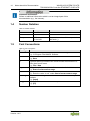 14
14
-
 15
15
-
 16
16
-
 17
17
-
 18
18
-
 19
19
-
 20
20
-
 21
21
-
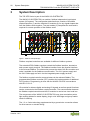 22
22
-
 23
23
-
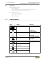 24
24
-
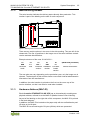 25
25
-
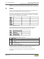 26
26
-
 27
27
-
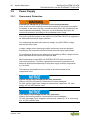 28
28
-
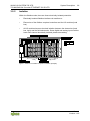 29
29
-
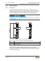 30
30
-
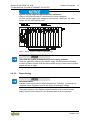 31
31
-
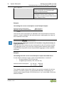 32
32
-
 33
33
-
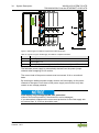 34
34
-
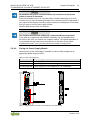 35
35
-
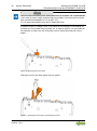 36
36
-
 37
37
-
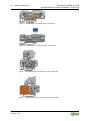 38
38
-
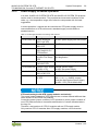 39
39
-
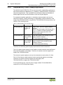 40
40
-
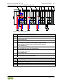 41
41
-
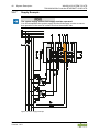 42
42
-
 43
43
-
 44
44
-
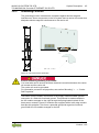 45
45
-
 46
46
-
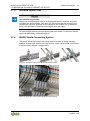 47
47
-
 48
48
-
 49
49
-
 50
50
-
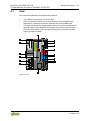 51
51
-
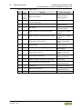 52
52
-
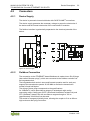 53
53
-
 54
54
-
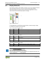 55
55
-
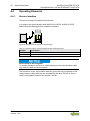 56
56
-
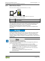 57
57
-
 58
58
-
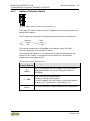 59
59
-
 60
60
-
 61
61
-
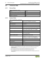 62
62
-
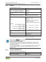 63
63
-
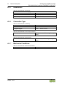 64
64
-
 65
65
-
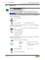 66
66
-
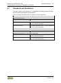 67
67
-
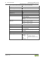 68
68
-
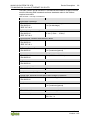 69
69
-
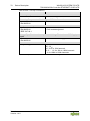 70
70
-
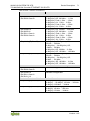 71
71
-
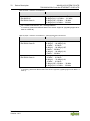 72
72
-
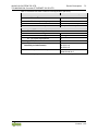 73
73
-
 74
74
-
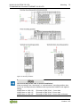 75
75
-
 76
76
-
 77
77
-
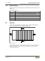 78
78
-
 79
79
-
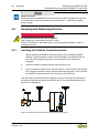 80
80
-
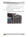 81
81
-
 82
82
-
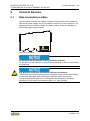 83
83
-
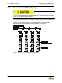 84
84
-
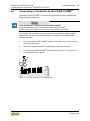 85
85
-
 86
86
-
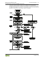 87
87
-
 88
88
-
 89
89
-
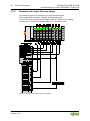 90
90
-
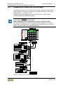 91
91
-
 92
92
-
 93
93
-
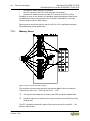 94
94
-
 95
95
-
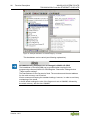 96
96
-
 97
97
-
 98
98
-
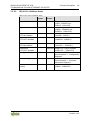 99
99
-
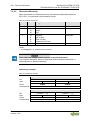 100
100
-
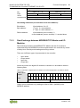 101
101
-
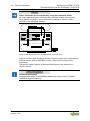 102
102
-
 103
103
-
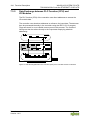 104
104
-
 105
105
-
 106
106
-
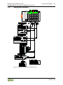 107
107
-
 108
108
-
 109
109
-
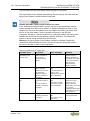 110
110
-
 111
111
-
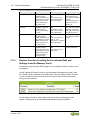 112
112
-
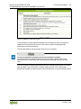 113
113
-
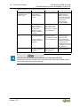 114
114
-
 115
115
-
 116
116
-
 117
117
-
 118
118
-
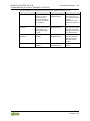 119
119
-
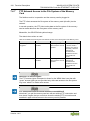 120
120
-
 121
121
-
 122
122
-
 123
123
-
 124
124
-
 125
125
-
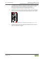 126
126
-
 127
127
-
 128
128
-
 129
129
-
 130
130
-
 131
131
-
 132
132
-
 133
133
-
 134
134
-
 135
135
-
 136
136
-
 137
137
-
 138
138
-
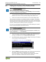 139
139
-
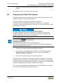 140
140
-
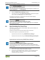 141
141
-
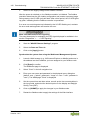 142
142
-
 143
143
-
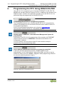 144
144
-
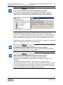 145
145
-
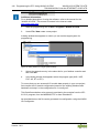 146
146
-
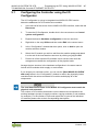 147
147
-
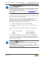 148
148
-
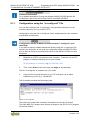 149
149
-
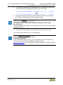 150
150
-
 151
151
-
 152
152
-
 153
153
-
 154
154
-
 155
155
-
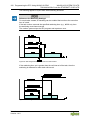 156
156
-
 157
157
-
 158
158
-
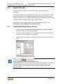 159
159
-
 160
160
-
 161
161
-
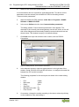 162
162
-
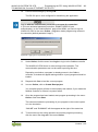 163
163
-
 164
164
-
 165
165
-
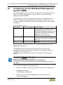 166
166
-
 167
167
-
 168
168
-
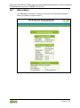 169
169
-
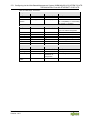 170
170
-
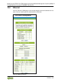 171
171
-
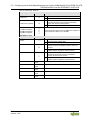 172
172
-
 173
173
-
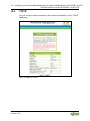 174
174
-
 175
175
-
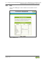 176
176
-
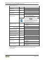 177
177
-
 178
178
-
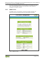 179
179
-
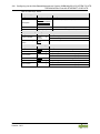 180
180
-
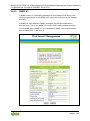 181
181
-
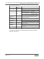 182
182
-
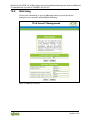 183
183
-
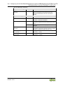 184
184
-
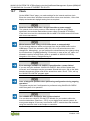 185
185
-
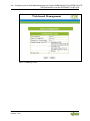 186
186
-
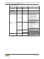 187
187
-
 188
188
-
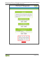 189
189
-
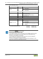 190
190
-
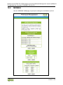 191
191
-
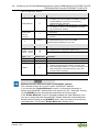 192
192
-
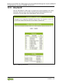 193
193
-
 194
194
-
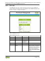 195
195
-
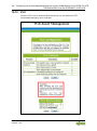 196
196
-
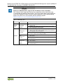 197
197
-
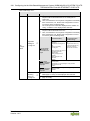 198
198
-
 199
199
-
 200
200
-
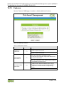 201
201
-
 202
202
-
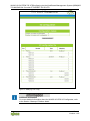 203
203
-
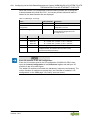 204
204
-
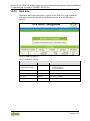 205
205
-
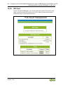 206
206
-
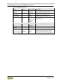 207
207
-
 208
208
-
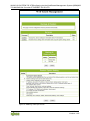 209
209
-
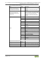 210
210
-
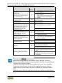 211
211
-
 212
212
-
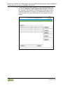 213
213
-
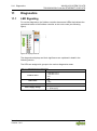 214
214
-
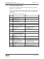 215
215
-
 216
216
-
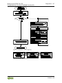 217
217
-
 218
218
-
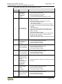 219
219
-
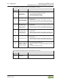 220
220
-
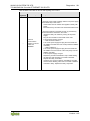 221
221
-
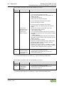 222
222
-
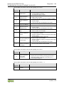 223
223
-
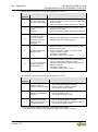 224
224
-
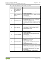 225
225
-
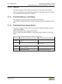 226
226
-
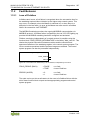 227
227
-
 228
228
-
 229
229
-
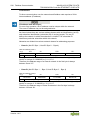 230
230
-
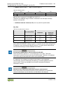 231
231
-
 232
232
-
 233
233
-
 234
234
-
 235
235
-
 236
236
-
 237
237
-
 238
238
-
 239
239
-
 240
240
-
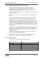 241
241
-
 242
242
-
 243
243
-
 244
244
-
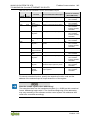 245
245
-
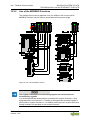 246
246
-
 247
247
-
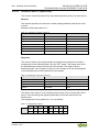 248
248
-
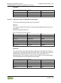 249
249
-
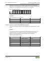 250
250
-
 251
251
-
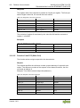 252
252
-
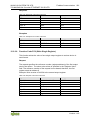 253
253
-
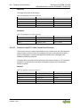 254
254
-
 255
255
-
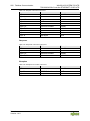 256
256
-
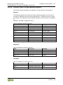 257
257
-
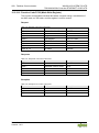 258
258
-
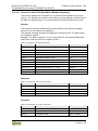 259
259
-
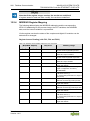 260
260
-
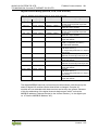 261
261
-
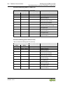 262
262
-
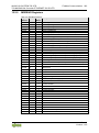 263
263
-
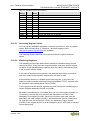 264
264
-
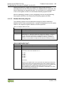 265
265
-
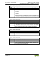 266
266
-
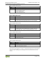 267
267
-
 268
268
-
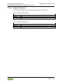 269
269
-
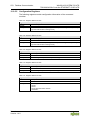 270
270
-
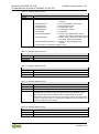 271
271
-
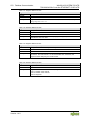 272
272
-
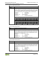 273
273
-
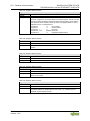 274
274
-
 275
275
-
 276
276
-
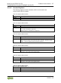 277
277
-
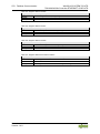 278
278
-
 279
279
-
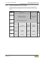 280
280
-
 281
281
-
 282
282
-
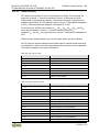 283
283
-
 284
284
-
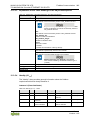 285
285
-
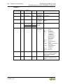 286
286
-
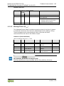 287
287
-
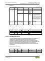 288
288
-
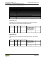 289
289
-
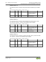 290
290
-
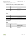 291
291
-
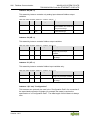 292
292
-
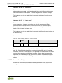 293
293
-
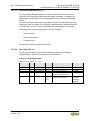 294
294
-
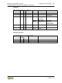 295
295
-
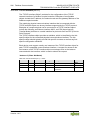 296
296
-
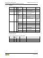 297
297
-
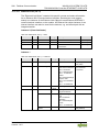 298
298
-
 299
299
-
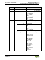 300
300
-
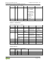 301
301
-
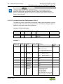 302
302
-
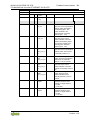 303
303
-
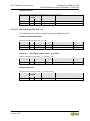 304
304
-
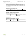 305
305
-
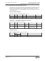 306
306
-
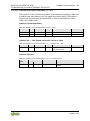 307
307
-
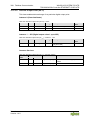 308
308
-
 309
309
-
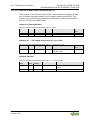 310
310
-
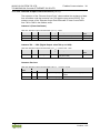 311
311
-
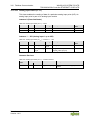 312
312
-
 313
313
-
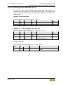 314
314
-
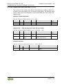 315
315
-
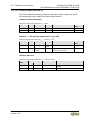 316
316
-
 317
317
-
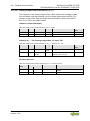 318
318
-
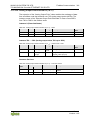 319
319
-
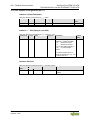 320
320
-
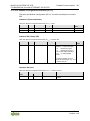 321
321
-
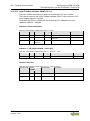 322
322
-
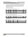 323
323
-
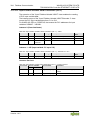 324
324
-
 325
325
-
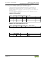 326
326
-
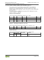 327
327
-
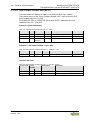 328
328
-
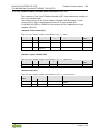 329
329
-
 330
330
-
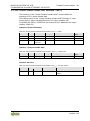 331
331
-
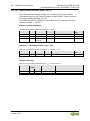 332
332
-
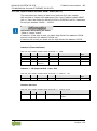 333
333
-
 334
334
-
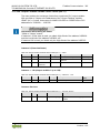 335
335
-
 336
336
-
 337
337
-
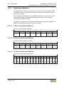 338
338
-
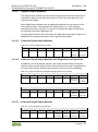 339
339
-
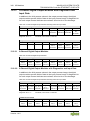 340
340
-
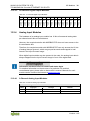 341
341
-
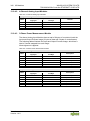 342
342
-
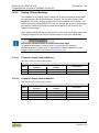 343
343
-
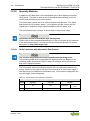 344
344
-
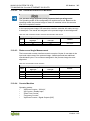 345
345
-
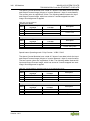 346
346
-
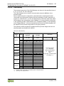 347
347
-
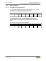 348
348
-
 349
349
-
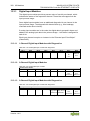 350
350
-
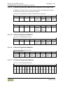 351
351
-
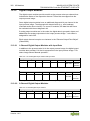 352
352
-
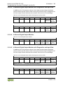 353
353
-
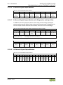 354
354
-
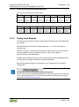 355
355
-
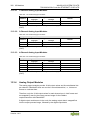 356
356
-
 357
357
-
 358
358
-
 359
359
-
 360
360
-
 361
361
-
 362
362
-
 363
363
-
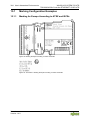 364
364
-
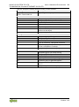 365
365
-
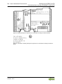 366
366
-
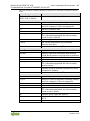 367
367
-
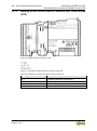 368
368
-
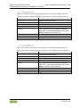 369
369
-
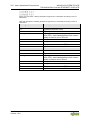 370
370
-
 371
371
-
 372
372
-
 373
373
-
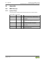 374
374
-
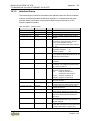 375
375
-
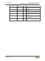 376
376
-
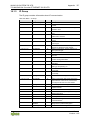 377
377
-
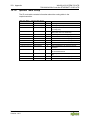 378
378
-
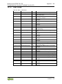 379
379
-
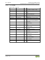 380
380
-
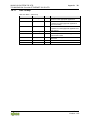 381
381
-
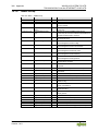 382
382
-
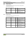 383
383
-
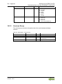 384
384
-
 385
385
-
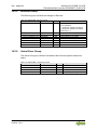 386
386
-
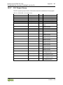 387
387
-
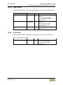 388
388
-
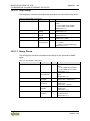 389
389
-
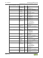 390
390
-
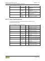 391
391
-
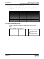 392
392
-
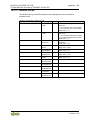 393
393
-
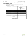 394
394
-
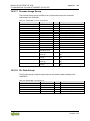 395
395
-
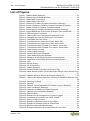 396
396
-
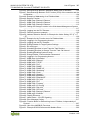 397
397
-
 398
398
-
 399
399
-
 400
400
-
 401
401
-
 402
402
-
 403
403
-
 404
404
-
 405
405
-
 406
406
-
 407
407
-
 408
408
-
 409
409
-
 410
410


WAGO ETHERNET Controller /XTR Manuale utente
- Tipo
- Manuale utente
- Questo manuale è adatto anche per
in altre lingue
Documenti correlati
Altri documenti
-
 West Control Solutions Rail line MODTCP Manuale utente
-
Christie LX1750 Manuale utente
-
Krone BA EasyCut R 400 Istruzioni per l'uso
-
SICK Flexi Gateway GPNT1 Expansion module - gateway Istruzioni per l'uso
-
CAME 803XC-0020 Guida d'installazione
-
ABB RED650 Applications Manual
-
Advantech ADAM-5000/TCP Series Manuale utente
-
Hitachi PLC Getting Started
-
 Orolia PRISMA Compliance Manuale utente
-
IFM CR7032 Istruzioni per l'uso

