Coemar ParLite Led T Instructions Manual
- Categoria
- Stroboscopi
- Tipo
- Instructions Manual


par Lite LED White
numero di serie/serial number
data di acquisto/date of purchase
fornitore/retailer
indirizzo/address
cap/città/suburb
provincia/capital city
stato/state
tel./fax/
Prendete nota, nello spazio apposito, dei dati relativi al modello e al rivenditore del vostro Par Lite Led White:
ci permetteranno di assistervi con la massima rapidità e precisione.
Please note in the space provided above the relative service information of the model and the retailer from
whom you purchased your
Par Lite Led White
: this information will assist us in providing spare parts, repairs
or in answering any technical enquiries with the utmost speed and accuracy.
ATTENZIONE
:
la sicurezza dell’apparecchio è garantita solo con l’uso appropriato delle presenti istruzioni, per-
tanto è necessario conservarle.
WARNING
: t
he security of the fixture is granted only if these instructions are strictly followed; therefore it is
absolutely necessary to keep this manual.
Users Manual Version 1.0
edition October 2006

Index
1. Packaging and transportation Pag. 4
1.1. Packaging “ 4
1.2. Transportation “ 4
2. General information Pag. 4
2.1. Important safety information “ 4
2.2. Warranty conditions “ 4
2.3. CE Certification “ 4
3. Product specifications Pag. 5
3.1. Technical characteristics “ 5
3.2. Dimensions “ 5
3.3. Projector components “ 5
4. Installation Pag. 6
4.1. Mechanical installation “ 6
4.2. Attaching a safety chain “ 7
4.3. Adjusting beam direction “ 7
4.4. Opening and closing up the projector “
8
4.5. Adjusting the beam angle “ 8
5. Powering up Pag. 10
5.1. Operating voltage and frequency “ 10
5.2. Mains connection “ 10
6. DMX signal functions Pag. 11
6.1. Connecting DMX signal “ 11
6.2. Turning on the projector “ 11
6.3. DMX addressing “ 12
6.4. DMX functions “ 12
7. Test function Pag. 13
8. Light ON function Pag. 13
9. Auto function Pag. 14
9.1. Master/Slave mode “ 14
9.2. Stand Alone mode “ 15
10. Switch panel signals Pag. 16
11. Thermal protection Pag. 16
12. Maintenance Pag. 16
12.1. Replacing blown fuses “ 16
12.2. Periodic maintenance “ 17
13. Spare parts Pag. 17
14. Accessory Pag. 17
15. Frequently asked questions Pag. 17
English
3

Congratulations on having purchased a Coemar product. You have assured yourself of a fixture of the highest quality, both in compo-
nentry and in the technology used. We renew our invitation to you to complete the service information on the previous page, to expe-
dite any request for service information or spares (in case of problems encountered either during, or subsequent to, installati on). This
information will assist in providing prompt and accurate advice from your Coemar service centre..
Following the instructions and procedures outlined in this manual will ensure the maximum efficiency of this product for years to come.
1.1. Packaging
Open the packaging and ensure that no part of the equipment has suffered damage in transit. In case of damage to the equipment,
contact your carrier immediately by telephone or fax, following this with formal notification in writing.
Packing list
Ensure the packaging contains:
1 Par Lite Led White
1 Instruction manual
1.2. Transportation
The Par Lite Led White White should be transported in either its original packaging or in an appropriate flight case.
2.1. Important safety information
Fire prevention:
1. Never locate the fixture on a flammable surface.
2. Minimum distance from flammable materials: 0.5 m.
3. Minimum distance from the closest illuminable surface: 0,5 m.
4. Replace any blown or damaged fuses only with those of identical values. Refer to the schematic diagram if there is any doubt.
5. Connect the projector to mains power via a thermal magnetic circuit breaker.
Prevention against electric shock:
1. High voltage is present in the internal of the unit. Isolate the projector from mains supply prior to performing any function which
involves touching the internal of the unit.
2. For mains connection, adhere strictly to the guidelines outlined in this manual.
3. The level of technology inherent in the Par Lite Led White requires the use of specialised personnel for all service applications; refer
all work to your authorised Coemar service centre.
4. A good earth connection is essential for proper functioning of the projector. Never operate the unit without proper earth connection.
5. The mains cable should not come into contact with other cabling.
6. Never handle the unit with wet hands or in a
damp environment.
Safety:
1. The projector should always be installed with bolts, clamps, and other fixings which are suitably rated to support the weight o f the unit.
2. Always use a secondary safety chain of a suitable rating to sustain the weight of the unit in case of the failure of the primar y fixing point..
3. Never install the fixture in an enclosed area lacking sufficient air flow; the ambient temperature should not exceed 35°C.
4. The external surface of the unit, at various points, may exceed 80°C. Never handle the unit until at least 10 minutes have elapsed
since the unit was turned off..
Protection rating of the body against liquids and solids:
1. The standard version of the fixture is classified ordinary apparatus; its protection grade against penetration by external agents,solid or
liquid, is IP 20
2. The IP version of the projector has an IP 66 protection rating; this indicates that it is protected against dust and significant showers
of water. This protection rating allows the fixture to be installed in an exposed location in inclement weather.
2.2. Warranty conditions
1. The fixture is guaranteed for a period of 36 months against manufacturing faults and faulty materials.
2. Faults due to incorrect operation or operation in an inappropriate manner are not covered by the warranty.
3. The warranty is immediately void if the fixture has been operated or serviced by unqualified or unauthorised personnel.
4. The warranty does not include fixture replacement.
5. The model and serial numbers must be supplied for any warranty claims or advice from our authorised service personnel.
2.3. CE Certification
1. The fixture satisfies the essential requirements of the directive EMC 89/336/EEC, 93/68/EEC, BT73/23/EEC.
2. The fixture is conform to UL STD 1573 and certified CSA STD C22.2/166.
2. The fixture is in accordance with the standard EN 50419 (RoHS) and satisfies the requirements of the directive 2002/96/EC (WEEE).
3041025
2. General information
1. Packaging and transportation
English
4

3.1. Technical characteristics
Power: 90/240 Vac 50/60Hz Autosensing
Nominal current: 0.2A @ 230Vac
0.5A @ 115V
Power factor: cos ϕ = 0.8
Led power: 36 Led x 1W
Minimum ambient temperature: -15°C / 5°F
Maximum ambient temperature: 35°C / 95°F
Weight: 3.6 Kg / 7.9 lbs
IP Rating: IP20 (standard version)
IP66 (IP version)
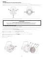
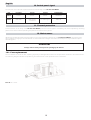
3.2. Dimensions
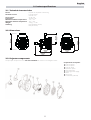
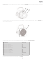
3.3. Projector components
The principal components of the Par Lite Led White are shown in the diagram below.
Components description
1. IP20 rear panel
2. IP66 rear panel
3. Projector body
4. Dip-switch panel
5. Led control PCB
6. Switching power supply
7. Head
8. Lens group
9. Front frame (optional)
212mm
8.35”
184mm
7.24”
268mm
10.55”
211mm
8.30”
268mm
10.5”
167mm
6.46”
3. Product specifications
5
English

6
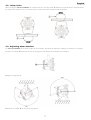
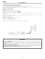
4.1. Mechanical installation
Par Lite Led White may be floor mounted or hung from an appropriate structure in any position.
Permanent installation
Use the three holes “A” (Ø13) on the yoke of the Par Lite Led White for robust, permanent installation.
Mobile installations
If hanging the fixture from a lighting truss or similar, we recommend the use of appropriate clamps “B”, affixed to the yoke in the holes
“A” provided, as shown in the following diagram.
Never install the fixture in a position in an accessible position to personnel who may ignore or be unaware of the safety directions men-
tioned in this manual.
ATTENTION!!
Always ensure that your support structure and fixings (bolts, clamps, etc.)
are rated to support the weight of the fixture.
A
30mm
1.18”
30mm
1.18”
4. Installation
English

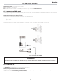
4.2. Safety chain
When hanging the Par Lite Led White we recommend the use of a safety chain “C” affixed to the yoke and to the suspension device.
The safety chain should be either a metal wire rope or a metal chain, both suitably rated for the purpose.
4.3. Adjusting beam direction
The Par Lite Led White can be tilted to adjust the beam output. To perform this adjustment, follow the instructions set out below.
1. Loosen the handle “D” located on the side of the projector, thus allowing the inclination to be changed.
2. Adjust the projector’s tilt.
3. Refasten the handle “D” on the side of the projector.
7
English

4.4. Opening and closing up the projector
The various procedures which follow can only be performed with the projector housing removed.
To gain access to the internal of the projector use a suitable screwdriver to remove the 3 screws “E” which affix the front frame and
remove it.
In the IP version, to access the rear area (switch panel), fully untighten the 4 screws "F" that fix of the rear panel and remove it from the unit.
You should now have complete access to the internal of the projector and can proceed to carry out the procedures described below.
Close the unit by following the previous points the other way round.
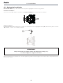
4.5. Adjusting the beam angle
Several optional optical groups are available for Par Lite Led White. They are used to vary the beam dimension and make it suitable
for different lighting applications and specifically: a group of lenses for a larger projection angle, a flood reflector and se veral filters
that
can be fitted either internally or externally to the unit
The standard optical group, fitted on Par Lite Led White, is composed by a group of lenses that gives 12° beam angle.
Here following you will find instructions to install different optical groups.
1. Open the unit as shown on paragraph 4.4 Open and close the unit
2. Remove the 3 screws “G”.
3. Replace the lenses “L” and ensure that the led of “H” disc fit perfectly in the lenses seats
If you wish to use an optional filter holder (code CO9169) follow the instructions as per point 4 and 5.
4. After having positioned the lenses group insert the “M” filter
5. Lock it with the “P” filter holder
6. Tighten the 3 “G” fixing screws
7. Close the unit
ATTENTION!!
Remove mains power prior to opening up the projector.
In the IP version, before close up the unit, check that the garnishings are inserted in their places.
Both screws “E” and “F” must be uniformly fixed, screwing them alternately in short steps.
8
English

To further increase the beam angle the “R” flood reflector is available (code CO9168) and it must be fitted instead of the lenses group
and filter holder.
To vary the wideness of the beam without opening the unit, it’s possible to install an external filter holder “S” (code CO9169/1), as
shown on following drawing.
The following table details the range of beam angle and diffusion filters available for the Par Lite Led White.
To shape the beam you can use an external barndoor (code CO9164).
Optical group Beam angle
Narrow Lenses (standard) 12°
Narrow Lenses + Light Frost Filter 17°
Narrow Lenses + Frost Filter 25°
Narrow Lenses + Strip Frost Filter Beam Shake
Medium Lenses (cod. CO9167) 30°
Medium Lenses + Light Frost Filter 35°
Medium Lenses + Frost Filter 45°
Medium Lenses + Strip Frost Filter Beam Shake
Flood 130°
9
English

5.1. Operating voltage and frequency
The fixture may operate at voltages ranging from 90 to 250V AC at a frequency of 50 or 60 Hz.
It is not necessary to effect any setup procedures, Par Lite Led White will automatically adjust its operation to suit any
frequency or voltage within this range.
5.2. Mains connection
Cabling
The mains cable provided can be one of the following type:
1. Neoprene cable Type HO7RN-F 3x1.5 mmq (cod. CV5333)
2. Neoprene cable type FT-2 P-7K 3x1.5 mmq (cod. CV5307)
Both types are suitable for outdoor applications and comply to the most recent international standards: CEI 20-19, UNEL 35364,
CENELEC HD 22.
N.B. In case of cable replacement, similar cable with comparable qualities must be used exclusively (cable 3x1.5 ø external 10 mm, rated
450/750V, operating temperature -25° +60°.
Connection to mains power
for connection purposes, ensure you plug is of a suitable rating:
•230/240V 0.2 amps constant current.
•208V 0.25 amps constant current.
•100/115V 0.5 amps constant current.
Locate the mains cable which exits the base of the unit and connect as shown below:
ATTENTION!!
• The use of a thermal/magnetic circuit breaker for each fixture is recommended. Strict adherence to regulatory norms
is strongly recommended.
• Par Lite Led White should not be powered through a Dimmer as this may damage the internal switching power-
supply.
• Prior to connecting the device to mains power, ensure that the mains characteristics are within the recommended
range for use with the Par Lite Led White.
• A good earth connection is essential for the correcdt operation of the Par Lite Led White. Never install the unit unless
the yellow/gree earth cable is securely connected.
• All cabling and connections should be carried out by suitably qualified personnel.
5. Powering up
10
English

Par Lite Led White can operate in three modes:
1. using DMX512 control signal
2. automated “STAND ALONE” or “MASTER/SLAVE” modes (see chapter 9. AUTO function)
6.1. Connecting DMX signal
Control signal is digital and is transmitted via two pair screened cable, as recommended in international standards for the transmission
of DMX512. Connection is serial, utilising the XLR3 sockets located on the rear panel of the Par Lite Led White.
Signal connection via the XLR3connectors
Connection is to international standards. Connection is as indicated below:
pin 1 = GND
pin 2 = data -
pin 3 = data +
Should your DMX 512 controller output signal via a cannon XLR5 (5 pin), pins 4 and 5 should remain unconnect
ed.
6.2. Powering up
After having followed the preceding steps, turn on mains power on to the unit.
The POWER led located near the dip-switch panel will come on.
Turning on power with DMX signal connected.
The yellow DMX led will flash to indicate that DMX 512 is being correctly received. If the yellow led is off, DMX
signal is not being
received (see section 15. Frequently asked questions).
ATTENTION!!
Ensure that all data conductors are isolated from one another, the screening and the metal housing of the connector.
Pin number 1 and the housing should never be connected to mains power.
6. DMX signal functions
11
English

6.3. DMX addressing
Via the dip-switch panel, it is possible to assign a DMX address to the fixture. The address is determined by the sum of the values associated
with the dip switches set to the on position.
Each Par Lite Led White utilises 1 or 3 channels of DMX 512 signal for complete control.
IMPORTANT NOTE: the following points are valid for all the instructions which follow.
1. Setting a dip-switch to the ON position activates its function
2. The DMX address may be altered without the need to turn the Par Lite Led White off.
The following are examples only for setting DMX addresses.
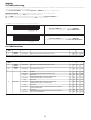
6.4. DMX functions
Par Lite Led White number 2 Address DMX 007
is obtained by setting dip-switches 1, 2 & 4 to the ON position
ON
256
auto
test
light on
DR1
1 2 4 8 16 32 64 128
IR
Par Lite Led White number 1 Address DMX 001
is obtained by setting dip-switch 1 to the ON position
256
auto
test
light on
DR1
ON
1 2 4 8 16 32 64 128
IR
12
English
3Ch
3Ch
channel
DMX
function type of control effect
1
master
dimmer
proportional -%0552-0%001 ot 0 morf ytisnetni tuptuo suonimul tsujda 100%
2
dimmer
fine
proportional fine dimmer control 16 bit 0 - 255 0% - 100%
step no %4-%09-0tceffe
proportional %22-%475-01tsaf ot wols morf ,tceffe gniborts deeps elbairav
%32-%3295-85eborts potspets
proportional
sequenced pulse effect, slow closing, fast opening
(variable speed pulsing, from slow to fast)
60 - 108 24% - 42%
%34-%34011-901eborts potspets
proportional
sequenced pulse effect, fast closing, slow opening
(variable speed pulsing, from slow to fast)
111 - 159 44% - 62%
%36-%36161-061eborts potspets
proportional
random strobe effect with variable speed from slow to fast and
synchronised channels
162 - 207 64% - 81%
%28-%28902-802eborts potspets
proportional
random strobe effect with variable speed from slow to fast and
non-synchronised channels
210 - 255 82% - 100%
decimal percentage
3 strobe effect
channel
DMX
function type of control effect
1
master
dimmer
proportional -%0552-0%001 ot 0 morf ytisnetni tuptuo suonimul tsujda 100%
decimal percentage
3. To set the 3 channels mode set the dip-switch 3Ch to the on position.

With the dip-switch set to the ON position, Par Lite Led White will test each individual channel without the need for a DMX controller
to be connected.
For example:
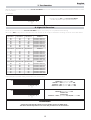
Via this function the leds of the Par Lite Led White may be set to always on at a predetermined intensity.
When set to ON the dip-switch, illumination level and channel can be set by a combination of settings as shown in the table below.
Other examples of possible setting combinations are shown below.
ATTENTION!!
Setting the Light ON dip-switch to active inhibits control via DMX signal.
The three channel dip-switches set to the OFF position turn off the channel.
LIGHT ON dip-switch set to ON
channel 1 off
channel 2 off
channel 3 at 100% (dip-switches 64, 128, 256 set to ON)
ON
256
auto
test
light on
DR1
1 2 4 8 16 32 64 128
IR
LIGHT ON dip-switch set to ON
channel 1 at 20% (dip-switch 1 set to ON)
channel 2 at 30% (dip-switch 16 set to ON)
channel 3 at 50% (dip-switch 256 set to ON)
ON
256
auto
test
light on
DR1
1 2 4 8 16 32 64 128
IR
dip-switch 1 dip-switch 2 dip-switch 4 channel 1
on off off illumination level 20%
off on off illumination level 30%
on on off illumination level 40%
off off on illumination level 50%
on off on illumination level 60%
off on on illumination level 80%
on on on illumination level 100%
dip-switch 8 dip-switch 16 dip-switch 32 channel 2
on off off illumination level 20%
off on off illumination level 30%
on on off illumination level 40%
off off on illumination level 50%
on off on illumination level 60%
off on on illumination level 80%
on on on illumination level 100%
on off off illumination level 20%
off on off illumination level 30%
on on off illumination level 40%
off off on illumination level 50%
on off on illumination level 60%
off on on illumination level 80%
on on on illumination level 100%
dip-switch 256 channel 3dip-switch 64 dip-switch 128
8. Light ON Function
set the dip-switch to ON on the Par Lite Led White.
The fixture will perform a quick sequential channel test
ON
256
auto
test
light on
DR1
1 2 4 8 16 3 2 64 128
IR
7. Test function
13
English
3Ch
3Ch
3Ch

This function can be used to determine the operating mode of the projector (either STAND ALONEor MASTER/SLAVE ), make
program selections or alter the crossfade times. Setting this function to on inhibits control via DMX signal.
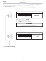
9.1. MASTER/SLAVE mode
In MASTER/SLAVE mode, it is possible to control, via a projector set as MASTER, a series of Par Lite Led White units set to act as SLAVE
fixtures. The table below displays the settings required for fixtures to be connected in this manner.
To configure a Par Lite Led White as MASTERis simply a matter of setting the Auto dip-
switch to the ON position and selecting a program for it to follow by making a selection
from the following dip-switches: 1-2-4-8-256.
There are 4 programs which can be selected.
- dip switches 1-2-4-8 select programs 1, 2, 3, and 4 respectively.
- dip-switch 256 runs all four programs sequentially
To configure a Par Lite Led White as SLAVE is simply a matter of setting the Auto dip-
switch to the ON. All other dip-switches should be set to OFF.
Par Lite Led White
set to SLAVE
ON
256
auto
test
light on
DR1
1 2 4 8 16 32 64 128
IR
SLAVE
ATTENTION!!
It is only possible to select one program at a time.
Par Lite Led White set as MASTER
running program 1
ON
256
auto
test
light on
DR1
1 2 4 8 16 32 64 128
IR
MASTER
9. Auto function
14
English
3Ch3Ch

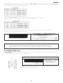
After having selected the program you wish to run, dip-switches 16 and 32 may be used to set the wait time for each scene in the
selected program. In this manner, programs can be made to run faster or slower according to your requirements. The following table
outlines the dip-switch settings and their associated wait times.
Via dip-switches 64 and 128 it is possible to set the fade times for each scene in the selected program.
The following table outlines the dip-switch settings and their associated fade times.
The timing for each scene in a program is therefore a sum of the crossfade and hold times as set via these dip-switches.
The following table gives an example of a possible setting.
9.2. STAND ALONE mode
In STAND ALONEmode the projector operates independently with no need for DMX signal. It is possible to select the program which
the projector runs and to alter the hold and crossfade times.
To configure the Par Lite Led White as STAND ALONEsimply set dip-switch Auto to the
ON position and select the program you wish to run and the hold and crossfade times to
follow
, as described in the previous section.
Par Lite Led White set as STAND
ALONE running program 1
ON
256
auto
test
light on
DR1
1 2 4 8 16 32 64 128
IR
STAND ALONE
ATTENTION!!
When the AUTO function is selected DMX signal reception is disabled to avoid system conflicts.
Par Lite Led White set as a MASTER running program 3
hold time 30 sec. crossfade time 10 sec.
Set the AUTO and 4 dipswitches to ON will select the fixture as MASTER
running program 3.
Setting dip-switch 16 to OFF and 32 to ON will set a hold time of 30 sec.
Dip-switch 64 to ON and 128 to OFF will set a crossfade time of 10 sec.
ON
256
auto
test
led on
DR1
1 2 4 8 16 32 64 128
IR
dip-switch 64 dip-switch 128
off off crossfade time 3 second
on off crossfade time 10 second
off on crossfade time 30 second
on on crossfade time 1 minute
speed (fade time)
dip-switch 16 dip-switch 32
off off hold time 3 second
on off hold time 10 second
off on hold time 30 second
on on hold time 1 minute
time (wait time)
15
English
3Ch
3Ch

The two leds on the dip-switch panel indicate the functionality of the Par Lite Led White.
A thermal sensor in the body of the Par Lite Led White protects the fixture against overheating. The sensor operates by removing
power to the leds should the operating temperature exceed the factory preset.
Whilst every possible precaution has been taken to ensure the trouble-free operation of your Par Lite Led White, the following peri-
odic maintenance is highly recommended. We recommend that the voltage to the unit be removed prior to any maintenance proce-
dure taking place.
14.1. Fuse replacement
Use a multimeter to check the fuse, replacing any faulty or damaged fuses with ones of equal value, dimensions and characterist ics.
The following diagram indicates the positioning and characteristics of the protection fuses in the fixture.
Fuse A: 4A T 250V
ATTENTION!!
Always remove mains power prior to opening up the fixture!
12. Maintenance
11. Thermal protection
Led Function Led on Led off Led flashing
Green
Power Present Absent Undefined
Yellow
DMX state
DMX poorly
connected
No DMX signal DMX OK
10. Switch panel signal
16
English

14.2. Periodic maintenance
Mechanicals
Check that the units is not mechanically damaged. Regularly clean the glass by using a soft cloth with a specific cleaning liqu id and, if
necessary, replace the damaged parts.
Electrical components
Check all electrical components for correct earthing, oxidation and proper attachment of all connectors, cleaning and refastening if necessary.
All the components of the Par Lite Led White are available as spare parts from your Coemar service centre.
Accurate description of the fixture, model number, and type will assist us in providing for your requirements in an efficient and effective
manner.
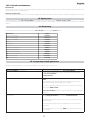
In the table below are listed all the accessory of the Par Lite LED and the related Coemar code.
The diagram below indicates some possible problems and solutions
if they should occur.
Problem Possible solution
Par Lite Led White won’t turn on. Mains power is not available to the Par Lite Led White:
• Check that the green Led is on, if so check the incoming voltage to
the Par Lite Led White.
• Check the fuse.
Par Lite Led White doesn’t respond to DMX signal Incoming DMX may not be being received by the Par Lite Led
White:
• check that the led indicating DMX input is flashing. If not, check the
DMX console’s output and any cabling for continuity .
• Check the dip-switch panel to ensure that no functions are selected
which inhibit DMX control.
• Par Lite Led White may be incorrectly addressed. Check the DMX
addressing.
The Par Lite Led White is set to auto but is not running
any programs
In addtion to setting the AUTO dip-switch to on,
it is necessary to also
select a program number (see section 9. AUTO function).
• Multiple programs have been selected - only one program at a time
may be selected.
• Check that amongst the interconnected fixtures, only one has bee
set to Master.
• Ensure that there is no incoming DMX signal (this may cause a con-
flict in signals).
15. Frequently asked questions
Descrizione Codice
1.
12° lens assembly CO9164
2. 12° lens assembly CO9167/1
3.
30° lens assembly CO9167
4. Flood CO9168
5. Inside gel CO9169
6.
Gel CO9169/1
7. Rear panel IP20 silver PAN07
8. Rear panel IP20 black PAN07/1
9. Rear panel IP66 silver PAN08
10. Rear panel IP66 black PAN08/1
11. XLR3 connector CO9189/1
12. XLR5 connector CO9189
14. Accessory
13. Spare parts
17
English

Coemar Lighting Srl
via Carpenedolo, 90 - 46043 Castiglione delle Stiviere (Mantova) Italy
ph. +39 03761514412 - fax +39 03761514380
info@coemar.com
Coemar si riserva il diritto di apportare modifiche senza preavviso.
Coemar reserves the right to effect modifications without notification
3041025
-
 1
1
-
 2
2
-
 3
3
-
 4
4
-
 5
5
-
 6
6
-
 7
7
-
 8
8
-
 9
9
-
 10
10
-
 11
11
-
 12
12
-
 13
13
-
 14
14
-
 15
15
-
 16
16
-
 17
17
-
 18
18


Coemar ParLite Led T Instructions Manual
- Categoria
- Stroboscopi
- Tipo
- Instructions Manual
in altre lingue
- English: Coemar ParLite Led T