DTS X-BRICK Manuale utente
- Categoria
- Proiettori
- Tipo
- Manuale utente
Questo manuale è adatto anche per

X-BRICK
USER’S MANUAL rel. 1.0 GB

2
Le informazioni contenute in questo documento sono state attentamente redatte e
controllate. Tuttavia non è assunta alcuna responsabilità per eventuali inesattezze.
Tutti i diritti sono riservati e questo documento non può essere copiato, fotocopiato,
riprodotto per intero o in parte senza previo consenso scritto della D.T.S .
D.T.S. si riserva il diritto di apportare senza preavviso cambiamenti e modifiche
estetiche , funzionali o di design a ciascun proprio prodotto. D.T.S non assume alcuna
responsabilità sull’uso o sull’applicazione dei prodotti o dei circuiti descritti.
The information contained in this publication has been carefully prepared and
checked. However, no responsibility will be taken for any errors. All rights are
reserved and this document cannot be copied, photocopied or reproduced, in part or
completely, without prior written consent from D.T.S.
D.T.S. reserves the right to make any aesthetic, functional or design modifications to
any of its products without prior notice. D.T.S. assumes no responsibility for the use or
application of the products or circuits described herein.
Les informations contenues dans le présent manuel ont été rédigées et contrôlées
avec le plus grand soin. Nous déclinons toutefois toute responsabilité en cas
d'éventuelles inexactitudes. Tous droits réservés. Ce document ne peut être copié,
photocopié ou reproduit, dans sa totalité ou partiellement, sans le consentement
préalable de D.T.S.
D.T.S. se réserve le droit d'apporter toutes modifications et améliorations esthétiques,
fonctionnelles ou de design, sans préavis, à chacun de ses produits. D.T.S. décline
toute responsabilité sur l'utilisation ou sur l'application des produits ou des circuits
décrits.
Las informaciones contenidas en este documento han sido cuidadosamente
redactadas y controladas. Con todo, no se asume ninguna responsabilidad por
eventuales inexactitudes. Todos los derechos han sido reservados y este documento
no puede ser copiado, fotocopiado o reproducido, total o parcialmente, sin previa
autorización escrita de D.T.S.
D.T.S. se reserva el derecho a aportar sin previo aviso cambios y modificaciones de
carácter estético, funcional o de diseño a cada producto suyo. D.T.S. no se asume
responsabilidad de ningún tipo sobre la utilización o sobre la aplicación de los
productos o de los circuitos descritos.

3
INDEX:
1- SYMBOLS ................................................................................................................. 4
2- GENERAL WARNING .............................................................................................. 5
3- GENERAL WARRANTY CONDITIONS .................................................................... 5
4- TECHNICAL FEATURES ......................................................................................... 5
5- ACCESSORIES ........................................................................................................ 7
6- IMPORTANT SAFETY INFORMATION .................................................................... 8
6.1 Fire prevention...................................................................................................... 8
6.2 Prevention of electric shock .................................................................................. 8
6.3 Safety ................................................................................................................... 8
6.4 Level of protection against the penetration of solid and liquid objects .................. 8
6.5 Waste Electrical and Electronic Equipment (WEEE) directive .............................. 9
7- INSTALLATION ........................................................................................................ 9
7.1 Floor mounting installation .................................................................................... 9
7.2 Ceiling mounting installation ............................................................................... 10
7.3 Display UV protection ......................................................................................... 11
7.4 Protection against liquids .................................................................................... 12
7.5 Movement ........................................................................................................... 12
7.6 Risk of fire .......................................................................................................... 12
7.7 Forced ventilation ............................................................................................... 13
7.8 Ambient temperature .......................................................................................... 13
8- INPUT / OUTPUT CONNECTIONS ......................................................................... 13
9- DMX SIGNAL CONNECTION ................................................................................. 14
9.1 DMX Addresses .................................................................................................. 15
9.2 Selecting the DMX address ................................................................................ 15
10- RDM FUNCTIONS ................................................................................................ 15
11- FIRMWARE UPDATING ....................................................................................... 21
12- DISPLAY FUNCTIONS ......................................................................................... 22
13- REC MODE ........................................................................................................... 29
14- ERROR MESSAGES ............................................................................................ 30
15- PERIODIC CLEANING ......................................................................................... 31
16- PERIODIC CONTROLS ........................................................................................ 31
17- HOLOGRAPHIC FILTER INSTALLATION ........................................................... 32
18- LENSES SET REPLACEMENT ............................................................................ 33
19- BARNDOOR INSTALLATION .............................................................................. 34
20- LED PIXEL INVERT FUNCTION REFERENCES ................................................. 35
21- DMX PROTOCOL ................................................................................................. 36

4
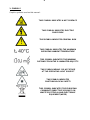
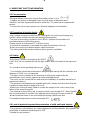
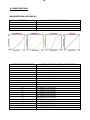
1- SYMBOLS
Graphic symbols used on this manual:
THIS SYMBOL INDICATES A HOT SURFACE
THIS SYMBOL INDICATES ELECTRIC
SHOCK RISK
THIS SYMBOL INDICATES GENERAL RISK
THIS SYMBOL INDICATES THE MAXIMUM
OPERATING AMBIENT TEMPERATURE
THIS SYMBOL INDICATES THE MINIMUM
DISTANCE FROM THE ILLUMINATED OBJECTS
THIS SYMBOL MEANS “DO NOT STARE
AT THE OPERATING LIGHT SOURCE”
THIS SYMBOL INDICATES
PHOTOBIOLOGICAL SAFETY
THIS SYMBOL INDICATES THE EUROPEAN
COMMUNITY DIRECTIVE 2012/19/EC ON
WASTE ELECTRICAL AND ELECTRONIC
EQUIPMENT (WEEE)
!

5
2- GENERAL WARNING
Read the instruction contained in this user manual carefully, as they give important
information regarding safety during installation, use and maintenance.
The unit is not for household use and must be installed by a qualified electrician or
experienced person.
Always disconnect the device from the mains before maintenance.
The device must always be equipped with an efficient ground connection.
3- GENERAL WARRANTY CONDITIONS
The unit is guaranteed for 36 months from the date of purchase against manufacturing
material defects.
The warranty covers defects in materials and workmanship. The warranty is not
appliable where a defect is caused by misuse or unauthorised repair of the product.
Any functional or/and physical modification of the product is not allowed.
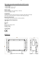
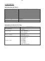
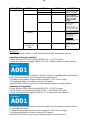
4- TECHNICAL FEATURES
DTS product codes:
03.LDB130S11FC X-BRICK FC Ultra-Narrow lenses Black finishing
Output
32 OSTAR STAGE “N” Full Color (RGBW) LEDs
15.300 lumens output
LED lifespan: 50.000 hours (70% lumen output)
Optical group
8° projection angle
Range of quick-mounting holographic filters included: 20° / 40° / 60°x10° (no mounting
tools required)
Uniform projection on surfaces
Color generation
16 million colors
Wide palette of pure uniform Whites with variable linear color temperature (2700K –
8000K)
16 gel filter emulations
Control
Wireless DMX transmitter/receiver (built-in)
DMX 512 / RDM protocols
LCD display + 4 capacitive touch keys
Internal operating system updatable via DTS Dongle Firmware Uploader
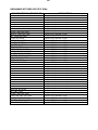
9 DMX modes:
DMX Full Operation modes
- Chase (default)
- Extended
- Sectors RGBW X4
- Sectors RGBW Fine X4
- Sectors RGBW + Shut + Dim X4

6
DMX Single Layer modes (compatibility with all BRICK models)
- Standard
- Global RGBW
- Global RGBW + Shut + Dim
- Global RGBW + Dim Fine
Power supply
Built-in full-range PSU 100-240Vac 50-60 Hz
Power consumption: 650W
Connections
PowerCON TRUE1 In/Out IP65 panel connectors with water-proof caps
XLR 5 pins In/Out IP65 panel connectors with water-proof caps
Internal safety devices
Overvoltage and overtemperature circuits protection
Operating ambient temperature
-20° / 40°
Physical
IP65
IK protection degree: IK09
Weight: 14 Kg
Finishing: Black
Certifications
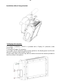
DIMENSIONS

7
5- ACCESSORIES
As standard
1 x Holographic filter 20° (code 0506A043.D18)
1 x Holographic filter 40° (code 0506A045.D18)
1 x Holographic filter 60°x10° (code 0506A092.D18)
1 x Cable with PowerCON TRUE1 female connector (code 02K0012267.0015)
1 x XLR 5-pole IP65 female cable connector (code 0508B177)
1 x XLR 5-pole IP65 male cable connector (code 0508B178)
1 x Display UV protection (code 03.LA.218)
1 x Omega bracket with “Fast Lock” (code 02K00467)
1 x User’s Manual
Optional (on request)
- Holographic filter 10° (code 0506A101.D18)
- Holographic filter 60° (code 0506A103.D18)
- Holographic filter 80° (code 0506A121.D18)
- Holographic filter 30x60° (code 0506A133.D18)
- Barndoor black finishing (code 03.LA.237.11)
- Visor black finishing (code 03.LA.236.11)
- Aliscaf clamp for tube diameter 50 mm (Max load 200 Kg) (code 0521A033)
(indicated for any kind of loads vertical / horizontal)
- Professional Quick trigger clamp (Max load 100 Kg) (code 0521A037) (not indicated
for horizontal load)
- “C” Clamp G60 (Max load 50 Kg) (code 0521A004) (not indicated for horizontal load)
- Safety cable 5 x 600 mm (Max load 60 Kg) (code 0521A038)
- DTS Dongle firmware uploader (code 03.LA.206)

8
6- IMPORTANT SAFETY INFORMATION
6.1 Fire prevention:
-Minimum distance from the closest illuminable surface: 0,5 m.
- Replace any blown or damaged fuses only with those of identical value.
Attention: the fuse replacement must be made by DTS personnel or experienced
person.
-Connect the unit to mains power via a thermal magnetic circuit breaker.
6.2 Prevention of electric shock:
-High voltage is present inside the unit. Unplug the unit prior to performing any
function which involves touching the inside of the projector.
-The level of technology inherent in the X-BRICK requires the assistance of
specialised personnel for all servicing.
Please refer to an authorised DTS service centre.
-A good earth connection is essential for proper functioning of the unit.
-Never connect the unit without proper earth connection.
-The fixture should be located in places with a good air ventilation.
6.3 Safety:
-Risk Group 2 product according to EN 62471.
CAUTION. Do not look directly into the light output. May be harmful to the eyes and
skin.
-Do not stare at the operating light source.
- The luminaire should be positioned so that prolonged staring into the luminaire at a
distance of 25,94 m is not expected.
-The light source contained in this luminaire shall only be replaced by the
manufacturer or his service agent or a similar qualified person.
-The unit is not for household use and must be installed by a qualified electrician or
experienced person.
-The projector should always be installed with bolts, clamps and other tools that are
capable of supporting the weight of the unit.
-Always use a second safety cable to sustain the weight of the unit in case of the
failure of the main fixing point.
-The external surface of the unit, at various points, may exceed 60°C. Never handle
the unit until at least 5 minutes have elapsed since the projector was turned off.
-Never install the fixture in an enclosed area lacking sufficient air flow.
The ambient temperature should not exceed 40°C.
6.4 Level of protection against the penetration of solid and liquid objects:
-The projector is classified as an outdoor appliance and its protection level against the
penetration of solid and liquid objects is IP65.
Suitable for wet locations.
!
!

9
6.5 Waste Electrical and Electronic equipment (WEEE) directive:
-The machine, accessories and packaging should be sorted for environmetal-friendly
Recycling.
For EC countries: according to the European Directive 2012/19/EC for Waste
Electrical and Electronic Equipment and its implementation into national right,
luminaires that are no longer usable must be collected separately and disposed of in
an environmentally correct manner.
7- INSTALLATION
The unit is suitable for wet locations.
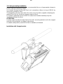
7.1 Floor mounting installation
BRICK may be either floor or ceiling mounted.
For floor mounting installation, X-BRICK is supplied with four rubber mounting feet on
its bracket to be used as a self standing projector.

10
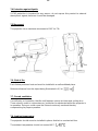
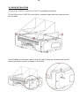
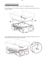
7.2 Ceiling mounting installation
For ceiling mounting installation, it is recommended the use of appropriate clamps to
fix the unit to the mounting surface.
An included Omega bracket with Fast Lock connections allows to hang X-BRICK by
using fixing clamps for truss.
The supporting structure from which the unit is hung should be capable of bearing the
weight of the unit, as should any clamps used to hung it.
For outdoor application where X-BRICK needs to be installed vertically keep the
unit display towards the floor.
ATTENTION:
A safety cable must be securely fixed to the unit’s mounting bracket and to the support
structure of the projector as shown in the picture.
A suitable safety cable (code 0521A038) is available on demand.
Installation with Omega bracket:

11
Installation without Omega bracket:
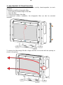
7.3 Display UV Protection
For outdoor installation, X-BRICK is provided with a Display UV protection (code
03.LA.218).
To install the Display UV protection:
Put in place the UV protection plate and the gasket on the display panel and fix both
with the 2 marked screws provided in the kit.
Fix the safety cable on the side cap with the marked screw and the washer provided in
the kit as shown in the picture.

12
7.4 Protection against liquids
If IP65 protection is impaired for any reason, do not expose this product to external
atmospheric agents, because it could be damaged.
7.5 Movement
The projector has a maximum movement of 105° for Tilt.
7.6- Risk of fire
Each fixture produces heat and must be installed in a well-ventilated place.
Minimum distance from the object being illuminated is 0,5 m.
7.7- Forced ventilation
You will note, on inspection, that the unit features various air inlets and cooling fans.
These should, under no circumstances, be blocked or obstructed whilst the projector is
in operation. Doing so could cause the fixture to seriously overheat thereby
compromising its proper operation.
7.8- Ambient temperature
The projector should never be installed in places that lack a constant air flow.
The ambient temperature should not exceed 40°C.

13
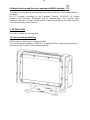
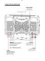
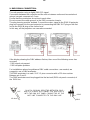
8- INPUT / OUTPUT CONNECTIONS
WIRELESS DMX
Built-in Lumen Radio
Wireless DMX
transmitter/receiver
Ergonomic double handles
MAINS IN
100-240Vac 50-60 Hz
PowerCON TRUE1 male
IP65 panel connector
with water-proof cap
MAINS OUT
100-240Vac 50-60 Hz (MAX 16A)
PowerCON TRUE1 female
IP65 panel connector
with water-proof cap
Max 4 X-BRICK units @ 230Vac
Max 2 X-BRICK units @ 100Vac
DMX OUT
XLR 5-pole female
IP65 panel connector
with water-proof cap
DMX IN
XLR 5-pole male
IP65 panel connector
with water-proof cap

14
9- DMX SIGNAL CONNECTION:
The unit operates using a digital DMX 512 signal.
Connection between the controller and the unit or between units must be carried out
using a two pair screened ø 0.5 mm.
Ensure that the conductors do not touch each other.
Do not connect the cable ground to the DMX connector chassis.
The plug housing must be isolated. Connect the mixer signal to the DMX IN projector
plug and connect it to the next projector by connecting the DMX OUT plug on the first
unit to the DMX IN plug of the second one.
In this way, all the projectors are cascade connected.
If the display showing the DMX address flashes, then one of the following errors has
occurred:
- DMX signal not present
- DMX reception problem
For Installations where long distance DMX cable connections are needed, we
suggest to use a DMX terminator.
The DMX terminator is a male XLR 3-5 pins connector with a 120 ohm resistor
Between pin 2 and 3.
The DMX terminator must be plugged into the last unit (DMX out panel connector) of
the DMX line.
PLACE A 120 OHM RESISTOR BETWEEN PIN 2
AND 3 OF A MALE XRL CONNECTOR AND PLUG IT
INTO THE DMX OUT PANEL CONNECTOR OF THE
LAST UNIT CONNECTED TO THE DMX LINE
1
2
3
5
4
OUT
120 ohm
PIN 3
PIN 2

15
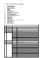
9.1 DMX addresses
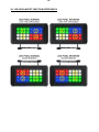
X-BRICK can be used in 9 DMX modes:
1. Standard (10 ch)
2. Chase (23 ch) (Default)
3. Extended (29 ch)
4. Global RGBW (4 ch)
5. Global RGBW + Shut + Dim (6 ch)
6. Global RGBW + Dim Fine (10 ch)
7. Sectors RGBW X4 (16 ch)
8. Sectors RGBW Fine X4 (32 ch)
9. Sectors RGBW + Shut + Dim X4 (24 ch)
DMX Full Operation modes
- Chase (default)
- Extended
- Sectors RGBW X4
- Sectors RGBW Fine X4
- Sectors RGBW + Shut + Dim X4
DMX Single Layer modes (compatibility with all BRICK models)
- Standard
- Global RGBW
- Global RGBW + Shut + Dim
- Global RGBW + Dim Fine
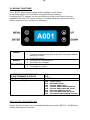
In order to use the unit in “Chase” mode (23 DMX channels) (Default), set the following
addresses on the mixer:
Projector 1 A001
Projector 2 A024 If you want to select the next projector, just add “23”
Projector 3 A047
….. A….
projector 6 A116
9.2 Selecting the DMX address
1) Press the UP-DOWN key until you reach the required DMX address. The numbers
on the display will start to flash (but the new DMX address hasn't yet been set).
2) Press ENTER to confirm your selection. The numbers on the display will stop
flashing and the projector is now controlled by the new DMX address.
TIPS: if you keep pushed the UP or DOWN keys, the channels are calculated more
quickly and you get a faster selection.

16
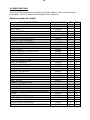
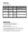
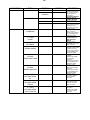
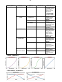
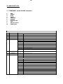
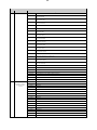
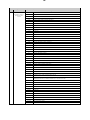
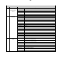
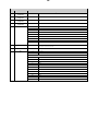
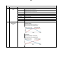
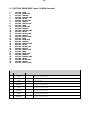
10- RDM FUNCTIONS
By using a RDM controller it is possible to set DMX address, DMX mode and other
parameters. X-BRICK accepts the following RDM commands:
RDM Device Model ID: 0x0D65
RDM PID DESCRIPTION
RDM PID VALUE
GET
SET
Category – Network Management
DISC_UNIQUE_BRANCH
0x0001
DISC_MUTE
0x0002
DISC_UN_MUTE
0x0003
Category – Status Collection
STATUS_MESSAGES
0x0030
X
STATUS_ID_DESCRIPTION
0x0031
X
Category - RDM Information
SUPPORTED_PARAMETERS
0x0050
X
PARAMETERS_DESCRIPTION
0x0051
X
Category – Product Information
DEVICE_INFO
0x0060
X
DEVICE_MODEL_DESCRIPTION
0x0080
X
MANUFACTURER_LABEL
0x0081
X
DEVICE_LABEL
0x0082
X
X
SOFTWARE_VERSION_LABEL
0x00C0
X
Category - DMX512 Setup
DMX_PERSONALITY
0x00E0
X
X
DMX_PERSONALITY_DESCRIPTION
0x00E1
X
DMX_START_ADDRESS
0x00F0
X
X
Category – Sensors
SENSOR_DEFINITION
0x0200
X
SENSOR_VALUE
0x0201
X
X
Category – Power/Lamp Settings
DEVICE_HOURS
0x0400
X
LAMP_HOURS
0x0401
X
Category – Display Settings
DISPLAY_INVERT
0x0500
X
X
Category – Control
IDENTIFY_DEVICE
0x1000
X
Category – Dimmer Settings (Additional Messages)
CURVE
0x0343
X
X
CURVE_DESCRIPTION
0x0344
X
OUTPUT_RESPONSE_TIME
0x0345
X
X
OUTPUT_RESPONSE_TIME_DESCRIPTION
0x0346
X
MODULATION_FREQUENCY
0x0347
X
X
MODULATION_FREQUENCY_DESCRIPTION
0x0348
X

17
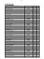
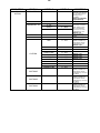
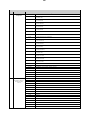
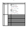
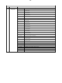
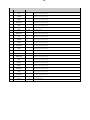
10- RDM FUNCTIONS
RDM PID DESCRIPTION
RDM PID VALUE
GET
SET
Category – Manufacturer-Specific PIDs
LED PIXEL INVERT
0x9039
X
X
FANS SETTING
0x903A
X
X
DISPLAY STANDBY
0x903C
X
X
BKGND-CHS CROSSFADE
0x903D
X
X
NO DMX ACTION
0x9002
X
X
RED NO DMX
0x9003
X
X
GREEN NO DMX
0x9004
X
X
BLUE NO DMX
0x9005
X
X
WHITE NO DMX
0x9006
X
X
INT NO DMX
0x900A
X
X
RED FINE NO DMX
0x9014
X
X
GREEN FINE NO DMX
0x9015
X
X
BLUE FINE NO DMX
0x9016
X
X
WHITE FINE NO DMX
0x9017
X
X
INT FINE NO DMX
0x9018
X
X
RED2 NO DMX
0x9019
X
X
GREEN2 NO DMX
0x901A
X
X
BLUE2 NO DMX
0x901B
X
X
WHITE2 NO DMX
0x901C
X
X
INT2 NO DMX
0x901D
X
X
RED2 FINE NO DMX
0x901E
X
X
GREEN2 FINE NO DMX
0x901F
X
X
BLUE2 FINE NO DMX
0x9020
X
X
WHITE2 FINE NO DMX
0x9021
X
X
INT2 FINE NO DMX
0x9022
X
X
RED3 NO DMX
0x9023
X
X
GREEN3 NO DMX
0x9024
X
X
BLUE3 NO DMX
0x9025
X
X
WHITE3 NO DMX
0x9026
X
X
INT3 NO DMX
0x9027
X
X
RED3 FINE NO DMX
0x9028
X
X
GREEN3 FINE NO DMX
0x9029
X
X
BLUE3 FINE NO DMX
0x902A
X
X
WHITE3 FINE NO DMX
0x902B
X
X
INT3 FINE NO DMX
0x902C
X
X
RED4 NO DMX
0x902D
X
X
GREEN4 NO DMX
0x902E
X
X
BLUE4 NO DMX
0x902F
X
X
WHITE4 NO DMX
0x9030
X
X
INT4 NO DMX
0x9031
X
X
RED4 FINE NO DMX
0x9032
X
X
GREEN4 FINE NO DMX
0x9033
X
X
BLUE4 FINE NO DMX
0x9034
X
X
WHITE4 FINE NO DMX
0x9035
X
X
INT4 FINE NO DMX
0x9036
X
X

18
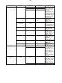
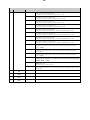
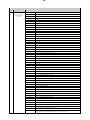
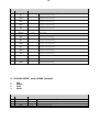
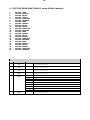
10- RDM FUNCTIONS
RDM ADDITIONAL MESSAGEs:
CURVE
CURVE DESCRIPTION
1
1: LINEAR
2
2: QUADRATIC (default)
3
3: S-CURVE
4
4: GAMMA 2.2
OUTPUT RESPONSE TIME
OUTPUT_RESPONSE_TIME_DESCRIPTION
0
0: SMOOTH OFF
1
1: SMOOTH 1 ( 25 ms)
2
2: SMOOTH 2 ( 50 ms)
3
3: SMOOTH 3 ( 75 ms)
4
4: SMOOTH 4 (100 ms) (default)
5
5: SMOOTH 5 (125 ms)
6
6: SMOOTH 6 (150 ms)
7
7: SMOOTH 7 (175 ms)
8
8: SMOOTH 8 (200 ms)
9
9: SMOOTH 9 (225 ms)
10
10: SMOOTH 10 (250 ms)
11
11: SMOOTH 11 (275 ms)
12
12: SMOOTH 12 (300 ms)
13
13: SMOOTH 13 (325 ms)
14
14: SMOOTH 14 (350 ms)
15
15: SMOOTH 15 (375 ms)
16
16: SMOOTH 16 (400 ms)
17
17: SMOOTH 17 (425 ms)
18
18: SMOOTH 18 (450 ms)
19
19: SMOOTH 19 (475 ms)
20
20: SMOOTH 20 (500 ms)

19
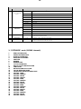
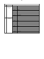
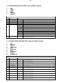
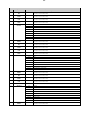
10- RDM FUNCTIONS
RDM ADDITIONAL MESSAGEs:
MODULATION FREQUENCY
MODULATION FREQUENCY DESCRIPTION
1
1: 610 Hz
2
2: 800 Hz
3
3: 1000 Hz (default)
4
4: 1500 Hz
5
5: 2000 Hz
6
6: 2500 Hz
7
7: 3000 Hz
8
8: 3500 Hz
9
9: 4000 Hz
10
10: 4500 Hz
11
11: 5000 Hz
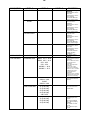
RDM MANUFACTURER-SPECIFIC PIDs:
MANUFACTURER-SPECIFIC PID
DESCRIPTION
LED PIXEL INVERT
0 = Disabled (default)
1 = Enabled
FANS SETTING
0 = Fan mode Standard (default)
1 = Fan mode Silent
2 = Fan mode Ultra-Silent
3 = Fan mode Auto
DISPLAY STANDBY
0 = DISABLED (Default)
1 = ENABLED
2 = FORCED ENABLED
NO DMX ACTION
1 = BLACKOUT
2 = PROGRAM 1-16
3 = RGB 100%
4 = RGB 60%
5 = CUSTOM
6 = CUSTOM2
7 = CUSTOM3
8 = CUSTOM4
9 = KEEP LAST (default)

20
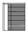
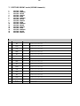
RDM MANUFACTURER-SPECIFIC PIDs:
MANUFACTURER-SPECIFIC PID
DESCRIPTION
RED NO DMX
Range 0-255 (Default = 128)
GREEN NO DMX
Range 0-255 (Default = 128)
BLUE NO DMX
Range 0-255 (Default = 128)
WHITE NO DMX
Range 0-255 (Default = 128)
INT NO DMX
Range 0-255 (Default = 128)
RED FINE NO DMX
Range 0-255 (Default = 128)
GREEN FINE NO DMX
Range 0-255 (Default = 128)
BLUE FINE NO DMX
Range 0-255 (Default = 128)
WHITE FINE NO DMX
Range 0-255 (Default = 128)
INT FINE NO DMX
Range 0-255 (Default = 128)
RED2 NO DMX
Range 0-255 (Default = 128)
GREEN2 NO DMX
Range 0-255 (Default = 128)
BLUE2 NO DMX
Range 0-255 (Default = 128)
WHITE2 NO DMX
Range 0-255 (Default = 128)
INT2 NO DMX
Range 0-255 (Default = 128)
RED2 FINE NO DMX
Range 0-255 (Default = 128)
GREEN2 FINE NO DMX
Range 0-255 (Default = 128)
BLUE2 FINE NO DMX
Range 0-255 (Default = 128)
WHITE2 FINE NO DMX
Range 0-255 (Default = 128)
INT2 FINE NO DMX
Range 0-255 (Default = 128)
RED3 NO DMX
Range 0-255 (Default = 128)
GREEN3 NO DMX
Range 0-255 (Default = 128)
BLUE3 NO DMX
Range 0-255 (Default = 128)
WHITE3 NO DMX
Range 0-255 (Default = 128)
INT3 NO DMX
Range 0-255 (Default = 128)
RED3 FINE NO DMX
Range 0-255 (Default = 128)
GREEN3 FINE NO DMX
Range 0-255 (Default = 128)
BLUE3 FINE NO DMX
Range 0-255 (Default = 128)
WHITE3 FINE NO DMX
Range 0-255 (Default = 128)
INT3 FINE NO DMX
Range 0-255 (Default = 128)
RED4 NO DMX
Range 0-255 (Default = 128)
GREEN4 NO DMX
Range 0-255 (Default = 128)
BLUE4 NO DMX
Range 0-255 (Default = 128)
WHITE4 NO DMX
Range 0-255 (Default = 128)
INT4 NO DMX
Range 0-255 (Default = 128)
RED4 FINE NO DMX
Range 0-255 (Default = 128)
GREEN4 FINE NO DMX
Range 0-255 (Default = 128)
BLUE4 FINE NO DMX
Range 0-255 (Default = 128)
WHITE4 FINE NO DMX
Range 0-255 (Default = 128)
INT4 FINE NO DMX
Range 0-255 (Default = 128)
La pagina si sta caricando...
La pagina si sta caricando...
La pagina si sta caricando...
La pagina si sta caricando...
La pagina si sta caricando...
La pagina si sta caricando...
La pagina si sta caricando...
La pagina si sta caricando...
La pagina si sta caricando...
La pagina si sta caricando...
La pagina si sta caricando...
La pagina si sta caricando...
La pagina si sta caricando...
La pagina si sta caricando...
La pagina si sta caricando...
La pagina si sta caricando...
La pagina si sta caricando...
La pagina si sta caricando...
La pagina si sta caricando...
La pagina si sta caricando...
La pagina si sta caricando...
La pagina si sta caricando...
La pagina si sta caricando...
La pagina si sta caricando...
La pagina si sta caricando...
La pagina si sta caricando...
La pagina si sta caricando...
La pagina si sta caricando...
La pagina si sta caricando...
La pagina si sta caricando...
La pagina si sta caricando...
La pagina si sta caricando...
La pagina si sta caricando...
La pagina si sta caricando...
La pagina si sta caricando...
La pagina si sta caricando...
La pagina si sta caricando...
La pagina si sta caricando...
La pagina si sta caricando...
La pagina si sta caricando...
-
 1
1
-
 2
2
-
 3
3
-
 4
4
-
 5
5
-
 6
6
-
 7
7
-
 8
8
-
 9
9
-
 10
10
-
 11
11
-
 12
12
-
 13
13
-
 14
14
-
 15
15
-
 16
16
-
 17
17
-
 18
18
-
 19
19
-
 20
20
-
 21
21
-
 22
22
-
 23
23
-
 24
24
-
 25
25
-
 26
26
-
 27
27
-
 28
28
-
 29
29
-
 30
30
-
 31
31
-
 32
32
-
 33
33
-
 34
34
-
 35
35
-
 36
36
-
 37
37
-
 38
38
-
 39
39
-
 40
40
-
 41
41
-
 42
42
-
 43
43
-
 44
44
-
 45
45
-
 46
46
-
 47
47
-
 48
48
-
 49
49
-
 50
50
-
 51
51
-
 52
52
-
 53
53
-
 54
54
-
 55
55
-
 56
56
-
 57
57
-
 58
58
-
 59
59
-
 60
60


DTS X-BRICK Manuale utente
- Categoria
- Proiettori
- Tipo
- Manuale utente
- Questo manuale è adatto anche per
in altre lingue
- English: DTS X-BRICK User manual
Documenti correlati
-
 DTS Brick Manuale utente
-
 DTS SCENA LED 80 FR FC Manuale utente
-
 DTS Portfolio Manuale utente
-
 DTS SCENA LED 120 HQS Manuale utente
-
 DTS EUPHONY 3 Manuale utente
-
 DTS DRIVENET 1664 Manuale utente
-
 DTS Katana Manuale utente
-
 DTS F-25 Manuale utente
-
 DTS FOS 100 FULL RGBW Manuale utente
-
 DTS DELTA 12 HEAD Manuale utente


Altri documenti
-
 Lampo DIODE ONE Full Colour Manuale utente
-
ProLights ECLPANELTWC Manuale utente
-
Cameo S2 IP Manuale utente
-
-
Coemar PinLite Led T Instructions Manual
-
-
-
FOS Cyclone RGB II Manuale utente
-
SDJ SG WECONBOX Manuale utente
-
 STUDIO DUE SLIMBAR FLAT RGBW 50cm Manuale utente

