Victron energy 12-250 Manuale utente
- Categoria
- Adattatori di alimentazione
- Tipo
- Manuale utente

Manual
EN
Handleiding
NL
Manuel
FR
Anleitung
DE
Manual
ES
Manuale
IT
Phoenix Inverter VE.Direct
12 | 250 12 | 375 12 | 500 12 | 800 12 | 1200
24 | 250 24 | 375 24 | 500 24 | 800 24 | 1200
48 | 250 48 | 375 48 | 500 48 | 800 48 | 1200

1
EN NL FR DE ES IT
1. IMPORTANT SAFETY INSTRUCTIONS – SAVE
THESE INSTRUCTIONS!
In general
Please read the documentation supplied with this product first, so that you are familiar with the
safety signs en directions before using the product.
This product is designed and tested in accordance with international standards. The equipment
should be used for the designated application only.
Warning – These servicing instructions are for use by qualified
personnel only. To reduce the risk of electric shock, do not
perform any servicing other than that specified in the operating
instructions unless you are qualified to do so.
WARNING: ELECTRIC SHOCK HAZARD
The product is used in conjunction with a permanent energy source (battery). Input and/or output
terminals may still be dangerously energized, even when the equipment is switched off. Always
disconnect the battery before carrying out maintenance or servicing the product.
The product has no internal user-serviceable components. Do not remove the front plate or
operate the product if any panels have been removed. All servicing must be undertaken by
qualified personnel.
Please read the installation instructions in the installation manual before installing the equipment.
This is a Safety Class I product (supplied with a protective grounding terminal). The chassis must
be grounded. A grounding point is located on the outside of the product. Whenever it is likely that
the grounding protection has been damaged, the product must be turned off and secured against
unintended operation; please contact qualified service staff.
The AC output is isolated from the DC input and the chassis unless the unit is equipped with a
Ground Fault Circuit Interrupter (GFCI). Units with a GFCI have AC output neutral
connected to chassis inside the device by default. A qualified installer should check this
connection since it is necessary for the GFCI to function properly. Local regulations may
require a true neutral. In this case one of the AC output wires must be connected to the chassis,
and the chassis must be connected to a reliable ground. Please note that a true neutral is
needed to ensure correct operation of an earth leakage circuit breaker.
Ensure that the equipment is used under the correct ambient conditions.
Never operate the product in a wet or dusty environment.
Never use the product where there is a risk of gas or dust explosions.
Ensure there is adequate free space (10 cm) for ventilation around the product and check that the
ventilation vents are not blocked.
This appliance is not intended for use by persons (including children) with reduced physical,
sensory or mental capabilities, or lack of experience and knowledge, unless they have been
given supervision or instruction concerning use of the appliance by a person responsible for
their safety.
Children should be supervised to ensure that they do not play with the appliance.
Use of an attachment not recommended or sold by the marine unit manufacturer may result in a
risk of fire, electric shock, or injury to persons.

2
2. Description
VE.Direct communication port
The VE.Direct port can be connected to:
• A computer (VE.Direct to USB interface cable needed)
• Apple and Android smartphones, tablets and other devices (VE.Direct to Bluetooth Smart
dongle needed)
Fully configurable
• Low battery voltage alarm trip and reset levels
• Low battery voltage cut-off and restart levels, or Dynamic Cut-off
• Output voltage 210 - 245 V
• Frequency 50 Hz or 60 Hz
• ECO mode on/off and ECO mode sense level
Monitoring
Battery voltage, AC Output voltage, load indicator, alarms
Proven reliability
The full bridge with toroidal transformer topology has proven its reliability over many years.
The inverters are short circuit proof and protected against overheating, whether due to overload or
high ambient temperature.
High start-up power
Needed to start loads such as power converters for LED lamps, filament lamps or electric tools.
ECO mode
When in ECO mode, the inverter will switch to standby when the load decreases below a preset
value. It will switch on and check every few seconds, adjustable, if the load has increased again.
Remote on/off connector
A remote on/off switch can be connected to a two-pole connector or between battery plus and the
left hand contact of the two pole connector.
LED diagnosis
A red and a green LED indicate inverter operation and status of the different protections.
To transfer the load to another AC source: the automatic transfer switch
For our low power inverters we recommend our Filax Automatic Transfer Switch. The Filax
features a very short switchover time (less than 20 milliseconds) so that computers and other
electronic equipment will continue to operate without disruption.
Available with different output sockets
Schuko, UK (BS-1363), AU/NZ (3112) or IEC-320 (male plug included)

3
EN NL FR DE ES IT
3. Installation
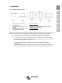
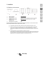
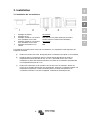
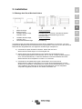
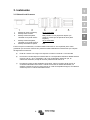
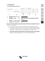
3.1 Location of the inverter
1
Ceiling mounting (inverted).
Not recommended
2.
Base mounting.
OK
3
Vertical wall mounting, fan at
bottom.
OK (beware of small objects falling through the
ventilation openings on top).
4
Vertical wall mounting, fan on top.
Not recommended
5
Horizontal wall mounting.
OK
For best operating results, the inverter should be placed on a flat surface. To ensure a trouble free
operation of the inverter, it must be used in locations that meet the following requirements:
a) Avoid any contact with water. Do not expose the inverter to rain or moisture.
b) Do not place the unit in direct sunlight. Ambient air temperature should be between
-20 °C and 40 °C (humidity < 95 % non condensing). Note that in extreme situations the
inverter’s case temperature can exceed 70 °C.
c) Do not obstruct the airflow around the inverter. Leave at least 10 centimetres
clearance
around the inverter. When the inverter is running too hot, it will shut down. When the
inverter has reached a safe temperature level the unit will automatically restart again.

4
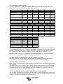
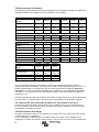
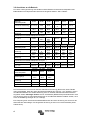
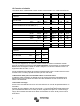
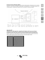
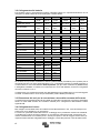
3.2 Connection to the battery
In order to utilize the full capacity of the product, batteries with sufficient capacity and battery
cables with sufficient cross section should be used. See table:
12/250
24/250
48/250
12/375
24/375
48/375
Minimum battery cap.
30 Ah
20 Ah
10 Ah
40 Ah
30 Ah
15 Ah
Internal DC fuse 2 x 30 A 30 A 25 A 2 x 40 A 40 A 25 A
Fuse type
ATOF
32 V
ATOF
32 V
FKS
80 V
ATOF
32 V
ATOF
32 V
FKS
80 V
Fuse replaceble no no no no no no
Recommended DC cable cross-section (mm2)
0 – 1,5 m
4 mm²
2,5 mm²
1,5 mm²
6 mm²
4 mm²
2,5 mm²
1,5 – 3 m
6 mm²
4 mm²
2,5 mm²
10 mm²
6 mm²
4 mm²
12/500
24/500
48/500
12/800
24/800
48/800
Minimum battery cap.
60 Ah
40 Ah
20 Ah
100 Ah
50 Ah
30 Ah
Internal DC fuse
3 x 35 A
2 x 25 A
30 A
150 A
80 A
40 A
Fuse type
ATOF
32 V
ATOF
32 V
FKS
80 V
BF1
32 V
BF1
32 V
BF1
58 V
Fuse replaceble
no
no
no
yes
yes
yes
Recommended DC cable cross-section (mm2)
0 – 1,5 m
6 mm²
6 mm²
4 mm²
16 mm²
6 mm²
4 mm²
1,5 -3 m
10 mm²
10 mm²
6 mm²
25 mm²
10 mm²
6 mm²
12/1200
24/1200
48/1200
Minimum battery cap.
150 Ah
60 Ah
30 Ah
Internal DC fuse
200 A
125 A
60 A
Fuse type
BF1
32 V
BF1
32 V
BF1
58 V
Fuse replaceble
yes
yes
yes
0 – 1,5 m
25 mm²
10 mm²
6 mm²
1,5 -3 m
35 mm²
16 mm²
10 mm²
The inverters are fitted with an internal DC fuse (see table above for rating). If the DC cable length
is increased to more than 1,5m, an additional fuse or DC circuit breaker must be inserted close to
the battery. Important note: for UL certified (NEMA GFCI) inverters it is mandatory to install a
fuse or DC circuit breaker close to the battery, even if the cable length is less than 1,5m.
Reverse polarity connection of the battery wires will blow the internal fuse and can damage the
inverter. The internal fuse is not always replaceble (see table above).
3.3 Wire size for connecting the inverter chassis to ground
The earth conductor from the earth lug on the chassis to ground should have at least half the
cross-section of the conductors used for the battery connection: see Appendix B.
3.4 Connection to the load
Never connect the output of the inverter to another AC source, such as a household AC wall outlet
or a generator.
The inverter does not have a fuse in the AC output. The AC cabling is protected by a fast-acting
current limiter in case of a short circuit and an overload detection mechanism which mimics the
characteristics of a fuse (i.e. faster shutdown with larger overload). It is important to size your
wiring properly based on the inverters’ power rating.
3.5 Connecting the inverter neutral output to the chassis/ground
The AC output is isolated from the DC input and the chassis. Local regulations may require a true
neutral. In this case one of the AC output wires must be connected to the chassis, and the chassis
must be connected to a reliable ground: see appendix A.

5
EN NL FR DE ES IT
3.6 Remote on/off connector
A remote on/off switch can be connected to the two-pole connector. Alternatively, the left-hand
contact of the connector can be switched to battery positive: useful in automotive applications,
wire it to the ignition contact.
Note that also the front switch needs to set to either On or ECO for the inverter to start.
3.7 Configuration
The inverter is ready for use with the factory settings (see specifications), and can be configured
with a computer (VE.Direct to USB interface cable needed), Apple and Android smartphones,
tablets and other devices (VE.Direct to Bluetooth Smart dongle needed).

6
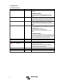
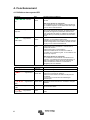
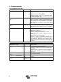
4. Operation
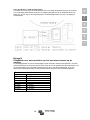
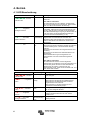
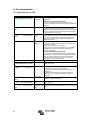
4.1 LED definitions
Green LED
Status
Trouble shooting
●●●●●●●●
Solid on
Inverter on
Red LED Off
status OK
Red LED On or blinking:
The Inverter is still on, but will shut down when the
condition gets worse. See red LED table for warning
reason
●●------
Slow single pulse
ECO mode
If the inverter keeps switching on and off while there is a
load connected, the load may be too small compared to the
actual ECO mode settings. Increase the load or change
ECO mode settings. (minimum ECO mode setting: 15 W)
●-●----- Fast double pulse
Off and waiting
Inverter did shut down because of a protection. The
inverter will restart automatically as soon as all alarm
conditions are cleared. See red LED state for the shutdown
reason.
--------
Off
Inverter off
Red LED Off
Check the On/Off/ECO switch: it should be in On position
or in ECO position.
Check Remote on/off connector.
Check DC cable connections and fuses.
Inverter fuse blown: the inverter has to be returned for
service.
Red LED On or blinking
The inverter did shut down because of a protection. It will
no longer automatically restart. The red LED indicates the
reason for shutdown. Remove the cause and then restart
the inverter by switching it Off, and then back On.
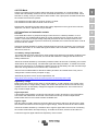
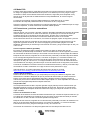
Red LED
Definition
Trouble shooting
●●●●●●●● Solid on
Overload
Reduce load
●●●●----
Slow blink
Low batt.
Recharge or replace battery
Check DC cable connections
Check cable cross section as it may be insufficient.
See section 4.3 Protections and automatic restarts for
manual and automatic restart behavior.
●-●-●-●- Fast blink
High batt.
Reduce DC input voltage, check for faulty charger
●-●----- Double pulse
High temp.
Reduce load and/or move inverter to better ventilated area
●---●---
Fast single pulse
High DC ripple
Check DC cable connections and cable cross section.

7
EN NL FR DE ES IT
4.2 ECO Mode
Set the front switch to ECO mode to reduce the power consumption in no-load operation. The
inverter will automatically switch off as soon as it detects that there is no load connected. It then
switches on, briefly, every 2.5 seconds to detect a load. If the output power exceeds the set level,
the inverter will continue to operate.
The default ECO mode wake-up minimum power is 15 Watt.
The default ECO mode search interval is 2.5 seconds
Note that the required ECO mode settings are heavily dependent on the type of load: inductive,
capacitive, non-linear. Adjustment may be needed.
4.3 Protections and automatic restarts
Overload
Some loads like motors or pumps draw large inrush currents in a start-up situation. In such
circumstances, it is possible that the start-up current exceeds the over current trip level of the
inverter. In this case the output voltage will quickly decrease to limit the output current of the
inverter. If the over current trip level is continuously exceeded, the inverter will shut down: wait 30
seconds and then restart.
After three restarts followed by another overload within 30 seconds of restarting, the inverter will
shutdown and remain off. The LEDs will signal shutdown due to overload. To restart the inverter,
switch it Off, then On.
Low battery voltage (adjustable)
The inverter will shut down when the DC input voltage drops below the low battery shutdown level.
After a minimum delay of 30 seconds, the inverter will restart if the voltages rise above the low
battery restart level.
After three restarts followed by a low battery shutdown within 30 seconds of restarting, the inverter
will shutdown and stop retrying. The LEDs will signal low battery shutdown. To restart the inverter,
switch it Off, and then On, or recharge the battery: as soon as the battery has risen and then stays
above the Charge detect level for 30 seconds, it will switch on.
See the Technical Data table for default low battery shutdown and restart levels. They can be
changed with VictronConnect (computer or app).
Alternatively Dynamic Cut-off can be implemented, see
https://www.victronenergy.com/live/ve.direct:phoenix-inverters-dynamic-cutoff
High battery voltage
Reduce DC input voltage and/or check for a faulty battery- or solar-charger in the system. After
shutting down due to a high battery voltage, the inverter will first wait 30 seconds and then retry
operation as soon as the battery voltage has dropped to acceptable level. The inverter will not
stay off after multiple retries.
High temperature
A high ambient temperature or enduring high load may result in shut down to over temperature.
The inverter will restart after 30 seconds. The inverter will not stay off after multiple retries.
Reduce load and/or move inverter to better ventilated area.
High DC ripple
High DC ripple is usually caused by loose DC cable connections and/or too thin DC wiring. After
the inverter has switched off due to high DC ripple voltage, it waits 30 seconds and then restarts.
After three restarts followed by a shutdown due to high DC ripple within 30 seconds of restarting,
the inverter will shutdown and stops retrying. To restart the inverter, switch it Off and then On.
Continuous high DC ripple reduces life expectancy of the inverter.

8
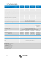
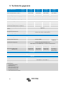
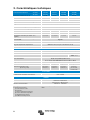
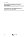
5. Technical data
Phoenix Inverter
12 Volt
24 Volt
48 Volt
12/250
24/250
48/250
12/375
24/375
48/375
12/500
24/500
48/500
12/800
24/800
48/800
Cont. power at 25 °C (1)
250 VA
375 VA
500 VA
800 VA
Cont. power at 25 °C / 40 °C
200 / 175 W
300 / 260 W
400 / 350 W
650 / 560 W
Peak power
400 W
700 W
900 W
1500 W
Output AC voltage / frequency (adjustable)
230 VAC or 120 VAC +/- 3 % 50 Hz or 60 Hz +/- 0.1 %
Input voltage range
9.2 - 17 / 18.4 - 34.0 / 36.8 - 62.0 VDC
Low battery shut down (adjustable)
9.3 / 18.6 / 37.2 VDC
Low battery restart & alarm (adjustable)
10.9 / 21.8 / 43.6 VDC
Battery charged detect (adjustable)
14.0 / 28.0 / 56.0 VDC
Max. efficiency
87/88/88 %
89/89/90 %
90/90/91 %
90/90/91 %
Zero-load power
4.2/5.2/7.9 W
5.6/6.1/8.5 W
6/6.5/9 W
6.5/7/9.5 W
Default zero-load power in ECO mode
(default search interval: 2.5 s, adjustable)
0.8/1.3/2.5 W 0.9/1.4/2.6 W 1 / 1.5 / 3 W 1 / 1.5 / 3 W
ECO mode stop and start power setting
Adjustable
Protection (2)
a – f
Operating temperature range
-40 to +60 °C (fan assisted cooling)
(derate 1.25 % per °C above 40 °C)
Humidity (non-condensing)
max 95 %
ENCLOSURE
Material & Colour
Steel chassis and plastic cover (blue Ral 5012)
Battery-connection
Screw terminals
Maximum cable cross-section 10 mm² / AWG8
25/10/10 mm² /
AWG4/8/8
Standard AC outlets
230 V: Schuko (CEE 7/4), IEC-320 (male plug included)
UK (BS 1363), AU/NZ (AS/NZS 3112)
120 V: Nema5-15R, NEMA GFCI (2x Nema5-15R with GFCI)
Protection category
IP 21
Weight
2.4 kg/5.3 lbs
3.0 kg/6.6 lbs
3.9 kg/8.5 lbs
5.5 kg/12 lbs
Dimensions (hxwxd, mm)
(hxwxd, inch)
86x165x260
3.4x6.5x10.2
86x165x260
3.4x6.5x10.2
86x172x275
3.4x6.8x10.8
105x216x305
4.1x8.5x12.1
(12 V model:
105x230x325)
ACCESSORIES
Remote on-off
Yes
Automatic transfer switch
Filax or Multi
STANDARDS
Safety
EN/IEC 60335-1 / EN/IEC 62109-1 / UL 458 (3)
EMC
EN 55014-1 / EN 55014-2
IEC 61000-6-1 / IEC 61000-6-3
Automotive Directive
ECE R10-4 EN 50498
1) Nonlinear load, crest factor 3:1
2) Protection key:
a) output short circuit
b) overload
c) battery voltage too high
d) battery voltage too low
e) temperature too high
f) DC ripple too high
3) UL 458 only for inverters with GFCI output socket

9
EN NL FR DE ES IT
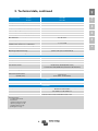
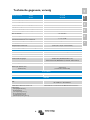
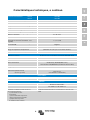
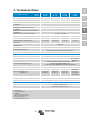
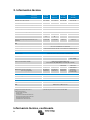
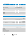
5. Technical data, continued
Phoenix Inverter
12 Volt
24 Volt
48 Volt
12/1200
24/1200
48/1200
Cont. power at 25 °C (1)
1200 VA
Cont. power at 25 °C / 40 °C
1000 / 900 W
Peak power
2200 W
Output AC voltage / frequency (adjustable)
230 VAC or 120 VAC +/- 3 % 50 Hz or 60 Hz +/- 0.1 %
Input voltage range
9.2 - 17 / 18.4 - 34.0 / 36.8 - 62.0 VDC
Low battery shut down (adjustable)
9.3 / 18.6 / 37.2 VDC
Low battery restart & alarm (adjustable)
10.9 / 21.8 / 43.6 VDC
Battery charged detect (adjustable)
14.0 / 28.0 / 56.0 VDC
Max. efficiency
92 / 94 / 94 %
Zero-load power
8 / 9.5 / 10 W
Default zero-load power in ECO mode
(default search interval: 2.5 s, adjustable)
1 / 1.7 / 2.7 W
ECO mode stop and start power setting
Adjustable
Protection (2)
a – f
Operating temperature range
-40 to +60 °C (fan assisted cooling)
(derate 1.25 % per °C above 40 °C)
Humidity (non-condensing)
max 95 %
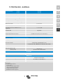
ENCLOSURE
Material & Colour
Steel chassis and plastic cover (blue Ral 5012)
Battery-connection
Screw terminals
Maximum cable cross-section
35/25/25 mm² / AWG2/4/4
Standard AC outlets
230 V: Schuko (CEE 7/4), IEC-320 (male plug included)
UK (BS 1363), AU/NZ (AS/NZS 3112)
120 V: Nema5-15R, NEMA GFCI (2x Nema5-15R with GFCI)
Protection category
IP 21
Weight
7.7 kg/17 lbs
Dimensions (hxwxd, mm)
(hxwxd, inch)
117x232x327
4.6x9.1x12.9
(12 V model: 117x232x367)
ACCESSORIES
Remote on-off
Yes
Automatic transfer switch
Filax or Multi
STANDARDS
Safety
EN/IEC 60335-1 / EN/IEC 62109-1 / UL 458 (3)
EMC
EN 55014-1 / EN 55014-2
IEC 61000-6-1 / IEC 61000-6-3
Automotive Directive
ECE R10-4 EN 50498
1) Nonlinear load, crest factor 3:1
2) Protection key:
a) output short circuit
b) overload
c) battery voltage too high
d) battery voltage too low
e) temperature too high
f) DC ripple too high
3) UL 458 only for inverters with GFCI output socket

10
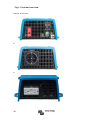
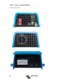
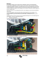
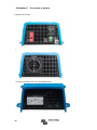
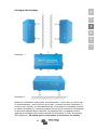
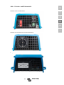
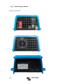
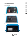
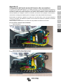
Fig 1: Front and rear view
FigFi
Example of front view:
Example of rear view with Schuko outlet:
Example of rear view with NEMA GFCI outlet:

11
EN NL FR DE ES IT
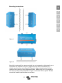
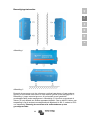
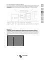
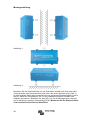
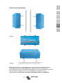
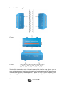
Mounting instructions
Figure 1
Figure 2
Mount the inverter with four screws vertically up- or downwards or horizontally up- or
downwards (as indicated in Figure 1) against a sturdy wall or horizontally on a
suitable ground surface (as indicated in Figure 2). Keep at least 4 inches (10 cm)
clearance with respect to other apparatus/objects. Beware that IP21 only applies to
the lower mounting method depicted in Figure 2; otherwise IP20 is applies. Do not
mount the inverter upside down to a surface.

12
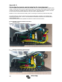
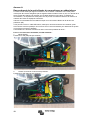
Appendix A
Connecting the inverter neutral output to the chassis/ground
The AC output is isolated from the DC input and the chassis. Local regulations may require a true
neutral. In this case one of the AC output wires must be connected to the chassis, and the chassis
must be connected to a reliable ground. Inside the inverter a provision has been made to be able
to connect the neural and the chassis; the way to do this is explained below.
Please be sure to disconnect the battery when connecting the neutral to protective earth (PE).
An internal PE wire, which is used to connect the neutral and the chassis, is accessible after
removing the plastic cover. A Torx T10 screwdriver is needed to loosen the four screws which
hold the plastic cover.
In the pictures below the two possible connections of the PE wire are shown:
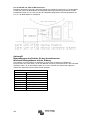
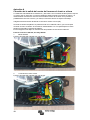
For the 250 VA, 375 VA and 500 VA inverters:
1. Neutral floating
Position of the PE wire (indicated by arrow):
2. Neutral connected to protective earth
Position of the PE wire (indicated by arrow):

13
EN NL FR DE ES IT
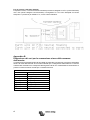
For the 800 VA and 1200 VA inverters:
For these inverters the earth wire from the chassis can be either connected to FJ1 (neutral
floating) or to FJ2 (neutral connected to earth/chassis). The labels FJ1 and FJ2 are printed on the
circuit board. The default position is FJ1, i.e. neutral is floating.
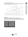
Appendix B
Wire size for connecting the inverter chassis to ground
The earth conductor from the earth lug on the chassis to ground should have at least half the
cross-section of the conductors used for the battery connection. The maximum conductor size that
fits the earth lug is 25 mm². Use the table below to find the correct cross-section for the earth
conductor.
Cable cross-section
to battery
to protective earth
1.5 mm²
≥ 0.75 mm²
2.5 mm²
≥ 1.5 mm²
4 mm²
≥ 2.5 mm²
6 mm²
≥ 4 mm²
10 mm²
≥ 6 mm²
16 mm²
≥ 10 mm²
25 mm²
≥ 16 mm²
35 mm²
25 mm²


1
EN NL FR DE ES IT
1. BELANGRIJKE VEILIGHEIDSINSTRUCTIES –
BEWAAR DEZE INSTRUCTIES!
In het algemeen
Lees eerst de documentatie die bij dit product wordt geleverd, zodat u bekend bent met de
veiligheidstekens en aanwijzingen voordat u het product gebruikt.
Dit product is ontworpen en getest in overeenstemming met internationale normen. De apparatuur
mag alleen voor de aangewezen toepassing worden gebruikt.
Waarschuwing - Deze onderhoudsinstructies zijn alleen
bedoeld voor gebruik door gekwalificeerd personeel. Om het
risico van elektrische schokken te verminderen, mag u geen
ander onderhoud uitvoeren dan aangegeven in de
gebruiksaanwijzing, tenzij u daartoe gekwalificeerd bent.
WAARSCHUWING: KANS OP ELEKTRISCHE SCHOKKEN
Het product wordt gebruikt in combinatie met een permanente energiebron (accu). Zelfs als de
apparatuur is uitgeschakeld, kan een gevaarlijke elektrische spanning optreden bij de in en/of
uitgangsklemmen. Koppel altijd de accu los om onderhoud of reparaties uit te voeren aan het
product.
Het product bevat geen interne onderdelen die door de gebruiker kunnen worden onderhouden.
Verwijder het voorpaneel niet en stel het product niet in werking als niet alle panelen zijn
gemonteerd. Alle onderhoudswerkzaamheden dienen door gekwalificeerd personeel te worden
uitgevoerd.
Lees de installatievoorschriften in de installatiehandleiding voordat u de apparatuur installeert.
Dit is een product uit veiligheidsklasse I (dat wordt geleverd met een aardklem ter beveiliging). De
behuizing moet worden geaard. Aan de buitenkant van het product bevindt zich een aardpunt. Als
het aannemelijk is dat de aardbeveiliging is beschadigd, moet het product worden uitgeschakeld
en worden beveiligd tegen onbedoelde inbedrijfstelling; neem in dat geval contact op met
gekwalificeerd onderhoudspersoneel.
De AC-uitgang is geïsoleerd van de DC-ingang en het chassis, tenzij de unit is uitgerust met
een aardlekschakelaar (GFCI). Units met een GFCI hebben de neutraal van de AC-uitgang
standaard aan de binnenkant op het chassis aangesloten. Een gekwalificeerde installateur
moet deze aansluiting controleren, aangezien deze noodzakelijk is voor de goede werking
van de GFCI. Afhankelijk van de plaatselijke voorschriften kan een echte neutrale geleider vereist
zijn. In dat geval moet één van de AC-uitgangsdraden worden verbonden met het chassis en
moet het chassis worden verbonden met een betrouwbare aarding. Opmerking: een echte
neutrale geleider is vereist om ervoor te zorgen dat een aardlekschakelaar goed werkt.
Zorg ervoor dat de apparatuur wordt gebruikt in de juiste omgevingsvoorwaarden.
Gebruik het product nooit in een vochtige of stoffige omgeving.
Gebruik het product nooit als er kans is op gas- of stofexplosies.
Zorg ervoor dat er voldoende vrije ruimte is (10 cm) rondom het product voor ventilatie en dat de
ventilatieopeningen niet geblokkeerd zijn.
Dit apparaat is niet bedoeld voor gebruik door personen (inclusief kinderen) met verminderde
fysieke, zintuiglijke of mentale mogelijkheden, of gebrek aan ervaring en kennis, tenzij onder
toezicht of instructie betreffende het gebruik van het apparaat door een verantwoordelijke voor
hun veiligheid.
Zorg ervoor dat kinderen niet met dit apparaat spelen.
Gebruik van een hulpstuk dat niet door de fabrikant van de maritieme unit wordt aanbevolen of
verkocht, kan leiden tot brand, elektrische schokken of verwondingen van personen

2
2. Beschrijving
VE.Direct-communicatiepoort
De VE.Direct-poort kan worden aangesloten op:
• een computer (VE.Direct-naar-USB-interfacekabel vereist)
• Apple- en Android-smartphones, tablets en overige apparaten ('VE.Direct Bluetooth Smart
dongle vereist)
Volledig configureerbaar
• Schakel- en resetniveaus alarm voor lage accuspanning
• Niveaus voor het uitschakelen of opnieuw opstarten bij lage accuspanning, of Dynamisch
uitschakelen
• Uitgangsspanning 210 - 245 V
• Uitgangsfrequentie 50 Hz of 60 Hz
• ECO-modus aan/uit, ECO-modusdetectieniveau en ECO-moduszoekinterval
Bewaking
Accuspanning, AC-uitgangsspanning, laadindicator, alarmen
Bewezen betrouwbaarheid
De volledige brug met ringkern transformator topologie heeft zijn betrouwbaarheid al vele jaren
bewezen.
De omvormers zijn bestand tegen kortsluiting en beschermd tegen oververhitting, ongeacht of dit
wordt veroorzaakt door overbelasting of een hoge omgevingstemperatuur.
Hoog opstartvermogen
Benodigd om belastingen te starten, zoals vermogen-omvormers voor LED lampen,
gloeidraadlampen of elektrisch gereedschap.
ECO-modus
In de ECO-modus schakelt de omvormer over naar stand-by als de belasting onder een
vooringestelde waarde daalt. Om de paar seconden, dit is instelbaar, wordt de omvormer
ingeschakeld en controleert deze om de paar seconden, ook instelbaar, of de belasting weer is
gestegen.
Stekker voor in- of uitschakelen op afstand
Een schakelaar voor in-/uitschakelen op afstand kan worden aangesloten op een tweepolige
stekker of tussen de pluspool van de accu en het linker contact van de tweepolige stekker.
LED diagnose
Een rood en een groen LED lampje geven aan dat de omvormer in bedrijf is en geven de status
van de verschillende beveiligingen aan.
Automatische omschakelaar
Om de belasting op een andere AC-bron over te dragen is er de automatische omschakelaar
Voor de omvormers met een laag stroomverbruik adviseren wij onze Filax automatische
omschakelaar. De Filax heeft een zeer korte omschakeltijd (minder dan 20 milliseconden), zodat
computers en andere elektronische apparatuur kan blijven functioneren zonder onderbreking.
Beschikbaar met verschillende uitgangsstekkerbussen
Schuko, UK (BS-1363), AU/NZ (3112) of IEC-320 (inclusief mannetjesstekker)

3
EN NL FR DE ES IT
3. Installatie
3.1 Plaatsing van de omvormer
1
Plafond montage
Niet aanbevolen
2
Vloer montage
OK
3
Verticale muur montage,
ventilator onder
OK (pas op kleine objecten die door de ventilatie
openingen aan de bovenkant kunnen vallen)
4
Verticale muur montage,
ventilator boven
Niet aanbevolen
5
Horizontale muur montage
OK
Om een probleemloze werking van de omvormer te kunnen garanderen, moet de locatie waarin
deze wordt geïnstalleerd aan de volgende eisen voldoen:
a) Vermijdt elk contact met water. Stel de omvormer niet bloot aan regen of mist.
b) Plaats de omvormer niet in direct zonlicht. De omgevingstemperatuur moet tussen
-20 °C en 40 °C liggen (luchtvochtigheid < 95 % niet condenserend). In extreme
situaties kan de behuizing van de omvormer een temperatuur bereiken van meer dan
70 °C.
c) Vermijd obstructie van de luchtstroming rond de omvormer.
Laat minstens 10 centimeter ruimte vrij rond de omvormer. Wanneer de omvormer een
te hoge temperatuur heeft bereikt, zal deze zichzelf uitschakelen. Als de omvormer is
afgekoeld tot een acceptabele temperatuur schakelt deze weer in.

4
3.2 Aansluiting op de accu
Om de volledige capaciteit van het product te kunnen benutten, dient uitsluitend gebruik te worden
gemaakt van accu’s met voldoende capaciteit en van accukabels met de juiste doorsnede. Zie
tabel:
12/250
24/250
48/250
12/375
24/375
48/375
Min. accucapaciteit
30 Ah
20 Ah
10 Ah
40 Ah
30 Ah
15 Ah
Interne DC-zekering
2 x 30 A
30 A
25 A
2 x 40 A
40 A
25 A
Zekeringstype
ATOF
32 V
ATOF
32 V
FKS
80 V
ATOF
32 V
ATOF
32 V
FKS
80 V
Zekering vervangbaar
nee
nee
nee
nee
nee
nee
Aanbevolen DC-kabel Doorsnede (mm2)
0 – 1,5 m
4 mm²
2,5 mm²
1,5 mm²
6 mm²
4 mm²
2,5 mm²
1,5 – 3 m
6 mm²
4 mm²
2,5 mm²
10 mm²
6 mm²
4 mm²
12/500
24/500
48/500
12/800
24/800
48/800
Min. accucapaciteit
60 Ah
40 Ah
20 Ah
100 Ah
50 Ah
30 Ah
Interne DC-zekering
3 x 35 A
2 x 25 A
30 A
150 A
80 A
40 A
Zekeringstype
ATOF
32 V
ATOF
32 V
FKS
80 V
BF1
32 V
BF1
32 V
BF1
58 V
Zekering vervangbaar
nee
nee
nee
ja
ja
ja
Aanbevolen DC-kabel Doorsnede (mm2)
0 – 1,5 m
6 mm²
6 mm²
4 mm²
16 mm²
6 mm²
4 mm²
1,5 -3 m
10 mm²
10 mm²
6 mm²
25 mm²
10 mm²
6 mm²
12/1200
24/1200
48/1200
Min. accucapaciteit.
150 Ah
60 Ah
30 Ah
Interne DC-zekering
200 A
125 A
60 A
Zekeringstype
BF1
32 V
BF1
32 V
BF1
58 V
Zekering vervangbaar
ja
ja
ja
0 – 1,5 m
25 mm²
10 mm²
6 mm²
1,5 -3 m
35 mm²
16 mm²
10 mm²
De omvormers zijn uitgerust met een interne DC-zekering (zie de tabel hierboven voor de
nominale waarde). Als de DC-kabel langer wordt dan 1,5 m, moet een extra zekering of DC-
stroomonderbreker dicht bij de accu worden geplaatst. Belangrijke opmerking: voor UL-
gecertificeerde (NEMA GFCI) omvormers is het verplicht een zekering of DC-stroomonderbreker
dicht bij de accu te installeren, zelfs als de kabellengte minder dan 1,5 m bedraagt.
Als de accukabels met omgekeerde polariteit worden aangesloten, brandt de interne zekering
door en kan de omvormer beschadigd raken. De interne zekering is niet altijd vervangbaar (zie
tabel hierboven).
3.3 Draaddoorsnede voor het verbinden van het omvormerchassis met de aarde
De aardgeleider die van het aardingslipje op het chassis naar de grond leidt, moet een doorsnede
hebben die ten minste half zo groot is als die van de geleiders die worden gebruikt voor de
accuverbinding: zie bijlage B.
3.4 Aansluiting op de belasting
Sluit de uitgang van de omvormer nooit aan op een andere AC-bron, zoals een AC-stopcontact
voor huishoudelijk gebruik of een stroomgenerator.
De omvormer heeft geen zekering in de AC-uitgang. De AC-bekabeling wordt beschermd door
een snelwerkende stroombegrenzer in geval van kortsluiting en een
overbelastingsdetectiemechanisme dat de kenmerken van een zekering nabootst (d.w.z. snellere
uitschakeling bij grotere overbelasting). Het is belangrijk dat u de bedrading de juiste dikte heeft
op basis van het vermogen van de omvormer.

5
EN NL FR DE ES IT
3.5 Het aansluiten van de nuluitgang van de omvormer op het chassis/aarde
De AC-uitgang is geïsoleerd van de DC-ingang en het chassis. Lokale voorschriften vereisen
mogelijk een werkelijk nuluitgang. In dit geval moet een van de AC-uitgangsdraden op het chassis
worden aangesloten en moet het chassis op een betrouwbare aarde zijn aangesloten: zie bijlage
A
3.6 Stekker voor in- of uitschakelen op afstand
Een schakelaar voor in- of uitschakelen op afstand kan worden aangesloten op de tweepolige
stekker. Of het linker contact van de stekker kan worden omgezet naar de positieve accuklem:
handig in automobieltoepassingen, verbind dit dan met het ontstekingscontact.
Opmerking: ook de schakelaar aan de voorkant moet op On of ECO staan, anders start de
omvormer niet.
3.7 Configuratie
De omvormer is klaar voor gebruik met de fabrieksinstellingen (zie specificaties) en kan worden
geconfigureerd met een computer ('VE.Direct-naar-USB-interfacekabel vereist), Apple- en
Android-smartphones, tablets en overige apparaten ('VE.Direct Bluetooth Smart dongle vereist).
La pagina si sta caricando...
La pagina si sta caricando...
La pagina si sta caricando...
La pagina si sta caricando...
La pagina si sta caricando...
La pagina si sta caricando...
La pagina si sta caricando...
La pagina si sta caricando...
La pagina si sta caricando...
La pagina si sta caricando...
La pagina si sta caricando...
La pagina si sta caricando...
La pagina si sta caricando...
La pagina si sta caricando...
La pagina si sta caricando...
La pagina si sta caricando...
La pagina si sta caricando...
La pagina si sta caricando...
La pagina si sta caricando...
La pagina si sta caricando...
La pagina si sta caricando...
La pagina si sta caricando...
La pagina si sta caricando...
La pagina si sta caricando...
La pagina si sta caricando...
La pagina si sta caricando...
La pagina si sta caricando...
La pagina si sta caricando...
La pagina si sta caricando...
La pagina si sta caricando...
La pagina si sta caricando...
La pagina si sta caricando...
La pagina si sta caricando...
La pagina si sta caricando...
La pagina si sta caricando...
La pagina si sta caricando...
La pagina si sta caricando...
La pagina si sta caricando...
La pagina si sta caricando...
La pagina si sta caricando...
La pagina si sta caricando...
La pagina si sta caricando...
La pagina si sta caricando...
La pagina si sta caricando...
La pagina si sta caricando...
La pagina si sta caricando...
La pagina si sta caricando...
La pagina si sta caricando...
La pagina si sta caricando...
La pagina si sta caricando...
La pagina si sta caricando...
La pagina si sta caricando...
La pagina si sta caricando...
La pagina si sta caricando...
La pagina si sta caricando...
La pagina si sta caricando...
La pagina si sta caricando...
La pagina si sta caricando...
La pagina si sta caricando...
La pagina si sta caricando...
La pagina si sta caricando...
La pagina si sta caricando...
La pagina si sta caricando...
La pagina si sta caricando...
La pagina si sta caricando...
La pagina si sta caricando...
La pagina si sta caricando...
-
 1
1
-
 2
2
-
 3
3
-
 4
4
-
 5
5
-
 6
6
-
 7
7
-
 8
8
-
 9
9
-
 10
10
-
 11
11
-
 12
12
-
 13
13
-
 14
14
-
 15
15
-
 16
16
-
 17
17
-
 18
18
-
 19
19
-
 20
20
-
 21
21
-
 22
22
-
 23
23
-
 24
24
-
 25
25
-
 26
26
-
 27
27
-
 28
28
-
 29
29
-
 30
30
-
 31
31
-
 32
32
-
 33
33
-
 34
34
-
 35
35
-
 36
36
-
 37
37
-
 38
38
-
 39
39
-
 40
40
-
 41
41
-
 42
42
-
 43
43
-
 44
44
-
 45
45
-
 46
46
-
 47
47
-
 48
48
-
 49
49
-
 50
50
-
 51
51
-
 52
52
-
 53
53
-
 54
54
-
 55
55
-
 56
56
-
 57
57
-
 58
58
-
 59
59
-
 60
60
-
 61
61
-
 62
62
-
 63
63
-
 64
64
-
 65
65
-
 66
66
-
 67
67
-
 68
68
-
 69
69
-
 70
70
-
 71
71
-
 72
72
-
 73
73
-
 74
74
-
 75
75
-
 76
76
-
 77
77
-
 78
78
-
 79
79
-
 80
80
-
 81
81
-
 82
82
-
 83
83
-
 84
84
-
 85
85
-
 86
86
-
 87
87


Victron energy 12-250 Manuale utente
- Categoria
- Adattatori di alimentazione
- Tipo
- Manuale utente
in altre lingue
- français: Victron energy 12-250 Manuel utilisateur
- español: Victron energy 12-250 Manual de usuario
- Deutsch: Victron energy 12-250 Benutzerhandbuch
- Nederlands: Victron energy 12-250 Handleiding
Documenti correlati
-
Victron energy Inverter VE.Direct 250VA - 1200VA Manuale del proprietario
-
Victron energy Phoenix Manuale utente
-
Victron energy 12 | 250 Pure Sine Wave Phoenix Inverter Manuale utente
-
-
-
-
-
Victron energy 12-2000 230V Manuale utente
-
-