Victron energy 12-2000 230V Manuale utente
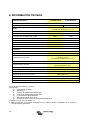
- Tipo
- Manuale utente

Manual
EN
Handleiding
NL
Manuel
FR
Anleitung
DE
Manual
ES
Användarhandbok
SE
Manuale
IT
Appendix
Phoenix Inverter Compact
12 | 2000 230V
24 | 2000 230V


1
EN NL FR DE ES SE IT Appendix
1. SAFETY INSTRUCTIONS
General
Please familiarize yourself with the safety features and instructions by first reading the
documentation supplied with this product before using the equipment. This product has
been designed and tested in accordance with international standards. The equipment
must be used exclusively for the purpose for which it was designed.
WARNING: ELECTRIC SHOCK HAZARD.
The product is used in conjunction with a permanent energy source (battery). Input and/or
output terminals may still be dangerously energized, even when the equipment is
switched off. Always switch off the AC supply and the battery before carrying out
maintenance or servicing the product.
The product has no internal user-serviceable components. Do not remove the front plate
or operate the product if any panels have been removed. All servicing must be undertaken
by qualified personnel.
Never use the product where there is a risk of gas or dust explosions. Consult the battery
manufacturer's information to ascertain that the product is intended for use in conjunction
with the battery. Always comply with the battery manufacturer's safety instructions.
WARNING: Do not lift heavy loads without assistance.
Installation
Read the installation instructions in the installation manual before installing the
equipment.
This is a Safety Class I product (supplied with a protective grounding terminal). The
chassis must be grounded. A grounding point is located on the outside of the product.
Whenever it is likely that the grounding protection has been damaged, the product must
be turned off and secured against unintended operation; please contact qualified service
staff.
Ensure that the DC and AC input cables are fused and fitted with circuit breakers. Never
replace a safety component with a different type. Consult the manual to determine the
correct component.
Before applying power, ensure that the available power source matches the configuration
settings of the product as described in the manual.
Ensure that the equipment is used under the correct ambient conditions. Never operate
the product in a wet or dusty environment. Ensure there is adequate free space for
ventilation around the product and check that the ventilation vents are not blocked.
Ensure that the required system voltage does not exceed the product's capacity.

2
Transport and Storage
Ensure that the mains power and battery leads have been disconnected before storing or
transporting the product.
No liability can be accepted for any transport damage if the equipment is shipped in non-
original packaging.
Store the product in a dry environment; the storage temperature must be between -20 °C
and 60 °C.
Consult the battery manufacturer's manual in respect of transport, storage, charging,
recharging and disposal of the battery.

3
EN NL FR DE ES SE IT Appendix
2. DESCRIPTION
2.1 General
SinusMax - Superior engineering
Developed for professional duty, the Phoenix range of inverters is suitable for the widest
range of applications. The design criteria have been to produce a true sine wave inverter
with optimised efficiency but without compromise in performance. Employing hybrid HF
technology, the result is a top-quality product with compact dimensions, light in weight
and capable of supplying power, problem-free, to any load.
Extra start-up power
A unique feature of the SinusMax technology is very high start-up power. Conventional
high frequency technology does not offer such extreme performance. Phoenix inverters,
however, are well suited to power up difficult loads such as compressors, electric motors
and similar appliances.
Parallel and 3-phase operation capability
Up to 6 inverters can operate in parallel to achieve higher power output.
Operation in 3-phase configuration is also possible.
To transfer the load to another AC source: the automatic transfer switch
If an automatic transfer switch is required, we recommend to using the MultiPlus or
Quattro instead. The switch is included in these products and the charger function of the
MultiPlus/Quattro can be disabled. Computers and other electronic equipment will
continue to operate without disruption because the MultiPlus/Quattro features a very short
switchover time (less than 20 milliseconds).
Programmable relay
The Phoenix Inverter is equipped with a programmable relay, which by default is set as
an alarm relay. The relay can be programmed for all kinds of other applications however,
for example as a starter relay for a generating set.
Programmable with DIP switches, VE.Net panel or personal computer
The Phoenix Inverter is supplied ready for use. Three features are available for changing
certain settings if desired:
- The most important settings can be changed in a very simple manner, using DIP
switches.
- All settings, with exception of the programmable relay, can be changed with a VE.Net
panel.
- All settings can be changed with a PC and free of charge software, downloadable from
our website www.victronenergy.com.

4
3. OPERATION
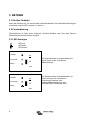
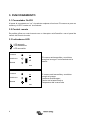
3.1 On/Off Switch
When switched to “on”, the product is fully functional. The inverter will come into operation
and the LED “inverter on” will light up.
3.2 Remote control
Remote control is possible with a simple on/off switch or with a Phoenix Inverter Control
panel.
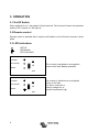
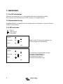
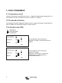
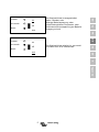
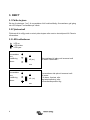
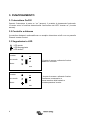
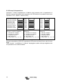
3.3 LED Indications
LED off
LED flashes
LED illuminated
The inverter is switched on and supplies
power to the load. Battery operation.
inverter
on
eco mode
off
alarm
eco
The inverter is switched on and supplies
power to the load.
Pre alarm: overload, or
battery voltage low, or
inverter temperature high
inverter
on
eco mode
off
alarm
eco

5
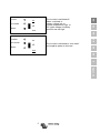
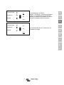
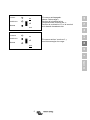
EN NL FR DE ES SE IT Appendix
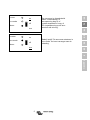
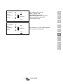
The inverter is switched off.
Alarm: overload, or
battery voltage low, or
inverter temperature high, or
DC ripple voltage on battery
terminal was too high.
inverter
on
eco mode
off
alarm
eco
The inverter is switched on “eco mode”
and supplies power to the load.
inverter
on
eco mode
off
alarm
eco

6
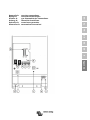
4. INSTALLATION
4.1 Location
The product must be installed in a dry and well-ventilated area, as close as possible to
the batteries. There should be a clear space of at least 10cm around the appliance for
cooling.
Excessively high ambient temperature will result in the following:
Reduced service life.
Reduced charging current.
Reduced peak capacity, or shutdown of the inverter.
Never mount the appliance directly above the batteries.
The product is suitable for wall mounting. For mounting see appendix A.
The appliance can be mounted horizontally as well as vertically; vertical mounting is
preferable. The vertical position offers optimum cooling.
Try and keep the distance between the product and the battery to a minimum in order to
minimize cable voltage losses.
For safety purposes, this product should be installed in a heat-resistant
environment if it is used with equipment where a substantial amount of
power is to be converted. You should prevent the presence of e.g.
chemicals, synthetic components, curtains or other textiles, etc., in the
immediate vicinity.
This product should be installed by a qualified electrician.
The interior of the product must remain accessible after installation.

7
EN NL FR DE ES SE IT Appendix
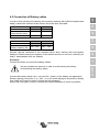
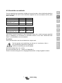
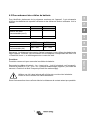
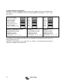
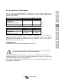
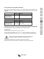
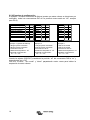
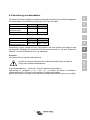
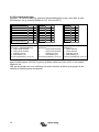
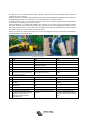
4.2 Connection of Battery cables
In order to fully utilize the full capacity of the product, batteries with sufficient capacity and
battery cables with sufficient cross section should be used. See table.
24/2000
12/2000
Recommended
cross section (mm
2
)
6 m
50
70
24/2000
12/2000
Recommended
battery capacity (Ah)
200 – 500 350 – 1000
Remark: Internal resistance is the important factor when working with low-capacity
batteries. Please consult your supplier or the relevant sections of our book “electricity on
board”, downloadable from our website.
Procedure
Proceed as follows to connect the battery cables:
Connect the battery cables: the + (red) and the - (black), to the battery see appendix A.
Reverse polarity connection (+ to – and – to +) will cause damage to the product. (Safety
fuse inside the Phoenix Inverter Compact can be damaged)
Secure the nuts tightly in order to reduce the contact resistance as much as possible.
Use an insulated box spanner in order to avoid shorting the battery.
Avoid shorting the battery cables.

8
4.3 Connection of the AC cabling
This is a Safety Class I product (supplied with a protective grounding
terminal).
The neutral wire of the AC output of this inverter is connected to
the chassis.
This is to ensure proper functioning of a GFCI (or RCCB) to be installed
in the AC output of the Inverter.
The chassis of the product must be connected toground, to the frame (of
a vehicle) or the ground plate or hull (of a boat).
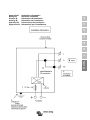
Procedure
The terminal points are indicated clearly. From left to right: “PE” (earth), “L” (phase) and
“N” (neutral).
4.4 Optional Connections
A number of optional connections are possible:
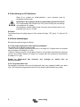
4.4.1 Remote on/off switch & remote Control panel
The product can be remotely controlled in two ways.
- With an external switch (connection terminal H, see appendix A). Operates only if the
switch on the Inverter is set to “on”.
- With a Phoenix Inverter Control panel (connected to one of the two RJ45 sockets C, see
appendix A). Operates only if the switch on the inverter is set to “on”.
Only one remote control can be connected, i.e. either a switch or a remote control
panel.
4.4.2. Programmable relay
The inverters are equipped with a multi-functional relay that by default is programmed as
an alarm relay. (VEConfigure3 software needed to change relay functionality).
Near the connection terminals an LED illuminates when the relay is activated (refer to S,
see appendix A).

9
EN NL FR DE ES SE IT Appendix
4.4.3 Parallel Connection
The inverters can be connected in parallel with several identical devices. To this end, a
connection is established between the devices by means of standard RJ45 UTP cables.
The system (one or more inverters plus optional control panel) will require subsequent
configuration (see Section 5).
In the event of connecting inverters in parallel, the following requirements must be met:
- A maximum of six units connected in parallel.
- Only identical devices may be connected in parallel.
- The DC connection cables to the devices must be of equal length and cross-section.
- If a positive and a negative DC distribution point is used, the cross-section of the connection between
the batteries and the DC distribution point must at least equal the sum of the required cross-sections
of the connections between the distribution point and the inverters.
- Place the inverters close to each other, but allow at least 10 cm for ventilation purposes under, above
and beside the units.
- UTP cables must be connected directly from one unit to the other (and to the remote panel).
Connection/splitter boxes are not permitted.
- Only one remote control means (panel or switch) can be connected to the system.
4.4.4 Three-phase operation
The Phoenix Inverter can also be used in 3-phase wye (Y) configuration. To this end, a
connection between the devices is made by means of standard RJ45 UTP cables (the
same as for parallel operation). The system (Inverters plus an optional control panel) will
require subsequently configuration (see Section 5).
Pre-requisites: see Section 4.4.3.
Note: the Phoenix Inverter is not suitable for 3-phase delta (Δ) configuration.

10
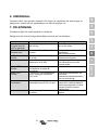
5. CONFIGURATION
5.1 Standard settings: ready for use
On delivery, the Phoenix inverter is set to standard factory values. In general, these
settings are suitable for stand-alone operation.
Standard factory settings
Inverter frequency 50 Hz
Inverter voltage 230 VAC
Stand-alone / parallel / 3-phase stand-alone
Search mode off
Programmable relay alarm function
5.2 Explanation of settings
Inverter frequency
Output frequency
Adjustability: 50 Hz; 60 Hz
Inverter voltage
Adjustability: 210 – 245 V
Stand-alone / parallel operation / 2-3 phase setting
Using several devices, it is possible to:
- Increase total inverter power (several devices in parallel).
- Create a split-phase system.
- Create a 3-phase system.
The standard product settings are for standalone operation. For parallel, three phase or
split phase operation see section 4.4.3 and 4.4.4.
Settings may only be changed by a qualified engineer.
Carefully read the instructions before changes are made.
Batteries should be placed in a dry and well-ventilated area during charging.

11
EN NL FR DE ES SE IT Appendix
Search Mode (Applicable in stand-alone configuration only)
If search mode is “on”, the power consumption in no-load operation is decreased by approx.
70 %. In this mode the Compact, when operating in inverter mode, is switched off in case
of no load or very low load, and switches on every two seconds for a short period. If the
output current exceeds a set level, the inverter will continue to operate. If not, the inverter
will shut down again.
The Search Mode can be set with a DIP switch.
The Search Mode “shut down” and “remain on” load levels can be set with VEConfigure3.
The standard settings are:
Shut down: 40 Watt (linear load).
Turn on: 100 Watt (linear load).
AES (Automatic Economy Switch)
Instead of the search mode, the AES mode can also be chosen (with help of VEConfigure3
only).
If this setting is turned “on”, the power consumption in no-load operation and with low loads
is decreased by approx. 20 %, by slightly “narrowing” the sinusoidal voltage.
Not adjustable with DIP switches.
Applicable in stand-alone configuration only.
Programmable relay
By default, the programmable relay is set as an alarm relay, i.e. the relay will de-energise
in the event of an alarm or a pre-alarm (inverter almost too hot, ripple on the input almost
too high, battery voltage almost too low).
Not adjustable with DIP switches.
Near the connection terminals an LED illuminates when the relay is activated (refer to S,
see appendix A).

12
5.3 Configuration by computer
All settings can be changed by means of a computer or with a VE.Net panel (except for
the multi-functional relay and the VirtualSwitch when using VE.Net).
Some settings can be changed with DIP switches (see Section 5.2).
For changing settings with the computer, the following is required:
- VEConfigure3 software: can be downloaded free of charge at www.victronenergy.com.
- A MK3-USB (VE.Bus to USB) interface.
Alternatively, the Interface MK2.2b (VE.Bus to RS232) can be used (RJ45 UTP cable
needed).
5.3.1 VE.Bus Quick Configure Setup
VE.Bus Quick Configure Setup is a software program with which one Compact unit or
systems with a maximum of three Compact units (parallel or three phase operation) can
be configured in a simple manner. VEConfigure3 forms part of this program.
The software free can be downloaded free of charge at www.victronenergy.com.
5.3.2 VE.Bus System Configurator
For configuring advanced applications and/or systems with four or more inverters,
VE.Bus System Configurator software must be used. The software can be downloaded
free of charge at www.victronenergy.com. VEConfigure3 forms part of this program.
5.4 Configuration with a VE.Net panel
To this end, a VE.Net panel and the VE.Net to VE.Bus converter are required.
With VE.Net you can set all parameters, with the exception of the multi-functional relay
and the VirtualSwitch.

13
EN NL FR DE ES SE IT Appendix
5.5 Configuration with DIP switches
Some settings can be changed with DIP switches
Procedure:
a) Turn the Compact on, preferably without load.
b) Set the dipswitches as required.
c) Store the settings by moving Dip switch 8 to “on” and back to “off”.
5.5.1. DIP switch 1 and 2
Default setting: to operate the product with the “On/Off/Charger Only” switch
ds 1: “off”
ds 2: “on”
The default setting is required when using the “On/Off/Charger Only” switch in the front
panel. This setting should also be used in setups with a GX device or VE.Bus Smart
dongle when no additional Digital Multi Control panel or VE.Bus BMS is connected.
When a Digital Multi Control panel or a VE.Bus BMS is included please refer to the
settings below.
Setting for remote operation with a Multi Control Panel or a VE.Bus BMS:
ds 1: “on”
ds 2: “off”
This setting is required when a Multi Control Panel and/or a VE.Bus BMS is connected.
The Multi Control panel must be connected to one of the two RJ45 sockets B, see
appendix A.
Setting for remote operation with a 3-way switch:
ds 1: “off”
ds 2: “off”
This setting is required when a 3-way switch is connected.
The 3-way switch must be wired to terminal L, see appendix A.
Only one remote control can be connected, i.e. either a switch or a remote control
panel.
In both cases the switch on the product itself should be “on”.

14
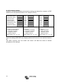
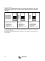
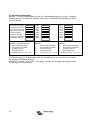
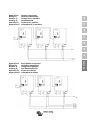
5.5.2 Exemplary settings
Example 1 is the factory setting (since factory settings are entered by computer, all DIP
switches of a new product are set to “off”, except for DS-2).
DS-1 Panel option
off
DS-2 Panel option
on
DS-3 Not used
DS-4 Not used
DS-5 Frequency
DS-6 Search mode
off
DS-7 Not used
DS-8 Store setting
→
←
DS-1
off
DS-2
on
DS-3
DS-4
DS-5
off
DS-6
off
DS-7
DS-8
→
←
DS-1
on
DS-2
off
DS-3
DS-4
DS-5
on
DS-6
on
DS-7
DS-8
→
←
Example 1: (factory setting)
1 No panel connected
2 No panel connected
5 Frequency: 50 Hz
6 Search mode off
8 store setting: off→ on→ off
Example 2
1 No panel connected
2 No panel connected
5 Frequency: 50 Hz
6 Search mode off
8 store setting: off→ on→ off
Example 3
1 Panel connected
2 Panel connected
5 Frequency: 60 Hz
6 Search mode on
8 store setting: off→ on→ off
Store the settings (DS3-DS7) by changing switch ds-8 from off to on, and then back to
off.
The LED’s “Inverter” and “eco mode” and “alarm” will flash four times to indicate
acceptance of the settings.

15
EN NL FR DE ES SE IT Appendix
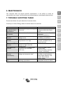
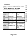
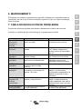
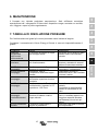
6. MAINTENANCE
The Compact does not require specific maintenance. It will suffice to check all
connections once a year. Avoid moisture and oil/soot/vapours, and keep the device clean.
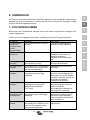
7. TROUBLE SHOOTING TABLE
Proceed as follows for quick detection of common faults.
Consult your Victron Energy dealer if the fault cannot be resolved.
Problem
Cause
Solution
The inverter fails
to operate when
switched on.
The battery voltage is too high
or too low.
Ensure that the battery
voltage is within the correct
value.
The inverter fails
to operate
Processor in no function-mode.
Switch Front switch off, wait
4 seconds
Switch front switch on.
The alarm LED
flashes.
Pre-alarm alt. 1: The DC input
voltage is low.
Charge the battery or check
the battery connections.
The alarm LED
flashes
Pre-alarm alt. 2: The ambient
temperature is too high.
Place the inverter in a cool
and well-ventilated room or
reduce the load.
The alarm LED
flashes.
Pre-alarm alt. 3: The load on the
inverter is higher than the
nominal load.
Reduce the load.
The alarm LED
flashes.
Pre-alarm alt. 4: Voltage ripple
on the DC input exceeds
1,25 Vrms.
Check the battery cables
and terminals.
Check the battery capacity;
increase if necessary.
The alarm LED
flashes
intermittantly.
Pre-alarm alt. 5. Low battery
voltage and excessive load.
Charge the batteries, reduce
the load or install batteries
with a higher capacity. Use
shorter and/or thicker
battery cables.
The alarm LED is
on
The inverter did cut out
following a pre-alarm.
Check the table for the
appropriate course of action.

16
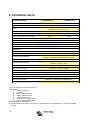
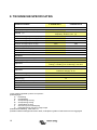
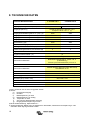
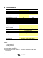
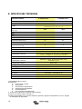
8. TECHNICAL DATA
1) Can be adjusted to 60 Hz and to 240 V
2) Protection
a) Output short circuit
b) Overload
c) Battery voltage too high
d) Battery voltage too low
e) Temperature too high
f) 230 VAC on inverter output
g) Input voltage ripple too high
3) Non linear load, crest factor 3:1
4) Programmable relay which can be set for general alarm, DC undervoltage or genset start signal
function
Phoenix Inverter C 12/2000 230 V C 24/2000 230 V
INVERTER
Input voltage range (VDC)
9,5 – 17 V
19 – 33 V
Output Output voltage: 230 VAC ± 2 %
Frequency: 50 Hz ± 0,1 % (1)
Cont. output power at 25 °C (VA) (3) 2000 2000
Cont. output power at 25 °C (W)
1600
1600
Cont. output power at 40 °C (W)
1450
1450
Cont. output power at 65 °C (W)
1000
1000
Peak power (W)
3500
3500
Maximum efficiency (%) 92 92
Zero-load power (W) 9 11
Zero load power in search mode (W) 3 4
GENERAL
Programmable relay (4)
yes
Protection (2)
a - g
Common Characteristics Operating temp. range: -40 to +65 °C (fan assisted
cooling) Humidity (non condensing): max 95%
ENCLOSURE
Common Characteristics Material & Colour: aluminium (blue RAL 5012)
Protection category: IP 21
Battery-connection
Bolts M8
230 VAC-connection
connector 6 mm², 10 AWG
Weight (kg)
12
Dimensions (hxwxd in mm)
520 x 255 x 125
STANDARDS
Safety EN 60335-1, EN 60335-2-29
Emission / Immunity EN 55014-1, EN 55014-2, EN 61000-3-3

1
EN NL FR DE ES SE IT Appendix
1.VEILIGHEIDSVOORSCHRIFTEN
Algemeen
Lees eerst de bij dit product geleverde documentatie, zodat u bekend bent met de
veiligheidsaanduidingen en aanwijzingen voordat u de apparatuur in gebruik neemt.
Dit product is ontworpen en getest overeenkomstig internationale normen. De apparatuur
dient uitsluitend voor de bestemde toepassing te worden gebruikt.
WAARSCHUWING: KANS OP ELEKTRISCHE SCHOKKEN.
Het product wordt gebruikt in combinatie met een permanente energiebron. (batterij) Zelfs
als de apparatuur is uitgeschakeld, kan een gevaarlijke elektrische spanning optreden bij
de in -en/ of uitgangsklemmen. Schakel altijd de wisselstroomvoeding en de batterij uit
voor het plegen van onderhoud.
Het product bevat geen interne onderdelen die door de gebruiker kunnen worden
onderhouden. Haal het paneel aan de voorkant er niet af en stel het product niet in
werking als niet alle panelen zijn gemonteerd. Al het onderhoud dient door gekwalificeerd
personeel te worden uitgevoerd.
Gebruik het product nooit op plaatsen waar gas -of stofexplosies kunnen optreden.
Raadpleeg de gegevens van de fabrikant van de batterij om u ervan te verzekeren dat
het product bestemd is voor gebruik in combinatie met de batterij. De
veiligheidsvoorschriften van de fabrikant van de batterij dienen altijd te worden
opgevolgd.
WAARSCHUWING: Til geen zware lasten zonder hulp.
Installatie
Lees de installatievoorschriften in de bedieningshandleiding voordat u de apparatuur
inschakelt.
Dit is een product uit veiligheidsklasse I. (dat wordt geleverd met een aardklem ter
beveiliging). Aan de buitenkant van het product bevindt zich een aardingspunt. Als
het aannemelijk is dat de aardbeveiliging is beschadigd, moet het product buiten werking
worden gesteld en worden beveiligd tegen iedere onopzettelijke inwerkingstelling; neem
contact op met gekwalificeerd onderhoudspersoneel.
Zorg ervoor dat de aansluitkabels zijn voorzien van zekeringen en stroomonderbrekers.
Vervang een beveiligingsonderdeel nooit door een ander Typ. Raadpleeg de handleiding
voor het juiste onderdeel.
Controleer voordat u het apparaat inschakelt, dat de beschikbare spanningsbron
overeenkomt met de configuratie-instellingen van het product zoals beschreven in de
handleiding.

2
Zorg ervoor dat de apparatuur onder de juiste bedrijfsomstandigheden wordt gebruikt.
Stel het product nooit in bedrijf in de regen of in een stoffige omgeving. Zorg ervoor dat
er altijd voldoende vrije ruimte rondom het product is voor ventilatie en dat de ventilatie-
openingen niet zijn geblokkeerd.
Verzeker u ervan dat de vereiste spanning niet hoger is dan de capaciteit van het product.
Vervoer en opslag
Zorg ervoor dat de netspanning en batterijkabels zijn losgekoppeld bij opslag of vervoer
van het product.
Er kan geen aansprakelijkheid worden aanvaard voor transportschade indien de
apparatuur wordt vervoerd in een andere dan de originele verpakking.
Sla het product op in een droge omgeving; de opslagtemperatuur moet tussen de –20 °C
en 60 °C liggen.
Raadpleeg de handleiding van de fabrikant van de batterij met betrekking tot vervoer,
opslag, opladen, herladen en verwijderen van de batterij.
La pagina sta caricando ...
La pagina sta caricando ...
La pagina sta caricando ...
La pagina sta caricando ...
La pagina sta caricando ...
La pagina sta caricando ...
La pagina sta caricando ...
La pagina sta caricando ...
La pagina sta caricando ...
La pagina sta caricando ...
La pagina sta caricando ...
La pagina sta caricando ...
La pagina sta caricando ...
La pagina sta caricando ...
La pagina sta caricando ...
La pagina sta caricando ...
La pagina sta caricando ...
La pagina sta caricando ...
La pagina sta caricando ...
La pagina sta caricando ...
La pagina sta caricando ...
La pagina sta caricando ...
La pagina sta caricando ...
La pagina sta caricando ...
La pagina sta caricando ...
La pagina sta caricando ...
La pagina sta caricando ...
La pagina sta caricando ...
La pagina sta caricando ...
La pagina sta caricando ...
La pagina sta caricando ...
La pagina sta caricando ...
La pagina sta caricando ...
La pagina sta caricando ...
La pagina sta caricando ...
La pagina sta caricando ...
La pagina sta caricando ...
La pagina sta caricando ...
La pagina sta caricando ...
La pagina sta caricando ...
La pagina sta caricando ...
La pagina sta caricando ...
La pagina sta caricando ...
La pagina sta caricando ...
La pagina sta caricando ...
La pagina sta caricando ...
La pagina sta caricando ...
La pagina sta caricando ...
La pagina sta caricando ...
La pagina sta caricando ...
La pagina sta caricando ...
La pagina sta caricando ...
La pagina sta caricando ...
La pagina sta caricando ...
La pagina sta caricando ...
La pagina sta caricando ...
La pagina sta caricando ...
La pagina sta caricando ...
La pagina sta caricando ...
La pagina sta caricando ...
La pagina sta caricando ...
La pagina sta caricando ...
La pagina sta caricando ...
La pagina sta caricando ...
La pagina sta caricando ...
La pagina sta caricando ...
La pagina sta caricando ...
La pagina sta caricando ...
La pagina sta caricando ...
La pagina sta caricando ...
La pagina sta caricando ...
La pagina sta caricando ...
La pagina sta caricando ...
La pagina sta caricando ...
La pagina sta caricando ...
La pagina sta caricando ...
La pagina sta caricando ...
La pagina sta caricando ...
La pagina sta caricando ...
La pagina sta caricando ...
La pagina sta caricando ...
La pagina sta caricando ...
La pagina sta caricando ...
La pagina sta caricando ...
La pagina sta caricando ...
La pagina sta caricando ...
La pagina sta caricando ...
La pagina sta caricando ...
La pagina sta caricando ...
La pagina sta caricando ...
La pagina sta caricando ...
La pagina sta caricando ...
La pagina sta caricando ...
La pagina sta caricando ...
La pagina sta caricando ...
La pagina sta caricando ...
La pagina sta caricando ...
La pagina sta caricando ...
La pagina sta caricando ...
La pagina sta caricando ...
La pagina sta caricando ...
La pagina sta caricando ...
La pagina sta caricando ...
La pagina sta caricando ...
-
 1
1
-
 2
2
-
 3
3
-
 4
4
-
 5
5
-
 6
6
-
 7
7
-
 8
8
-
 9
9
-
 10
10
-
 11
11
-
 12
12
-
 13
13
-
 14
14
-
 15
15
-
 16
16
-
 17
17
-
 18
18
-
 19
19
-
 20
20
-
 21
21
-
 22
22
-
 23
23
-
 24
24
-
 25
25
-
 26
26
-
 27
27
-
 28
28
-
 29
29
-
 30
30
-
 31
31
-
 32
32
-
 33
33
-
 34
34
-
 35
35
-
 36
36
-
 37
37
-
 38
38
-
 39
39
-
 40
40
-
 41
41
-
 42
42
-
 43
43
-
 44
44
-
 45
45
-
 46
46
-
 47
47
-
 48
48
-
 49
49
-
 50
50
-
 51
51
-
 52
52
-
 53
53
-
 54
54
-
 55
55
-
 56
56
-
 57
57
-
 58
58
-
 59
59
-
 60
60
-
 61
61
-
 62
62
-
 63
63
-
 64
64
-
 65
65
-
 66
66
-
 67
67
-
 68
68
-
 69
69
-
 70
70
-
 71
71
-
 72
72
-
 73
73
-
 74
74
-
 75
75
-
 76
76
-
 77
77
-
 78
78
-
 79
79
-
 80
80
-
 81
81
-
 82
82
-
 83
83
-
 84
84
-
 85
85
-
 86
86
-
 87
87
-
 88
88
-
 89
89
-
 90
90
-
 91
91
-
 92
92
-
 93
93
-
 94
94
-
 95
95
-
 96
96
-
 97
97
-
 98
98
-
 99
99
-
 100
100
-
 101
101
-
 102
102
-
 103
103
-
 104
104
-
 105
105
-
 106
106
-
 107
107
-
 108
108
-
 109
109
-
 110
110
-
 111
111
-
 112
112
-
 113
113
-
 114
114
-
 115
115
-
 116
116
-
 117
117
-
 118
118
-
 119
119
-
 120
120
-
 121
121
-
 122
122
-
 123
123
-
 124
124


Victron energy 12-2000 230V Manuale utente
- Tipo
- Manuale utente
in altre lingue
Documenti correlati
-
Victron energy Phoenix Inverter Compact 1200 1600 Manuale del proprietario
-
-
-
-
-
-
-
-
-