Eneo IEB-63F0037M0A Quick Installation Manual
- Categoria
- Telecamere di sicurezza
- Tipo
- Quick Installation Manual
Questo manuale è adatto anche per

EN
DE
FR
IT
Quick Installation Guide
1/2.8” Network Camera,
Day&Night, 2048x1536,
Infrared, 12VDC, PoE, IP67
IEB-63F0037M0A
IEB-63M2812M0A

2
Content
Components ................................................................................................................... 5
Installation .....................................................................................................................6
Installation ...........................................................................................................................................................................6
Installing and Adjusting Camera ............................................................................................................................6
Extension Cable ................................................................................................................................................................7
microSD Card Insertion ................................................................................................................................................... 8
Connections .......................................................................................................................................................................8
Connecting the Network ........................................................................................................................................... 8
Connecting Audio ....................................................................................................................................................... 8
Connecting Alarms ..................................................................................................................................................... 9
Connecting the Power ...............................................................................................................................................9
Network Connection & IP Assignment ................................................................................................................. 9
Resetting to the factory default settings .......................................................................................................... 11
Further information ...................................................................................................................................................... 12

3
EN
Safety instructions
General safety instructions
• Before switching on and operating the system, rst read this safety advice and the operating instructions.
• Keep the operating instructions in a safe place for later use.
• Installation, commissioning and maintenance of the system may only be carried out by authorised
individuals and in accordance with the installation instructions - ensuring that all applicable standards and
guidelines are followed.
• Protect the devices from water penetration and humidity, since these can cause lasting damage.
• Should moisture nevertheless enter the system, under no circumstance switch on the devices under these
conditions, instead send them for examination to an authorised specialist workshop.
• The system must never be used outside of the technical specications, since this can destroy it.
• The device must be protected from excesses of heat, dust, humidity and vibration.
• When separating the system from the voltage supply, only ever use the plug to pull out the cable. Never
pull directly on the cable itself.
• Lay the connecting cables carefully and check that they are not mechanically stressed, kinked or damaged
and that no humidity can penetrate into them.
• In the event of a malfunction, please inform your supplier.
• Maintenance and repairs may only be carried out by authorised specialist personnel.
• The system must be isolated from the power supply before opening the housing.
• The device may only be opened by qualied service personnel. Unauthorised access invalidates any
warranty claim.
• Connection cables should always be exchanged through Videor E. Hartig GmbH.
• Use only original spare parts and accessories from Videor E. Hartig GmbH.
• The housing should only be cleaned using a mild domestic cleaning agent. Never use solvents or petrol as
these can permanently damage the surface.
• During installation, it is essential to ensure that the seals provided are correctly installed and that they are
not displaced during installation. Damaged seals must not be installed and will invalidate any warranty.
• The installer is responsible for the maintenance of the enclosure as per the technical data, e.g. by sealing
the cable outlets with silicone.
• Wire end ferrules should be used when shortening the exible connection cables.
• The devices may only be operated in the temperature range indicated in the data sheet and within the
dened air humidity range.
Product - Specic Safety Instructions
• The camera may never be pointed directly at the Sun with the aperture open (this will destroy the sensor).
• It is unavoidable that during manufacture and to a certain extent during later use, humidity will be present
in the ambient air within the device’s housing. In the event of large temperature uctuations, this humidity
may condense inside the housing.
• To avoid this condensation inside the very tightly sealed housing, the manufacturer has inserted silica gel
sachets in the housing of the various camera types.
• It is however a physical given, that these silica gel bags will reach saturation after a certain amount of time.
They should therefore be replaced with new silica gel sachets.
• During installation, it is essential to ensure that the seals provided are correctly installed and that they are
not displaced during installation. Damaged seals must not be installed and will invalidate any warranty.
• A multipolar, easily accessible isolation device should be installed in the proximity of the IR Spotlight, in
order to disconnect the device from the power supply for service work.
• The earth connection must be made according to the low impedance requirement of DIN VDE 0100.
• Subsequent painting of the equipment surface can impair the function.
• Any warranty claim is invalidated by subsequent painting.
• A safety margin of > 1m from the spotlight must be maintained when viewing directly into the IR Spotlight
in a darkened environment.
• Do not look directly at invisible LED radiation using optical instruments (e.g. a reading glass, magnifying
glass or microscope), since this can endanger the eyes, LED Class 1M.
• Operation of the IR spotlight with a defective cover or during repair is prohibited.

4
Class A device note
This is a Class A device. This device can cause malfunctions in the living area; in such an event, the operator may
need to take appropriate measures to compensate for these.
WEEE (Waste Electronical & Electronic Equipment)
Correct Disposal of This Product (Applicable in the European Union and other European countries with separate
collection systems).
This marking shown on the product or its literature, indicates that it should not be disposed with
other household wastes at the end of its working life. To prevent possible harm to the environment
or human health from uncontrolled waste disposal, please separate this from other types of wastes
and recycle it responsibly to promote the sustainable reuse of material resources. Household users
should contact either the retailer where they purchased this product, or their local government
oce, for details of where and how they can take this item for environmentally safe recycling.
Business users should contact their supplier and check the terms and conditions of the purchase
contract. This product should not be mixed with other commercial wastes for disposal.
Graphical symbols
Please pay attention to the safety instructions, and carefully read through this instruction guide before initial
operation.
Important points of warning are marked with a caution symbol.
i
Important points of advice are marked with a notice symbol.

5
EN
Components
This system comes with the following components;
• Network Camera
• Installation Guide/CD
• Template Sheet
• Accessory Kit
NOTE: Adapter for 12 VDC is not supplied.

6
Installation
Installation
For the operation of the Network Camera, it is necessary to connect a network cable for
data transmission, power connection from supplied power adapter. Depending on opera-
tion methods, it is possible to connect an alarm cable additionally.
The network camera should be attached to a structural object, such as hard wood, wall
stud or ceiling rafter that supports the weight of the network camera. For its xation on
dierent locations, please consult with an installer.
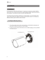
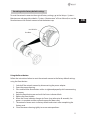
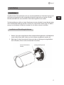
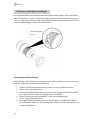
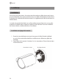
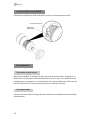
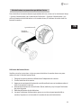
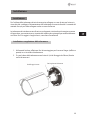
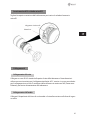
Installing and Adjusting Camera
1. Using the template sheet make mounting holes and cable hole in the place (ceil-
ing or wall) to which the camera is to be installed.
2. Fix the base of the camera with the three screws (20mm tapping screws) provided
in the accessory kit.
3x20 mm Tapping screws
Tension adjustment screw

7
EN
CAUTION: Adjusting the position of the camera after installation could potentially dam-
age the cable.
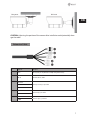
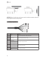
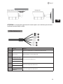
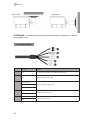
Extension Cable
No. Connector Description
1 RJ-45 Ethernet, RJ-45 port compatible with 10/100Mbps having PoE functionality
2 DC Jack Main Power, DC Jack, 12 VDC
3
AI: Alarm In
Alarm input and output, 3-pin terminal G: GND
AO: Alarm Out
4
MIC: Audio In
Audio line input, 2-pin terminal
G: GND
5
SPK: Audio Out
Audio line output, 2-pin terminal
G: GND
Wall mountCeiling mount

8
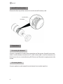
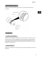
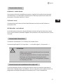
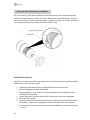
microSD Card Insertion
Remove the front cap of the camera to insert the microSD memory card.
Connections
Connecting the Network
Connect a standard RJ-45 cable to the network port of the camera. Generally a crossover
cable is used for directly connection to PC, while a direct cable is used for connection to a
hub. You can also use a router featuring PoE (Power over Ethernet) to supply power to the
camera.
Connecting Audio
Connect speaker to audio output line and external mic to audio input line.
Reset Button
microSD Card Slot

9
EN
Connecting Alarms
AI (Alarm In)
You can use external devices to signal the network camera to react on events. Mechanical
or electrical switches can be wired to the AI (Alarm In) and G (Ground) connectors.
G (Ground)
Connect the ground side of the alarm input and/or alarm output to the G (Ground)
connector.
AO (Alarm Out)
The network camera can activate external devices such as buzzers or lights. Connect the
device to the AO (Alarm Out) and G (Ground) connectors.
Connecting the Power
Connect power of 12VDC 450 mA for the network camera.
Connect the positive (+) pole to the ‘+’ position and the negative (-) pole to the ‘-’ position.
CAUTION:
• Be careful not to reverse the polarity when you connect
the power cable.
• You can also use a router featuring PoE (Power over Ether-
net) to supply power to the camera.
• If PoE and 12 VDC are both applied, the camera will be
supplied with the power from PoE.
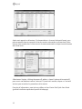
Network Connection & IP Assignment
The eneo scanning device tool is used to locate all eneo network cameras in a local net-
work. The tool does not need to be installed with a setup program. The program exe-le
can be started directly from the CD with a simple double click to use the program.

10
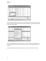
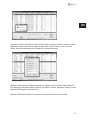
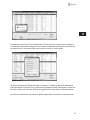
After pushing the button „Find eneo devices“ you will get a list of cameras connected to
the local network. Highlight your camera in the list and open a context menu with a click
of the right mouse button.
Select the „Editing the camera IP address“ option to open a window for setting the cam-
eras IP properties. When you are done click the „Activate“ button to update the camera
settings.
For further information, please refer to the eneo Scan Device Tool Quick Start Guide.

11
EN
Resetting to the factory default settings
To reset the network camera to the original factory settings, go to the Setup > System >
Maintenance web page (described in ”System > Maintenance” of Users Manual) or use the
Reset button on the network camera inside the bottom cap.
Using the Reset button:
Follow the instructions below to reset the network camera to the factory default settings
using the Reset button.
1. Switch o the network camera by disconnecting the power adapter.
2. Open the camera housing.
3. Press and hold the Reset button with a straightened paperclip while reconnecting
the power.
4. Keep the Reset button pressed until the Status indicator blinks.
5. Release the Reset button.
6. When the Power Indicator changes to Green (may take up to 40 seconds), the
process is complete and the network camera has been reset.
7. The network camera resets to factory default and restarts after completing the
factory reset.
8. Close the camera housing tightly to ensure waterproofness.
Reset Button
microSD Card Slot

12
CAUTION: When performing a Factory Reset, you will lose any settings that have been
saved. (Default IP 192.168.1.10)
Further information
Make sure to always upgrade to the latest rmware version available from the eneo web-
site at www.eneo-security.com to receive the latest functionality for your product.
The manual, and other software tools are available on the eneo website at www.eneo-se-
curity.com or on the included CD.
Information on compatible video management software solutions can be found in the
category Videomanagement at www.eneo-security.com.
Open Source Software
The software included in this product contains copyrighted software that is licensed
under open source licenses.
You may obtain the complete corresponding source code from eneo for a period of three
years after the last shipment of this product by sending email to: opensource@eneo-se-
curity.com.
If you want to obtain the complete corresponding source code with a physical medium
such as CD-ROM, the cost of physically performing source distribution might be charged.
For more details about Open Source Software, refer to the eneo website at www.eneo-se-
curity.com or an included product CD.

13
DE
Inhalt
Komponenten ..............................................................................................................16
Installation ...................................................................................................................17
Installation ........................................................................................................................................................................ 17
Installation und Einstellung der Kamera .......................................................................................................... 17
Verlängerungskabel ..................................................................................................................................................... 18
MicroSD-Karte einsetzen ............................................................................................................................................. 19
Anschlüsse ....................................................................................................................................................................... 19
Anschluss an das Netzwerk ................................................................................................................................... 19
Audio anschließen ................................................................................................................................................... 19
Anschließen von Alarmen ..................................................................................................................................... 20
Anschluss der Stromversorgung ........................................................................................................................ 20
Netzwerkverbindung und IP-Zuweisung ......................................................................................................... 20
Rücksetzen auf die Werkseinstellungen ........................................................................................................... 22
Weitere Informationen ................................................................................................................................................ 23

14
Sicherheitsanweisungen
Sicherheitshinweise allgemein
• Bevor Sie das System anschließen und in Betrieb nehmen, lesen Sie zuerst diese Sicherheitshinweise und
die Betriebsanleitung.
• Bewahren Sie die Betriebsanleitung sorgfältig zur späteren Verwendung auf.
• Montage, Inbetriebnahme und Wartung des Systems darf nur durch dafür autorisierte Personen vorgenom-
men und entsprechend den Installationsanweisungen - unter Beachtung aller mitgeltenden Normen und
Richtlinien - durchgeführt werden.
• Die Geräte gegen Eindringen von Wasser und Feuchtigkeit schützen, dies kann zu dauerhaften Schäden
führen.
• Sollte dennoch Feuchtigkeit eingedrungen sein, die Geräte nie unter diesen Bedingungen einschalten,
sondern zur Überprüfung an eine autorisierte Fachwerkstatt geben.
• Das System darf nie außerhalb der technischen Daten benutzt werden, da es zerstört werden kann.
• Das Gerät ist vor großer Hitze, Staub, Feuchtigkeit und Vibrationseinwirkung zu schützen.
• Um das System von der Versorgungsspannung zu trennen, ziehen Sie das Kabel nur am Stecker heraus.
Ziehen Sie nie direkt am Kabel.
• Verlegen Sie die Verbindungskabel sorgfältig und stellen Sie sicher, dass die Kabel nicht mechanisch bean-
sprucht, geknickt oder beschädigt werden und keine Feuchtigkeit eindringen kann.
• Falls Funktionsstörungen auftreten, benachrichtigen Sie bitte Ihren Lieferanten.
• Wartung und Reparaturen dürfen nur von autorisiertem Fachpersonal ausgeführt werden.
• Vor Önen des Gehäuses ist eine Netztrennung erforderlich.
• Das Gerät darf nur von qualiziertem Servicepersonal geönet werden. Fremdeingrie beenden jeden
Garantieanspruch.
• Anschlusskabel sollten immer nur durch VIDEOR E. Hartig GmbH ausgetauscht werden.
• Verwenden Sie nur Originalersatzteile und Original-Zubehör von Videor E. Hartig GmbH.
• Zur Reinigung der Gehäuse immer nur ein mildes Haushaltsmittel verwenden. Niemals Verdünner oder
Benzin benutzen, dies kann die Oberäche dauerhaft schädigen.
• Bei der Montage muss grundsätzlich darauf geachtet werden, dass vorhandene Dichtungen ordnungs-
gemäß eingesetzt und bei der Montage nicht verschoben werden. Beschädigte Dichtungen dürfen nicht
mehr verbaut werden und führen zum Erlöschen des Garantieanspruchs.
• Der Errichter ist für die Aufrechterhaltung der Schutzart lt. Techn. Daten verantwortlich, z.B. durch Abdich-
tung des Kabelaustritts mit Silikon.
• Bei Kürzung von exiblen Anschlussleitung sind Adernendhülsen zu verwenden.
• Die Geräte dürfen nur in den im Datenblatt angegebenen Temperaturbereiche und der denierten Umge-
bungsluftfeuchte betrieben werden.
Sicherheitshinweise produktbezogen:
• Die Kamera darf nie mit geöneter Blende direkt gegen die Sonne gerichtet werden (dies zerstört den
Sensor).
• Es lässt sich nicht vermeiden, dass im Rahmen der Fertigung und auch beim späteren Gebrauch in gewis-
sem Umfang Feuchtigkeit der Umgebungsluft im Gehäuse vorhanden ist. Bei starken Temperaturschwan-
kungen kann sich die Feuchtigkeit im Gehäuse niederschlagen.
• Um dies in dem sehr dicht abschließenden Gehäuse zu vermeiden, hat der Hersteller bei verschiedenen
Kameratypen Silicagel-Beutel in das Kameragehäuse eingelegt.
• Es ist eine physikalische Gegebenheit, dass diese Silicagel-Beutel nach einer gewissen Zeit eine Sättigung
erreichen. Sie sollten deshalb gegen neue Silicagel-Beutel ausgetauscht werden.
• Bei der Montage muss grundsätzlich darauf geachtet werden, dass vorhandene Dichtungen ordnungs-
gemäß eingesetzt und bei der Montage nicht verschoben werden. Beschädigte Dichtungen dürfen nicht
mehr verbaut werden und führen zum Erlöschen des Garantieanspruchs.
• In der Nähe des IR-Scheinwerfers ist eine vielpolige, leicht zugängliche Trennvorrichtung zu installieren, um
das Gerät bei Servicearbeiten frei schalten zu können.
• Die Schutzleiterverbindung muss nach DIN VDE 0100 entsprechend niederohmig ausgeführt werden.
• Nachträgliches Lackieren der Geräteoberäche kann die Funktion beeinträchtigen.
• Durch das Nachlackieren erlischt jeglicher Gewährleistungsanspruch.

15
DE
• Bei abgedunkelter Umgebung und direktem Blick in den IR-Scheinwerfer ist ein Sicherheitsabstand von > 1
m zum Scheinwerfer einzuhalten.
• Unsichtbare LED Strahlung nicht direkt mit optischen Instrumenten (z.B. Lupe, Vergrößerungsglas oder
Mikroskop) betrachten, da sie eine Augengefährdung verursachen kann, LED Klasse 1M.
• Der Betrieb des IR-Scheinwerfers bei defekter Abdeckung oder bei Reparatur ist untersagt.
Hinweis für Geräte der Klasse A
Dies ist ein Gerät der Klasse A. Dieses Gerät kann im Wohnbereich Funktionsstörungen verursachen; in diesem Fall
kann vom Betreiber verlangt werden, angemessene Maßnahmen durchzuführen und dafür aufzukommen.
WEEE-Richtlinie (Elektro- und Elektronik-Altgeräte)
Ordnungsgemäße Entsorgung dieses Produkts (Gilt für die Europäische Union und anderen Europäischen Länder
mit getrennten Sammelsystemen)
Dieses am Produkt oder in seiner Dokumentation gezeigte Symbol bedeutet, dass es am Ende
seiner Lebensdauer nicht mit dem Hausmüll entsorgt werden darf. Um eventuelle Umwelt- oder
Gesundheitsschäden durch unkontrollierte Abfallbeseitigung zu verhindern, dieses Gerät von
anderen Abfallarten trennen und ordnungsgemäß recyceln, um die nachhaltige Wiederverwen-
dung materieller Ressourcen zu fördern. Haushaltsanwender sollten entweder den Händler, bei
dem sie dieses Produkt gekauft haben, oder ihr örtliches Regierungsbüro kontaktieren, um
Einzelheiten darüber zu erfahren, wo und wie sie dieses Gerät umweltgerecht recyceln können.
Geschäftliche Anwender sollten sich an ihren Lieferanten wenden und die Bedingungen des
Kaufvertrags überprüfen. Dieses Produkt darf zur Entsorgung nicht mit anderen Unternehmensabfällen vermischt
werden.
Grasche Symbole
Bitte beachten Sie die Sicherheitshinweise und lesen Sie diese Anleitung vor Inbetriebnahme sorgfältig durch.
Wichtige Warnhinweise sind mit einem Achtung-Symbol gekennzeichnet.
i
Wichtige Hinweise sind mit einem Hinweis-Symbol gekennzeichnet.

16
Komponenten
Das System wird mit den folgenden Komponenten geliefert:
• Netzwerk Kamera
• Installationsanleitung/CD
• Bohrschablone
• Montageset
HINWEIS: Adapter für 12V DC ist nicht im Lieferumfang enthalten.

17
DE
Installation
Installation
Zum Betrieb der Netzwerkkamera müssen ein Netzwerkkabel zur Datenübertragung und
die Stromversorgung durch das mitgelieferte Netzteil angeschlossen werden. Je nach
Betriebsmethode kann ein zusätzliches Alarmkabel angeschlossen werden.
Die Netzwerkkamera sollte an einem Bauelement wie etwa Hartholz, einem Wandständer
oder Deckenbalken befestigt werden, welches das Gewicht der Kamera trägt. Zur Befesti-
gung an verschiedenen Standorten wenden Sie sich bitte an einen Installateur.
Installation und Einstellung der Kamera
1. Bohren Sie mit der mitgelieferten Bohrschablone Montagelöcher und Kabellöcher
an der Stelle (Wand oder Decke), an der die Kamera angebracht werden soll.
2. Befestigen Sie die Unterseite der Kamera mit den im Montageset mitgelieferten
drei Schrauben (20 mm selbstschneidende Schrauben).
3x20 mm selbstschneidende
Schrauben
Spannungseinstellungsschraube

18
ACHTUNG: Wenn Sie die Position der Kamera nach der Installation verändern, könnte das
Kabel möglicherweise beschädigt werden.
Verlängerungskabel
Nr. Anschluss Beschreibung
1 RJ-45 Ethernet, RJ-45 Port kompatibel mit 10/100Mbps, mit PoE Funktion.
2 Netzteilanschluss Hauptstromversorgung, Netzteilanschluss, 12 V DC
3
AI: Alarmeingang
Alarmeingang und -ausgang, 3-Pin Anschluss G: Masse
AO: Alarmausgang
4
MIC: Audioeingang
Audio-Line-Eingang, 2-Pin Anschluss
G: Masse
5
SPK: Audioausgang
Audio-Line-Ausgang, 2-Pin Anschluss
G: Masse
WandmontageDeckenmontage

19
DE
MicroSD-Karte einsetzen
Entfernen Sie die vordere Abdeckung der Kamera, um die MicroSD-Speicherkarte
einzulegen.
Anschlüsse
Anschluss an das Netzwerk
Schließen Sie ein Standard-RJ-45-Kabel an den Netzwerkanschluss der Kamera an. Zum
Anschluss an einen PC wird im Allgemeinen ein Crossover-Kabel verwendet, während
zum Anschluss an einen Hub ein direktes Kabel (Patch-Kabel) verwendet wird. Zur Ver-
sorgung der Kamera mit Strom kann auch ein Router mit der PoE-Funktion (Power over
Ethernet) verwendet werden.
Audio anschließen
Schließen Sie Lautsprecher an den Audio-Ausgang und externe Mikrofone an den Audio-
Eingang an.
Reset-Taste
Schlitz für MicroSD-Karte

20
Anschließen von Alarmen
AI (Alarmeingang)
Sie können externe Geräte anschließen, die der Netzwerk Kamera externe Ereignisse
signalisieren, damit sie auf diese reagiert. Mechanische oder elektrische Schalter können
zwischen die Anschlüsse AI (Alarmeingang) und G (Masse) geschaltet werden.
G (Masse)
Schließen Sie die Masseseite des Alarmein- und/oder -ausgangs an den Anschluss G
(Masse) an.
AO (Alarmausgang)
Die Netzwerk Kamera kann externe Geräte wie Signalhörner oder Alarmleuchten aktivie-
ren. Schließen Sie das Gerät an die Anschlüsse AO (Alarmausgang) und G (Erdung) an.
Anschluss der Stromversorgung
Schließen Sie die Stromversorgung von 12 V DC 450 mA an die Netzwerkkamera an.
Schließen Sie den Pluspol (+) an die mit ‚+‘ gekennzeichnete Stelle an und den Minuspol
(–) an die mit ‚-‘ gekennzeichnete Stelle an.
VORSICHT:
• Achten Sie auf die korrekte Polung, wenn Sie das Netzkabel
anschließen.
• Zur Versorgung der Kamera mit Strom kann auch ein Rou-
ter mit der PoE-Funktion (Power over Ethernet) verwendet
werden.
• Wenn sowohl PoE als auch 12 V DC angewendet werden,
wird die Kamera durch den PoE-Anschluss versorgt.
Netzwerkverbindung und IP-Zuweisung
Mit dem eneo Scan Device Tool können alle eneo Netzwerkkameras in einem lokalen
Netzwerk lokalisiert werden. Das Tool muss nicht mit einem Setup Programm installiert
werden. Die exe-Datei des Programms kann mit einem Doppelklick direkt von der CD
gestartet und benutzt werden.
La pagina sta caricando ...
La pagina sta caricando ...
La pagina sta caricando ...
La pagina sta caricando ...
La pagina sta caricando ...
La pagina sta caricando ...
La pagina sta caricando ...
La pagina sta caricando ...
La pagina sta caricando ...
La pagina sta caricando ...
La pagina sta caricando ...
La pagina sta caricando ...
La pagina sta caricando ...
La pagina sta caricando ...
La pagina sta caricando ...
La pagina sta caricando ...
La pagina sta caricando ...
La pagina sta caricando ...
La pagina sta caricando ...
La pagina sta caricando ...
La pagina sta caricando ...
La pagina sta caricando ...
La pagina sta caricando ...
La pagina sta caricando ...
La pagina sta caricando ...
La pagina sta caricando ...
La pagina sta caricando ...
La pagina sta caricando ...
-
 1
1
-
 2
2
-
 3
3
-
 4
4
-
 5
5
-
 6
6
-
 7
7
-
 8
8
-
 9
9
-
 10
10
-
 11
11
-
 12
12
-
 13
13
-
 14
14
-
 15
15
-
 16
16
-
 17
17
-
 18
18
-
 19
19
-
 20
20
-
 21
21
-
 22
22
-
 23
23
-
 24
24
-
 25
25
-
 26
26
-
 27
27
-
 28
28
-
 29
29
-
 30
30
-
 31
31
-
 32
32
-
 33
33
-
 34
34
-
 35
35
-
 36
36
-
 37
37
-
 38
38
-
 39
39
-
 40
40
-
 41
41
-
 42
42
-
 43
43
-
 44
44
-
 45
45
-
 46
46
-
 47
47
-
 48
48


Eneo IEB-63F0037M0A Quick Installation Manual
- Categoria
- Telecamere di sicurezza
- Tipo
- Quick Installation Manual
- Questo manuale è adatto anche per
in altre lingue
- English: Eneo IEB-63F0037M0A
- français: Eneo IEB-63F0037M0A
- Deutsch: Eneo IEB-63F0037M0A
Documenti correlati
-
Eneo IPD-72A0003M0B Quick Installation Manual
-
-
-
-
-
-
-
-
-