
Manuale per il collegamento e l’uso
Installation and operation manual
46916.003
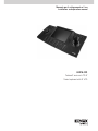
Tastiera 3 assi con LCD 8”
3-axis keyboard with 8” LCD

2
NORME GENERALI DI SICUREZZA
Sicurezza delle persone
Leggere e seguire le istruzioni
Tutte le istruzioni per la sicurezza e per l’operatività devono essere lette e seguite prima che il prodotto sia messo in funzione.
Precauzioni particolari
Rispettare tassativamente l’ordine delle istruzioni di installazione e collegamento descritte nel manuale. Vericare le indicazioni
riportate sulla targa di identicazione: esse devono corrispondere alla vostra rete elettrica di alimentazione ed al consumo
elettrico. Conservate le istruzioni per una consulta futura.
Sicurezza del prodotto
Non posizionare in prossimità di liquidi oppure in un ambiente ad umidità eccessiva. Non lasciare penetrare del liquido o corpi
estranei all’interno dell’apparecchiatura. Non ostruire le griglie di aerazione.
Non sottoporre all’esposizione dei raggi solari oppure in prossimità di fonti di calore.
INFORMAZIONI SULL’AMBIENTE
Note per lo smaltimento del prodotto valide per la Comunità Europea
Questo prodotto è stato progettato e assemblato con materiali e componenti di alta qualità che possono essere
riciclati e riutilizzati. Non smaltire il prodotto come riuto solido urbano ma smaltirlo negli appositi centri di raccolta.
E’ possibile smaltire il prodotto direttamente dal distributore dietro l’acquisto di uno nuovo, equivalente a quello da
smaltire. Abbandonando il prodotto nell’ambiente si potrebbero creare gravi danni all’ambiente stesso. Nel caso il prodotto
contenga delle batterie è necessario rimuoverle prima di procedere allo smaltimento. Queste ultime debbono essere smaltite
separatamente in altri contenitori in quanto contenenti sostanze altamente tossiche.
Il simbolo rappresentato in gura rappresenta il bidone dei riuti urbani ed è tassativamente vietato riporre l’apparecchio
in questi contenitori.L’immissione sul mercato dopo il 1° luglio 2006 di prodotti non conformi al DLgs 151 del 25-07-05 (Direttiva
RoHS RAEE) è amministrativamente sanzionato.
GARANZIA
Questa garanzia ha validità di 2 anni a partire dalla data di acquisto assicurata solo dietro presentazione della fattura o
scontrino rilasciati al cliente dal rivenditore.
L’assistenza gratuita non è prevista per i guasti causati da:
- Uso improprio del prodotto, immagazzinamento inadeguato, cadute o urti, usura, sporcizia, acqua, sabbia, manomissione
da personale non autorizzato del prodotto rispetto a quanto previsto nei manuali d’uso inclusi.
- Riparazioni, modiche o pulizia effettuate da centri assistenza non autorizzati.
- Danni o incidenti le cui cause non possono essere attribuite alla casa madre, comprendenti e non limitati a fulmini, eventi
naturali, alimentazione e ventilazione inadeguata.
Indice
1. Specifiche Tecniche...............................................................................................................................................................1
2. Introduzione......................................................................................................................................................................... 1
3. Funzioni tastiera .................................................................................................................................................................. 2
3.1 Vista frontale ...................................................................................................................................................................... 2
3.2 Aree della tastiera ................................................................................................................................................................ 2
3.3 Vista posteriore .................................................................................................................................................................... 3
3.4 Schema di collegamento ................................................................................................................................................ 4
4. MENU OSD ........................................................................................................................................................................ 5
4.1 Accesso al MENU TASTIERA ............................................................................................................................................. 5
4.2 Keyboard Setup ................................................................................................................................................................... 5
4.3 Dome Setup .................................................................................................................................................................... 5
4.4 Protocol Select .................................................................................................................................................................. 6
4.5 System Setup ..................................................................................................................................................................... 7
4.6 Exit Menu ........................................................................................................................................................................... 7
5. Controllo DVR ....................................................................................................................................................................... 7
5.1 Gestione DVR : comandi disponibili .....................................................................................................................................7
5.2 Gestione DVR da tasti rapidi ...........................................................................................................................................7
6. Controllo Telecamere PTZ...................................................................................................................................................7
6.1 Richiamare un dispositivo PTZ ...........................................................................................................................................8
6.2 Accesso al menù del dispositivo PTZ……………………….................................................……………………............……8
6.3 Gestione PTZ: comandi disponibili ................................................................................................................................. 8
6.4 Gestione PTZ da tasti rapidi............................................................................................................................................. 8
IT

1
VIMAR group
Modello 46916.003
DVR controllabili
46840.D04-46840.D08-46840.D16-46640.W04-46640.W08-46640.W16-46640.W32
46340.F04-46340.F08-46340.F16-46840.F04-46840.F08-46840.F16
46241.F08-46241.F16
Telecamere controllabili
Speed Dome ELVOX ( + speed dome con protocollo Pelco P/D)
Zoom Camera e Telecamere con OSD menù controllabile da RS485 (protocollo Pel-
co P/D)
Protocolli Telecamere e Speed Dome Pelco D, Pelco P, DH-SD, Samsung, Hikvision, LG-Multix
Baud Rate (bps) 2400bps, 4800bps, 9600bps, 19200bps
Indirizzi controllabili 0-255
Range di operatività RS485 1200m su unico bus
Collegamento RS485 una coppia twistata (cavo UTP) A+ , B-
Joystick 3 ASSI , controllo nelle 4 direzioni + zoom integrato rotativo e a pulsante su cloche
Connessioni Bus RS485 (2 morsetti), Input VGA, Input BNC, Plug di alimentazione
Menù OSD Disponibile a schermo
Segnalazione pressione tasti Beep acustico di segnalazione pressione tasti (disattivabile)
Protezione Accesso Chiave Hardware, con blocco completo delle funzioni
Supporto Multi Tastiera Max. 4 tastiere congurabili sullo stesso BUS RS485 (indirizzi da 1 a 64)
Supporto Multi Telecamere e DVR
Max.32 apparati (Speed Dome/Zoom camera/Telecamere con RS485/ DVR) gestibili
sullo stesso BUS RS485
Ingresso VGA 1280x1024, 1024x768, 800x600
Monitor Display TFT 8” con OSD menu (1280x1024, 70Hz)
Temperatura d’utilizzo 0°C / + 50°C
Umidità 10% - 90%
Peso 1830 g
Dimensioni 430×215×146 mm ((compreso joystick)
Alimentazione 12 - 24Vdc (±10%) , max 0.5A, 6.5W
Montaggio Desktop
Dimensioni LCD 8” , (20.3cm diagonale)
Connettore jack/plug Per collegamento ad alimentatore 12Vdc stabilizzati (a corredo)
1 Specifiche tecniche
2 Introduzione
Il dispositivo consente di ottimizzare la gestione remota degli apparati PTZ e DVR della gamma ELVOX su un unico bus RS485.
Il grande display TFT, collegabile direttamente ai DVR, consente di visualizzare e gestire in diretta sia le movimentazioni delle
telecamere motorizzate, sia il menù dei DVR collegati.
Il menù OSD consente la selezione dei canali e dei protocolli necessari al collegamento multi-apparato su connessione BUS
RS485. Il display è regolabile per adattarlo alle condizioni ambientali in cui è posto il prodotto.
I tasti rapidi dedicati, presenti nella sezione tasti DVR e PTZ, consentono di gestire in modo intuitivo i singoli dispositivi.
IT

2
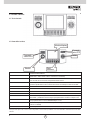
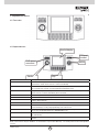
3 Funzioni tastiera
3.1 Vista frontale
3.2 Aree della tastiera
Nome
Descrizione Tasti Funzione
CAM Sceglie l’indirizzo (ID) di qualunque dispositivo da controllare
(Speed Dome / DVR / Zoom Camera / Telecamera con RS485)
MENU Premuto 1 secondo: dà informazioni sui dati di tastiera / visualizza i tasti digitati. Premuto
per 6 secondi: entra nel menù di congurazione della tastiera
SHI
Durante la gestione DVR, ad ogni pressione attiva la modalità di controllo del PTZ (per
dispositivi: Speed Dome/ Zoom Camera/ Telecamere con RS485) ma attraverso il DVR.
0-9
Tastiera numerica: “ 0, 1, 2, 3, 4, 5, 6, 7, 8, 9 “
ESC / <
Esce dalla funzione o torna al livello di menù precedente
ENTER / >
Conferma / Entra nel sottomenù
PREV / NEXT
Aumenta/diminuisce il valore presente sul display.
LCD Accede al menù per le regolazioni del monitor interno alla tastiera (Luce, contrasto, po-
sizione OSD,…) Utilizzare i tasti freccia per la programmazione. Premere LCD per uscire.
IN / MONITOR Accede al menù di scelta dell’ingresso video connesso alla tastiera. Utilizzare i tasti freccia
per la programmazione. Premere IN/MONITOR per uscire.
PRE/SET/PAT/ TOUR/SCAN Attivano la corrispondente funzione sul dispositivo PTZ (Speed Dome/ Zoom Camera/ Te-
lecamere con RS485)
SHUTTLE / JOG
Utilizzabile per scorrere le voci dei vari menù interni ad alcune versioni di tastiera
Nota: per alcuni protocolli, e alcune versioni di prodotto, alcune funzioni potrebbero non essere attivabili o taluni tasti funzionare diver-
samente.
IT
Monitor/display
Comandi
veloci DVR
Shuttle
Tasti
funzione
Jostick
Comandi
veloci PTZ

3
VIMAR group
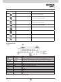
3 Funzioni tastiera
3.1 Vista frontale
Posizione Operazione Funzione
SU Nel modo PTZ : controlla i movimenti di pan/tilt in su
Nei menù: spostamento cursore in su
GIU’ Nel modo PTZ: controlla i movimenti di pan/tilt in giù
Nei menù: spostamento cursore in giù
SINISTRA Nel modo PTZ: controlla i movimenti di pan/tilt a sinistra
Nei menù: spostamento cursore a sinistra
DESTRA Nel modo PTZ: controlla i movimenti di pan/tilt a destra
Nei menù: spostamento cursore a destra
ROTAZIONE in senso antiorario Nel modo PTZ : Zoom -/OUT
ROTAZIONE in senso orario Nel modo PTZ : Zoom +/IN
PRESSIONE PULSANTE DX Nel modo PTZ: Zoom IN
PRESSIONE PULSANTE SX Nel modo PTZ: Zoom OUT
Nota: per alcune versioni (e protocolli) alcune funzioni potrebbero non essere abilitati.
Nome Funzione
Descrizione
Power input Ingresso alimentazione
Plug di Alimentazione 12Vdc. Collegare a una fonte stabilizzata.
RS485 Controllo PTZ
Collegare la tastiera al bus (telecamere con RS485/speed dome/zoom camera/
DVR). Seguire la polarità indicata sul connettore (RS485+A , RS485- B)
Video input Ingresso BNC
Ingresso video analogico. Collegare l’uscita video proveniente da una telecamera,
speed dome o DVR
VGA Ingresso VGA
Collegare l’uscita video VGA proveniente da un DVR
4CH
Non attivo
RS485 match 1-2 on-off
Resistenze terminali integrate per chiusura BUS485
RS232 RS232
Connettore di programmazione (test di fabbrica)
NC-NC Non utilizzati
VISCA Non utilizzato
RJ45 Non utilizzato
USB Non utilizzato
LOCK Chiave di sicurezza, per blocco tastiera
POWER Interruttore di alimentazione
3.3 Aree della tastiera
Figura 2
IT
Funzioni di controllo da Joystick
N.B. Posizionare la chiave di sicurezza per blocco tastiera sul puntino rosso.
Alimentazione
Serratura
Interfaccia
dispositivo di
commutazione
resistenza terminale
on / off
Ingresso video
Ingresso
alimentazione

4
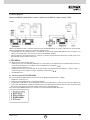
3.4 Schema di collegamento
Controllo su RS485 (speed dome / telecamere con menù su RS485 / zoom camera / DVR)
Figura 2
4 MENU OSD
La tastiera dispone di diversi menù interni.
• Menù INGRESSI: premendo il tasto IN/MONITOR vi è la possibilità di settare l’ingresso da visualizzare sul monitor
interno alla tastiera. Lo scorrimento delle voci del menù può avvenire con i tasti freccia Su/Giù (
>
).
Freccia Dx per confermare ( > ).
• Menù MONITOR: premendo il tasto LCD è possibile selezionare i parametri del monitor interno (luminosità, con-
trasto, colore, …). Lo scorrimento delle voci del menù può avvenire con i tasti freccia Su/Giù (
>
).
• Menù TASTIERA.
4.1 Accesso al MENU TASTIERA
Premendo brevemente il tasto MENU si ottiene la visualizzazione di alcuni parametri programmati, in particolare:
• “BaudRate” in uso
• “Protocol” del prodotto da utilizzare attraverso la tastiera
• “Keyboard ID”: ID della tastiera. Nello stesso impianto sono collegabili max.4 tastiere,ognuna con un diverso ID.
• “Camera ID”. Numero identicativo del prodotto da controllare (telecamera o DVR). Solo questo valore è modica-
bile direttamente nella videata (premere il numero desiderato e poi premere il tasto CAM)
Premendo continuamente per 5 secondi il tasto MENU si accede invece al menù OSD programmabile.
>
Bilanciare la linea RS485 con una resistenza terminale da 120 ohm posta tra A+ e B- della telecamera/speed più lon-
tana. Il bilanciamento va effettuato anche sull’altro lato del bus:
• se l’ultimo elemento connesso al bus è una tastiera, utilizzare gli switch previsti (“RS485 match” in gura2): porre
switch 1 su ON, switch 2 su ON (solo sull’ultima tastiera del bus)
• se l’ultimo elemento connesso al bus e’ un DVR, inserire una resistenza da 120 ohm posta tra i morsetti A+ e B- (in
questo caso , gli switch della tastiera saranno posizionati su OFF)
IT
Tastiera
Tastiera
(Impostazioni tastiera)
(Impostazioni tel. Dome)
(Selezione protocollo)
(Impostazione sistema)
(Uscita menù)

5
VIMAR group
Posizionare il cursore sul campo prescelto usando il Joystick (o le frecce) e premere ENTER.
In alternativa, le azioni svolte dal tasto ENTER possono essere realizzate anche premendo il tasto > oppure muovendo
il joystick verso destra.
Per uscire dalla voce selezionata o tornare al menù precedente: premere il tasto < oppure muovere il joystick verso
sinistra.
4.2 Keyboard Setup
Dal MENU TASTIERA selezionare il parametro e entrare premendo ENTER (o tasto >).
1. SET KB ID 1-64: 01
2. SET BAUDRATE: 2400BPS
3. Joy calibrate
4. About Keyboard
1. SET KB ID: inserire l’indirizzo ID della keyboard spostando il joystick a Dx (o premendo il tasto >, o ENTER) .
Digitare il valore numerico da 1 a 64 utilizzando la tastiera numerica. ENTER per confermare.
Nota: non è necessario che il valore ID della tastiera sia differente da quello degli altri apparati (speed/telecamere/
DVR).
2. SET BAUDRATE: selezionare il valore del Baud Rate di sistema (2400-4800-9600-19200) comune a tutti i disposi-
tivi connessi (speed, DVR, tastiere, …). Per la connessione con DVR utilizzare il valore “9600”.
Il valore del Baud Rate di comunicazione deve tenere conto della distanza che intercorre tra la tastiera e l’ultimo
dispositivo da controllare.
Nota: se le condizioni installative lo consentono, può essere comodo impostare un unico valore su tutti i prodotti
connessi al bus RS485, evitando così di doverlo reimpostare ad ogni connessione.
Premere ENTER (o joystick a Dx, o >) per confermare. Premere PREV (o tasto <, o joystick a Sx) per tornare al
menù. Sul display verrà mostrata la scritta “SUCCESS” a indicare che l’operazione è riuscita.
3. Joy calibrate: utility per la calibrazione del Joystick. L’azzeramento avviene quando il joystick è in posizione cen-
trale premendo il tasto ENTER.
4. About Keyboard: premendo ENTER vengono visualizzati i parametri di controllo impostati per la tastiera.
4.3 Dome Setup
Dal MENU TASTIERA selezionare il parametro e entrare premendo ENTER (o tasto >).
>
Selezionare e accedere ai sottomenù premendo ENTER e spostandosi con i tasti freccia o joystick. Premere PREV
per uscire dal sottomenù.
4.3.1 Set dome preset
SAVE PRESET: premere ENTER, con il joystick muovere la speed sino al punto da memorizzare (ed eventualmente
effettuare lo zoom); selezionare il numero di preset da assegnare. Premere ENTER e il preset verrà memorizzato nella
speed dome.
SHOW PRESET: premere ENTER (o tasto > o joystick Dx), selezionare il Preset che si vuole visualizzare ed ENTER
per spostare la speed in quel punto.
CLEAR PRESET: premere ENTER (o tasto > o joystick Dx), selezionare il Preset che si vuole cancellare. PREMERE
ENTER per
cancellare il preset dalla memorizzazione della speed.
Nota: con alcuni modelli di speed dome la funzione e’ gestita solo dal menù della stessa.
4.3.2 Set dome scan
SET LEFT LIMIT: premere ENTER, con il joystick muovere la speed (ed eventualmente effettuare lo zoom) sino al punto
da memorizzare come limite sinistro del brandeggio (SCAN). Premere ENTER.
SET RIGHT LIMIT: premere ENTER, con il joystick muovere la speed (ed eventualmente effettuare lo zoom) sino al
punto da memorizzare come limite destro del brandeggio (SCAN). Premere ENTER.
IT
(Impostazione telecamera Dome preregistrata)
(Scansione telecamere Dome)
(Impostazione modello telecamere Dome)
(Impostazione tour telecamere)

6
RUN SCAN : premere ENTER per avviare lo SCAN tra i due punti memorizzati. Lo SCAN verrà ripetuto sino a nuovo comando.
Nota: normalmente lo SCAN verrà memorizzato nella speed dome come SCAN1.
Con alcuni modelli di speed dome la funzione e’ gestita solo dal menù della stessa .
4.3.3 Set dome pattern
PATTERN NUM: digitare in tastiera il numero di pattern desiderato. Premere ENTER. Si attivano i due sottomenù
successivi. SET PATTERN: premere ENTER, con il joystick muovere la speed (ed eventualmente effettuare lo zoom)
sino al punto scelto come inizio del percorso da memorizzare; premere 1 per avviare la registrazione del percorso.
Creare con il joystick e lo zoom il percorso desiderato.
Nota: ogni movimento PTZ e ogni pausa verranno memorizzati nella speed dome esattamente come effettuati; verran-
no ripetuti con la stessa velocità utilizzata durante la registrazione…
Premere 0 per terminare la registrazione del Pattern.
RUN PATTERN: premere ENTER e il Pattern selezionato verrà avviato e ripetuto sino a nuovo comando.
Nota: con alcuni modelli di speed dome la funzione e’ gestita solo dal menù della stessa .
4.3.4 Set dome tour
TOUR NUM: digitare in tastiera il numero di Tour/Cruise/Sequence desiderato. Premere ENTER.
Si attivano i due sottomenù successivi.
INSERT PRESET: premere ENTER (o tasto > o joystick Dx). Verranno richiesti i punti pre-memorizzati da inserire nel Tour
(PRESET NUM), il tempo di permanenza su quel Preset durante la sequenza (DWELL), la velocità di spostamento (SPEED).
RUN TOUR: premere ENTER e il TOUR selezionato verrà avviato e ripetuto sino a nuovo comando.
Nota: con alcuni modelli di speed dome la funzione e’ gestita solo dal menù della stessa .
4.4 Protocol Select
Dal MENU TASTIERA selezionare il parametro e entrare premendo ENTER (o tasto >).
1. MATRIX-DVR
2. DOME
Selezionare il protocollo di comunicazione che si vuole utilizzare.
MATRIX-DVR : Premendo ENTER vengono mostrati in elenco tutti i protocolli compatibili per la gestione menu dei DVR
(selezionare STADVR per i DVR ELVOX). Premere ENTER per confermare.
DOME: premendo ENTER vengono mostrati tutti i protocolli compatibili per la gestione di movimenti e dei MENU
di Speed Dome, zoom camera e telecamere con menù controllabile da RS485. Selezionare il protocollo identico a
quanto presente su questi apparati confermando con il tasto ENTER.
L’indicazione “SUCCESS” a display conferma l’avvenuta modica.
L’operazione andrà ripetuta ogni volta che ci si connette ad un prodotto con protocollo diverso.
4.5 System Setup
1.
BUZZER: selezionare, premere tasto > per attivare/disattivare il Buzzer di conferma pressione tasti. Premere ENTER per
confermare.
2. AUTO SCAN: non attivo
3. USB MODE: non attivo
4. INIT. SYSTEM: selezionare per riportare la tastiera alla programmazione di fabbrica di tutti i parametri. Premere il
tasto PREV per tornare al menù precedente.
4.6 Exit Menù
Selezionare la voce EXIT MENU e premere ENTER per uscire dal menù
5 Controllo DVR
Per accedere al menù OSD del DVR premere brevemente il tasto MENU.
Sarà possibile effettuare le operazioni di controllo del DVR se a video risultano presenti:
• In “Protocol”, il protocollo programmato per la gestione del DVR. Selezionare TVTDVR per i DVR ELVOX.
• In “Baudrate” , la velocità di trasmissione prevista per la gestione del DVR. Per la connessione con DVR ELVOX
utilizzare il valore “9600”.
• In “Camera ID”, il valore ID assegnato nel DVR (nei DVR ELVOX l’ID e’ generalmente rintracciabile in
menù/setup/generale). Per selezionare l’ID di un altro DVR, inserire l’indirizzo del DVR da controllare (ID validi:
0-15) digitandolo sulla tastiera numerica (o utilizzare i tasti PREV/NEXT), poi premere il tasto CAM.
A questo punto sono disponibili i comandi del DVR.
IT

7
VIMAR group
Nota: ogni DVR potrebbe avere comandi differenti o aggiuntivi rispetto a quanto illustrato.
5.1 Gestione DVR : comandi disponibili
Utilizzando DVR ELVOX e’ attualmente disponibile l’accesso alle seguenti funzioni del DVR.
Premere il tasto ESC per accedere alla barra del menù del ns. DVR.
Muovere il Joystick nelle 4 direzioni per muovere il cursore all’interno del menù OSD del DVR. Premere ENTER per
entrare in ogni campo editabile. Premere ESC per uscire dal campo.
Tasto SHI: con questo tasto è possibile accedere alla modalità di comando PTZ attraverso il DVR. Tasti numerici:
richiamano il canale video del DVR a schermo pieno.
Tasto TOUR: attiva il menù volume audio del DVR
Tasto < (freccia Sx): attiva il menù INFORMAZIONI del DVR
Tasto
>
(freccia Su): attiva il menù per lo spegnimento del DVR
Tasto
>
(freccia Giù): attiva il menù per il BACKUP registrazioni da DVR
Nota: per alcuni modelli e protocolli alcune funzioni potrebbero non essere abilitate.
5.2 Gestione DVR da tasti rapidi
In tastiera e’ presente un gruppo di TASTI RAPIDI di comando (posti in alto sul lato sinistro della tastiera). Utilizzando
DVR ELVOX permettono l’accesso veloce alle seguenti funzioni del DVR.
Tasto
: attiva il menù di Ricerca registrazioni sul DVR
Tasto
: attiva sul DVR la visualizzazione di un canale a schermo pieno.
Premere nuovamente per passare alla vista del canale successivo.
Tasto
: attiva sul DVR la visualizzazione di 4 canali in contemporanea.
Premere nuovamente per passare alla vista dei 4 canali successivi.
Tasto
: attiva sul DVR la visualizzazione di 9 canali in contemporanea.
Tasto
: attiva sul DVR la visualizzazione di 16 canali in contemporanea.
Tasto
: attiva sul DVR la visualizzazione di 9 canali in contemporanea.
Tasto
: attiva sul DVR la Registrazione manuale. Premere nuovamente per fermare la reg. manuale.
Tasto
: attiva sul DVR il Playback dell’ultima registrazione effettuata.
Premere nuovamente per fermare momentaneamente lo scorrimento (Pausa).
Per visualizzare a tutto schermo i canali delle singole telecamere, utilizzare il tastierino numerico dall’ 1 al 9.
Per i canali dal 10 in poi, seguire la seguente procedure:
= 10
0
1
0
= 64
4
6
0
Nota: per alcuni modelli e protocolli alcune funzioni potrebbero non essere abilitate.
6 Controllo Telecamere PTZ
E’ possibile collegarsi a vari modelli di dispositivi PTZ:
• Telecamere dotate di bus RS485 (per gestirne il solo menù OSD)
• Zoom Camera dotate di bus RS485 (per gestirne lo zoom e il menù OSD)
• Speed Dome dotate di bus RS485 (per gestirne i movimenti, lo zoom e il menù OSD)
I dati di ogni telecamera devono essere precedentemente inseriti nella programmazione della tastiera come illustrato
al paragrafo “Keyboard Setup” (baud rate) e “Protocol Select / Dome” (protocollo)
Nota: si consiglia di utilizzare protocollo e baud rate uguali per tutti i dispositivi connessi, differenziandoli solo per
indirizzo.
6.1 Richiamare un dispositivo PTZ
Premendo brevemente il tasto MENU è possibile vericare le impostazioni attive.
La connessione al dispositivo sarà possibile se
• In “Protocol”, il protocollo programmato e’ lo stesso settato nel dispositivo da controllare.
Nota: se era in corso la gestione di un DVR, sarà necessario prima variare il protocollo nella programmazione della
tastiera.
IT

8
• In “Baudrate” , la velocità di trasmissione è identica a quanto programmato nel dispositivo da controllare.
• In “Camera ID”, il valore ID e’ lo stesso di quello assegnato al dispositivo da controllare. Per selezionare l’ID di un
altro dispositivo premere il tasto CAM, inserire l’indirizzo da controllare (ID validi: 0-255) digitandolo sulla tastiera
numerica (o utilizzare i tasti PREV/NEXT).
A questo punto sono disponibili i comandi del dispositivo PTZ.
Nota: ogni dispositivo potrebbe avere comandi differenti o non attivabili rispetto a quanto illustrato.
Seguire le istruzioni a corredo del dispositivo.
6.2 Accesso al menù del dispositivo PTZ
Agire ora sui comandi PTZ tramite tastiera o da Joystick o dai comandi veloci.
Per entrare nel menu dei dispositivi PTZ utilizzare il comando previsto dal costruttore.
Per le Speed Dome/Telecamere/ZoomCamera richiamare il preset 95 (digitando 95 e premendo PRE).
Il menù OSD del dispositivo PTZ verrà mostrato a schermo.
Muoversi con il joystick tra le varie voci del menù OSD. Per entrare nella funzione selezionata: muovere il joystick a Dx,
oppure premere IRIS OPEN+ oppure ENTER (il comando può cambiare a seconda del modello/protocollo di prodotto
PTZ). Per uscire
dalla funzione: muovere il joystick a Sx, premere IRIS CLOSE- o ESC, selezionare EXIT/BACK (se presenti nel menù).
6.3 Gestione PTZ: comandi disponibili
Per i movimenti Pan & Tilt utilizzare il joystick.
Per lo zoom e’ possibile utilizzare: il joystick ruotandolo in entrambi i sensi, o i tasti presenti sul joystick stesso, o i
COMANDI VELOCI (TELE / WIDE)
Tasto PRE: per richiamare un Preset programmato. Digitare il numero del PRESET da lanciare seguito dal tasto PRE.
La speed dome / zoom camera si posizionerà su quel preset.
Tasto SET: per memorizzare un Preset. Posizionare la speed dome/zoom camera sul punto da impostare.
Digitare il numero del PRESET da creare seguito dal tasto SET. Premere ENTER (o PRE).
Tasto SCAN: per avviare uno SCAN preprogrammato. Digitare il numero dello SCAN da lanciare seguito dal tasto
SCAN.
Premere ENTER.
Tasto TOUR: per avviare un TOUR preprogrammato. Digitare il numero del TOUR da lanciare seguito dal tasto TOUR.
Eventualmente premere ENTER.
Tasto PAT: per avviare un PATTERN preprogrammato. Digitare il numero del PATTERN da lanciare seguito dal tasto
PATTERN.
Eventualmente premere ENTER.
Nota: ogni dispositivo gestito potrebbe avere comandi differenti o non attivabili rispetto a quanto illustrato.
Seguire le istruzioni a corredo del dispositivo.
6.4 Gestione PTZ da tasti rapidi
In tastiera e’ presente un gruppo di TASTI RAPIDI di comando (posti in alto sul lato destro della tastiera).
Tasto OPEN: comando per aprire l’IRIS (IRIS+) manualmente. Utilizzato anche per confermare le opzioni nel
menù OSD di alcune speed dome/telecamere e l’ingresso nei sottomenù.
Tasto CLOSE: comando per chiudere l’IRIS (IRIS-) manualmente. Utilizzato anche per uscire dalle opzioni del
menù OSD di alcune speed dome/telecamere.
Tasti NEAR/FAR: comandi per la messa a fuoco manuale.
Tasti TELE/WIDE: comandi per lo Zoom manuale.
Tasti LIGHT/WIPER: comandi per l’attivazione/disattivazione del tergicristallo e per l’accensione/spegnimento dei
LED nelle
Speed Dome.
Tasto GO TO : accede al menù di lancio dei preset. Digitare il numero di preset da lanciare e premere ENTER.
Premere ancora GOTO per uscire dalla funzione. Premendo invece PREV si accede al menù
SET DOME PRESET (ved.)
Nota: ogni dispositivo potrebbe avere comandi differenti o non attivabili rispetto a quanto illustrato.
Seguire le istruzioni a corredo del dispositivo.
IT

9
VIMAR group
GENERAL SAFETY PRECAUTIONS
Personal safety
Read and comply with all instructions
Read and comply with all the safety and operating instructions before operating the product.
Special precautions
Strictly comply with the order of the installation and wiring instructions given in the manual. Check the information
on the data plate: the data must correspond to your power connection and the electrical consumption. Keep these
instructions for future consultation.
Product safety
Do not place near liquids or in an excessively humid environment. Do not allow liquid or other materials to penetrate
inside the appliance. Do not obstruct the air vents.
Keep away from direct sunlight or heat sources.
ENVIRONMENTAL INFORMATION
Product disposal provisions in force in the European Union
This product was designed and assembled using high quality materials and components which can be recycled
and reused. Do not dispose of the product as municipal waste; dispose of only at specic disposal sites. You
can also dispose of this product when purchasing a new equivalent one from your dealer. Littering can cause serious
damage to the environment. If the product has batteries, remove them before disposal. Batteries must be disposed of
separately in special containers, as they contain highly toxic substances.
The symbol shown in the gure is a municipal waste bin, it is strictly forbidden to dispose of the appliance in these
containers. Since 1 July 2006, the market release of products that do not comply with Italian Legislative Decree (D.Lgs)
151 dated 25-07-05 (RoHS/WEEE Directive) is subject to administrative sanctions.
WARRANTY
This warranty is valid for 2 years from the date of purchase, as proven by the invoice or receipt is-
sued by the dealer.
The warranty is not valid for damage caused by:
- Improper use, inappropriate storage, knocks, dropping, wear, dirt, water, sand, tampering with the product by un-
authorised staff and any handling that is not described in this user manual, including:
- Repairs, modications or cleaning performed by unauthorised servicing centres.
- Damage or accidents not caused by the manufacturer, including but not limited to lightning, natural calamities, inap-
propriate power sources or ventilation.
Contents
1. Technical Specifications..........................................................................................................................................9
2. Introduction.......................................................................................................................................................... 10
3. Keyboard functions............................................................................................................................................... 11
3.1 Front view .............................................................................................................................................................11
3.2 Keyboard areas ...................................................................................................................................................... 11
3.3 Rear view ............................................................................................................................................................ 13
3.4 Wiring diagram ........................................................................................................................................................ 13
4. OSD MENU ........................................................................................................................................................ 14
4.1 Accessing the KEYBOARD MENU ......................................................................................................................... 14
4.2 Keyboard Setup ..................................................................................................................................................... 14
4.3 Dome Setup .......................................................................................................................................................... 14
4.4 Protocol Select ................................................................................................................................................. 15
4.5 System Setup ..................................................................................................................................................... 16
4.6 Exit Menu ............................................................................................................................................................. 16
5. DVR control ........................................................................................................................................................ 16
5.1 DVR management: available commands ..................................................................................................................16
5.2 DVR management via shortcut buttons ....................................................................................................................16
6. PTZ camera control ...........................................................................................................................................16
6.1 Recalling a PTZ device .......................................................................................................................................17
6.2 Accessing the PTZ device menu ……………………………………………………………......…………............……17
6.3 PTZ management: available commands ................................................................................................................ 17
6.4 PTZ management via shortcut buttons..................................................................................................................17
EN

10
Model 46916.003
DVR control
46840.D04-46840.D08-46840.D16-46640.W04-46640.W08-46640.W16-46640.
W32
46340.F04-46340.F08-46340.F16-46840.F04-46840.F08-46840.F16
46241.F08-46241.F16
Speed dome control ELVOX Speed Dome (+ speed dome with Pelco P/D protocol)
Fixed camera control
Zoom Camera and cameras with menu OSD controlled via RS485 (Pelco P/D pro-
tocol)
Camera and Speed Dome
protocols Pelco D, Pelco P, DH-SD, Samsung, Hikvision, LG-Multix
Baud rate (bps) 2400 bps, 4800 bps, 9600 bps, 19200 bps
Addresses that can be con-
trolled 0-255
RS485 operating range 1200 m on single bus
RS485 wiring One twisted pair (UTP cable) A+, B-
Joystick 3 AXES, control in 4 directions + integrated rotary zoom and via joystick button
Connections RS485 Bus (2 terminals), VGA input, BNC input, power supply plug
OSD menu Available on screen
Button press indication Audible beep indicating button press (can be deactivated)
Access protection Hardware key with complete function lock
Multi-keyboard support
Max. 4 keyboards can be congured on the same RS485 BUS (addresses from 1
to 64)
Multi camera and DVR sup-
port
Max. 32 devices (Speed Dome/Zoom Camera Cameras with RS485/DVR) can be
managed on the same RS485 BUS
VGA input 1280x1024, 1024x768, 800x600
Monitor 8” TFT display with OSD menu (1280x1024, 70 Hz)
Operating temperature 0°C / + 50°C
Humidity 10% - 90%
Weight 1830 g
Dimensions 430×215×146 mm (including joystick)
Power supply 12 - 24 Vdc (±10%), max. 0.5 A, 6.5 W
Mounting Desktop
LCD dimensions 8” (20.3 cm diagonal)
Jack/plug connector For connection to 12 Vdc regulated power supplies (supplied)
1 Technical specifications
2 Introduction
The device helps to optimise remote management of ELVOX PTZ and DVR instruments on a single RS485 bus. The
large TFT display, which can be connected directly to the DVRs, allows direct viewing and management of both mo-
torised camera movement and the menu for connected DVRs.
The OSD allows selection of the channels and protocols required for multi-device connection on RS485 BUS. The
display can be adjusted to suit the conditions of the environment in which the product is located.
The special shortcut buttons in the DVR and PTZ button section can be used for intuitive management of the individual
devices.
EN

11
VIMAR group
3.2 Keyboard areas
Name
Description of Function buttons
CAM Select the address (ID) of whichever device you wish to control
(Speed Dome / DVR / Zoom Camera / Camera with RS485)
MENU Pressed for 1 second: provide information regarding keyboard data / display pressed but-
tons. Pressed for 6 seconds: enter the keyboard conguration menu
SHI
During DVR management, each press activates PTZ control mode (for devices: Speed Dome
/ Zoom Camera / Cameras with RS485) but via the DVR
0-9
Numerical keyboard: "0, 1, 2, 3, 4, 5, 6, 7, 8, 9"
ESC / <
Exit the function or return to the previous menu level
ENTER / >
Conrm / Enter submenu
PREV / NEXT
Increase/decrease the value shown on the display
LCD Access the built-in keyboard monitor adjustment menu (light, contrast, OSD position, ...).
Use the arrow keys to carry out programming. Press LCD to exit
IN / MONITOR Access the menu for selecting the video input connected to the keyboard. Use the arrow
keys to carry out programming. Press IN/MONITOR to exit
PRE/SET/PAT/ TOUR/SCAN Activate the corresponding function on the PTZ device (Speed Dome/ Zoom Camera / Cam-
eras with RS485)
SHUTTLE / JOG Can be used to scroll through the options on the various menus built into certain keyboard
versions
Note: some functions may be disabled - or some buttons may function differently - for certain protocols and certain product
versions.
3 Keyboard functions
3.1 Front view
EN
Monitor/display
DVR speed
command
Shuttle
Function
keys
Jostick
PTZ Speed
command

12
Position Procedure Function
UP In PTZ mode: check upward pan/tilt movements
In menus: move cursor upwards
DOWN In PTZ mode: check downward pan/tilt movements
In menus: move cursor downwards
LEFT In PTZ mode: check pan/tilt movements to the left
In menus: move cursor to the left
RIGHT In PTZ mode: check pan/tilt movements to the right
In menus: move cursor to the right
Anticlockwise ROTATION In PTZ mode: Zoom -/OUT
Clockwise ROTATION In PTZ mode: Zoom +/IN
RH BUTTON PRESS In PTZ mode: Zoom IN
LH BUTTON PRESS In PTZ mode: Zoom OUT
Note: some functions may be disabled for certain versions (and protocols).
Name Function Description
Power input Power supply input 12 Vdc power supply plug. Connect to a regulated source
RS485 PTZ control Connect the keyboard to the bus (cameras with RS485/speed dome/zoom camera/
DVR). Observe the polarity indicated on the connector (RS485+A, RS485- B)
Video input BNC input Analogue video input. Connect the video output from a camera, speed dome or DVR
VGA VGA input Connect the VGA video output from a DVR
4CH Inactive
RS485 match 1-2 on-off Built-in terminal resistors for BUS485 closure
RS232 RS232 Programming connector (factory test)
POWER Power switch
VISCA Not used
RJ45 Not used
USB Not used
LOCK Safety key to lock keyboard
POWER Power switch
3.3 Keyboard areas
Figure 2
N.B. Place the security key for the lock on the red dot.
EN
Joystick control functions

13
VIMAR group
3.4 Wiring diagram
Control on RS485 (speed dome / cameras with menu on RS485 / zoom camera / DVR)
Figure 2
Balance the RS485 line with a 120 Ohm terminal resistor positioned between A+ and B- of the furthest camera/speed.
Balancing should also be carried out on the other side of the bus:
• if the last element connected to the bus is a keyboard, use the switches provided (“RS485 match” in gure 2): set
switch 1 to ON and switch 2 to ON (only for the last keyboard on the bus)
• if the last element connected to the bus is a DVR, t a 120 Ohm resistor between terminals A+ and B- (in this case,
the keyboard switches will be set to OFF)
4 OSD MENU
The keyboard has various built-in menus.
• INPUT menu: press the IN/MONITOR button to set the input to be displayed on the monitor built into the key-
board. Scroll through the menu options using the Up/Down arrow buttons (
>
).
Conrm using the RH arrow ( > ).
• MONITOR menu: press the LCD button to select the built-in monitor parameters (brightness, contrast, colour, …).
Scroll through the menu options using the Up/Down arrow buttons (
>
).
• KEYBOARD menu.
4.1 Accessing the KEYBOARD MENU
Press and release the MENU button to view some of the programmed parameters, notably:
• “BaudRate” currently in use
• “Protocol” for the product to be used via the keyboard
• “Keyboard ID”: keyboard ID. Up to 4 keyboards can be connected within the same system, each with a different ID
• “Camera ID”: identication number of the product to be controlled (camera or DVR). Only this value can be changed
directly on screen (press the desired number and then press the CAM button)
Press and hold the MENU button for 5 seconds to access the programmable OSD menu.
>
EN

14
Use the joystick (or the arrows) to position the cursor on the selected eld and press ENTER.
Alternatively, the actions executed by the ENTER button can also be performed by pressing the > button, or by moving
the joystick to the right.
To exit the selected option or return to the previous menu: press the < button or move the joystick to the left.
4.2 Keyboard Setup
From the KEYBOARD MENU, select the parameter and conrm by pressing ENTER (or the > button).
1. SET KB ID 1-64: 01
2. SET BAUDRATE: 2400 BPS
3. Joy calibrate
4. About Keyboard
1. SET KB ID: enter the keyboard ID by moving the joystick to the right (or by pressing the > button, or ENTER).
Enter the numerical value from 1 to 64 using the numerical keyboard. ENTER to conrm.
Note: the keyboard ID value does not have to differ from the value of other equipment (speed/cameras/DVR).
2. SET BAUDRATE: select the system Baud Rate value (2400-4800-9600-19200) shared by all connected devices
(speed, DVR, keyboards, …). For connection with DVRs, use the value “9600”.
The communication Baud Rate value must take account of the distance between the keyboard and the last device
to be controlled.
Note: if installation conditions allow, it may be useful to set a single value for all products connected to the RS485
bus, meaning you will avoid having to reset it every time connection takes place.
Press ENTER (or joystick to the right, or >) to conrm. Press PREV (or < button, or joystick to the left) to return to the
menu. The text “SUCCESS” will appear on the display to indicate that the procedure was completed successfully.
3. Joy calibrate: joystick calibration utility. Reset takes place by pressing the ENTER button when the joystick is in its
central position.
4. About Keyboard: press ENTER to display the control parameters set for the keyboard.
4.3 Dome Setup
From the KEYBOARD MENU, select the parameter and conrm by pressing ENTER (or the > button).
>
Select and access the submenus by pressing ENTER and using the arrow buttons or joystick to navigate. Press PREV
to exit the submenu.
4.3.1 Set dome preset
SAVE PRESET: press ENTER, use the joystick to move the speed to the point you wish to memorise (and zoom as
required); select the preset number to assign. Press ENTER; the preset value will be memorised in the speed dome.
SHOW PRESET: press ENTER (or > button, or move joystick right), select the Preset you want to view and ENTER to
move the speed to that point.
CLEAR PRESET: press ENTER (or > button, or move joystick right), select the Preset you want to delete. PRESS EN-
TER to delete the preset value from the speed memory.
Note: in some speed dome models, the function is only managed via that menu.
4.3.2 Set dome scan
SET LEFT LIMIT: press ENTER, use the joystick to move the speed (and zoom as required) to the point you wish to
memorise as the left-hand pan (SCAN) limit. Press ENTER.
SET RIGHT LIMIT: press ENTER, use the joystick to move the speed (and zoom as required) to the point you wish to
memorise as the right-hand pan (SCAN) limit. Press ENTER.
RUN SCAN: press ENTER to start the SCAN between the two memorised points. The SCAN will be repeated until a
new command is made.
Note: normally the SCAN will be memorised in the speed dome as SCAN1.
In some speed dome models, the function is only managed via that menu.
EN

15
VIMAR group
4.3.3 Set dome pattern
PATTERN NUM: use the keyboard to enter the desired pattern number. Press ENTER. The two subsequent submenus
are activated. SET PATTERN: press ENTER, use the joystick to move the speed (and zoom as required) to the point
selected as the start of the path to be memorised; press 1 to start recording the path.
Create the desired path using the joystick and the zoom.
Note: every PTZ movement and every pause will be memorised in the speed dome exactly as they are carried out; they
will be reproduced at the same speed as used during recording…
Press 0 to end Pattern recording.
RUN PATTERN: press ENTER to start replaying the selected Pattern until a new command is made.
Note: in some speed dome models, the function is only managed via that menu.
4.3.4 Set dome tour
TOUR NUM: use the keyboard to enter the desired Tour/Cruise/Sequence number. Press ENTER.
The two subsequent submenus are activated.
INSERT PRESET: press ENTER (or > button, or move joystick right). The previously memorised points must be entered in the Tour
(PRESET NUM), along with the time spent on that Preset during the sequence (DWELL), and the movement speed (SPEED
).
RUN TOUR: press ENTER to start replaying the selected Tour until a new command is made.
Note: in some speed dome models, the function is only managed via that menu.
4.4 Protocol Select
From the KEYBOARD MENU, select the parameter and conrm by pressing ENTER (or the > button).
1. MATRIX-DVR
2. DOME
Select the communication protocol you wish to use.
MATRIX-DVR: Press ENTER to display a list of all compatible protocols for DVR menu management (select STADVR
for ELVOX DVRs). Press ENTER to conrm.
DOME: press ENTER to display a list of all compatible protocols used to manage movement and the MENUs for Speed
Dome, zoom camera and cameras with menus that can be controlled via RS485. Select the protocol identical to the
one present on these devices, conrming with the ENTER button.
"SUCCESS" on the display conrms that the change has been made successfully.
The procedure must be repeated every time a connection to a product with different protocol takes place.
4.5 System Setup
1.
BUZZER: select, press the > button to activate/deactivate the button press conrmation buzzer. Press ENTER to conrm.
2. AUTO SCAN: inactive
3. USB MODE: inactive
4. INIT. SYSTEM: select to restore all keyboard parameters to their factory default settings. Press the PREV button
to return to the previous menu.
4.6 Exit Menu
Select EXIT MENU and press ENTER to exit the menu.
5 DVR control
To access the OSD menu for the DVR, press and release the MENU button.
DVR control procedures can be carried out if the following appear on screen:
• In “Protocol”, the protocol programmed for DVR management. Select TVTDVR for ELVOX DVRs.
•
In “Baudrate”, the specied transmission speed for DVR management. For connection with ELVOX DVRs, use the value “9600”.
• In “Camera ID”, the ID value assigned to the DVR (in ELVOX DVRs the ID is generally found in menu/setup/general).
To select the ID of another DVR, enter the address of the DVR to be controlled (valid IDs: 0-15) using the numerical
keyboard (or the PREV/NEXT buttons), then press the CAM button.
At this point the DVR commands are available.
Note:
each DVR may have different or additional commands in relation to the illustration provided.
5.1 DVR management: available commands
Using ELVOX DVRs currently offers access to the following DVR functions.
Press the ESC button to access the menu bar for our DVRs.
Move the joystick in all 4 directions to move the cursor within the DVR OSD menus. Press ENTER to enter each edit-
able eld. Press ESC to exit the eld.
EN

16
SHI button: this button can be used to access PTZ control mode via DVR. Numerical buttons: recall the full-screen DVR
video channel.
TOUR button: activates the DVR audio volume menu.
< (left arrow) button: activates the DVR INFORMATION menu.
>
(up arrow) button: activates the DVR power-off menu.
>
(down arrow) button: activates the DVR recording BACKUP menu.
Note: some functions may be disabled for certain models and protocols.
5.2 DVR management via shortcut buttons
There are a group of SHORTCUT BUTTONS on the keyboard (in the top left-hand corner). Using ELVOX DVRs allows
quick access to the following DVR functions.
button: activates the Search recordings menu on the DVR.
button: activates full-screen viewing of a channel on the DVR.
Press again to move on to viewing the next channel.
button: activates simultaneous viewing of 4 channels on the DVR.
Press again to move on to viewing the next 4 channels.
button: activates simultaneous viewing of 9 channels on the DVR.
button: activates simultaneous viewing of 16 channels on the DVR.
button: activates simultaneous viewing of 9 channels on the DVR.
button: activates Manual recording on the DVR. Press again to stop manual recording.
button: activates Playback of the last recording made on the DVR.
Press again to pause the run-through.
To view full-screen channels for individual cameras, use the numeric keypad by '1-9.
For channels 10 and above, follow the following procedures:
= 10
0
1
0
= 64
4
6
0
Note: some functions may be disabled for certain models and protocols.
6 PTZ camera control
It is possible to connect to various PTZ device models:
• Cameras with RS485 bus (just to manage the OSD menu)
• Zoom Camera with RS485 bus (to manage zoom and the OSD menu)
• Speed Dome with RS485 bus (to manage movement, zoom and the OSD menu)
The data for each camera must be entered beforehand during keyboard programming, as illustrated in the paragraphs
“Keyboard Setup” (baud rate) and “Protocol Select / Dome” (protocol).
Note:
we recommend using the same protocol and baud rate for all devices connected, differentiating them only by
means of the address.
6.1 Recalling a PTZ device
Press and release the MENU button to check the active settings.
Connection to the device will be possible if:
• In “Protocol”, the programmed protocol is the same as set on the device to be controlled.
Note: if DVR management was in progress, it will rst be necessary to adjust the keyboard programming protocol.
• In “Baudrate”, the transmission speed is identical to the value programmed on the device to be controlled.
• In “Camera ID”, the ID value is the same as that assigned to the device to be controlled. To select the ID of another
device, press the CAM button and enter the address to be controlled (valid IDs: 0-255) using the numerical keyboard
(or the PREV/NEXT buttons).
At this point the PTZ device commands are available.
Note: each device may have different or unavailable commands in relation to the illustration provided.
Follow the instructions provided with the device.
EN

17
VIMAR group
6.2 Accessing the PTZ device menu
Use the PTZ commands via the keyboard or joystick, or the shortcuts.
To enter the PTZ device menu, use the command specied by the manufacturer.
For Speed Dome/Cameras/Zoom Camera recall preset 95 (by entering 95 and pressing PRE).
The PTZ device OSD menu will appear on screen.
Use the joystick to move between the various options in the OSD menu. To enter the selected function: move the
joystick to the right, or press IRIS OPEN+ or ENTER (the command may change, depending on the PTZ product
model/protocol). To exit the function: move the joystick to the left, press IRIS CLOSE- or ESC and select EXIT/BACK
(if shown on the menu).
6.3 PTZ management: available commands
Use the joystick for Pan & Tilt movement.
The zoom can be executed using: the joystick, by rotating it in both directions, or the buttons on the joystick, or the
SHORTCUTS (TELE / WIDE).
PRE button: to recall a programmed preset. Enter the number of the PRESET you wish to run and press the PRE
button.
The speed dome / zoom camera will position itself to that preset.
SET button: to memorise a Preset. Position the speed dome/zoom camera at the point you wish to set.
Enter the number of the PRESET you wish to create and press the SET button. Press ENTER (or PRE).
SCAN button: to start a pre-programmed SCAN. Enter the number of the SCAN you wish to run and press the SCAN
button.
Press ENTER.
TOUR button: to start a pre-programmed TOUR. Enter the number of the TOUR you wish to run and press the TOUR
button.
Press ENTER if required.
PAT button: to start a pre-programmed PATTERN. Enter the number of the PATTERN you wish to run and press the
PATTERN button.
Press ENTER if required.
Note: each device managed may have different or unavailable commands in relation to the illustration provided.
Follow the instructions provided with the device.
6.4 PTZ management via shortcut buttons
There are a group of SHORTCUT BUTTONS on the keyboard (in the top right-hand corner).
EN

Viale Vicenza, 14
36063 Marostica VI - Italy
www.vimar.com
49400422A0 03 1607
-
 1
1
-
 2
2
-
 3
3
-
 4
4
-
 5
5
-
 6
6
-
 7
7
-
 8
8
-
 9
9
-
 10
10
-
 11
11
-
 12
12
-
 13
13
-
 14
14
-
 15
15
-
 16
16
-
 17
17
-
 18
18
-
 19
19
-
 20
20


in altre lingue
Documenti correlati
Altri documenti
-
Vimar 46916.001 Manuale utente
-
Vitek VT-PTZ40WH Manuale utente
-
Videotec DCJ Manuale utente
-
CAME XDVKBD01 Guida d'installazione
-
Atlantis NetDVR V400 Manuale utente
-
-
Comelit AHPTZ120A Manuale utente
-
 American Dynamics ADCC0300 Manuale utente
-
Vimar 46242.036C Bullet WiFi Camera Guida utente
-
IEI Integration AFL4-W08-EHL Manuale utente
