Ruckus Wireless U2M-OC36600802 Manuale utente
- Categoria
- Router
- Tipo
- Manuale utente
Questo manuale è adatto anche per

Ruckus Wireless
®
ZoneFlex
®
2741 802.11g
Outdoor Access Point
Getting Started Guide
www.ruckuswireless.com


1
1 About This Getting Started Guide . . . . . . . . . . . . . . . . . . . . . . . . . . . . . . . . . . . . . . . . . . . . 1
Related Documentation . . . . . . . . . . . . . . . . . . . . . . . . . . . . . . . . . . . . . . . . . . . . . . . . . . . 1
Using ZoneDirector or FlexMaster to Manage the Access Point . . . . . . . . . . . . . . . . . . 1
2 Unpacking the ZoneFlex Access Point . . . . . . . . . . . . . . . . . . . . . . . . . . . . . . . . . . . . . . . . . 2
Package Contents . . . . . . . . . . . . . . . . . . . . . . . . . . . . . . . . . . . . . . . . . . . . . . . . . . . . . . . . 2
Mounting Kit Contents . . . . . . . . . . . . . . . . . . . . . . . . . . . . . . . . . . . . . . . . . . . . . . . . . . . 2
Bottom Cover and Accessories . . . . . . . . . . . . . . . . . . . . . . . . . . . . . . . . . . . . . . . . . . . . 3
3 Before You Begin . . . . . . . . . . . . . . . . . . . . . . . . . . . . . . . . . . . . . . . . . . . . . . . . . . . . . . . . . . 3
Prepare the Required Hardware and Tools . . . . . . . . . . . . . . . . . . . . . . . . . . . . . . . . . . . 3
Get to Know the Access Point Features . . . . . . . . . . . . . . . . . . . . . . . . . . . . . . . . . . . . . . 4
LED Colors and What They Mean . . . . . . . . . . . . . . . . . . . . . . . . . . . . . . . . . . . . . . . . . . 5
Perform a Site Survey . . . . . . . . . . . . . . . . . . . . . . . . . . . . . . . . . . . . . . . . . . . . . . . . . . . . . 8
Determine the Optimal Mounting Location and Orientation . . . . . . . . . . . . . . . . . . . . . 9
Become Familiar with the Installation Components . . . . . . . . . . . . . . . . . . . . . . . . . . . 11
4 Configuring the Access Point. . . . . . . . . . . . . . . . . . . . . . . . . . . . . . . . . . . . . . . . . . . . . . . . 12
Configuring for Management by ZoneDirector . . . . . . . . . . . . . . . . . . . . . . . . . . . . . . . 12
Configuring for Standalone Operation or for Management by FlexMaster . . . . . . . . 14
What You Will Need . . . . . . . . . . . . . . . . . . . . . . . . . . . . . . . . . . . . . . . . . . . . . . . . . . . . 14
Step 1: Prepare the Administrative Computer . . . . . . . . . . . . . . . . . . . . . . . . . . . . . . . 14
Step 2: Connect the Access Point to the Administrative Computer . . . . . . . . . . . . . 16
Step 3: Log Into the Access Point’s Web Interface . . . . . . . . . . . . . . . . . . . . . . . . . . . 18
Step 4: Configure the Wireless Settings . . . . . . . . . . . . . . . . . . . . . . . . . . . . . . . . . . . . 19
Step 5: Disconnect the Access Point from the Administrative Computer . . . . . . . . . 23
Step 6: Restore the Administrative Computer’s Network Settings . . . . . . . . . . . . . . 23
5 Attaching the Mounting Brackets . . . . . . . . . . . . . . . . . . . . . . . . . . . . . . . . . . . . . . . . . . . . 25
What You Will Need . . . . . . . . . . . . . . . . . . . . . . . . . . . . . . . . . . . . . . . . . . . . . . . . . . . . . 25
Contents

2
Step 1: Attach the Static Bracket to the Mounting Surface . . . . . . . . . . . . . . . . . . . . . 26
Attaching the Bracket to a Flat Surface . . . . . . . . . . . . . . . . . . . . . . . . . . . . . . . . . . . . 26
Attaching the Bracket to a Pole . . . . . . . . . . . . . . . . . . . . . . . . . . . . . . . . . . . . . . . . . . . 28
Step 2: Attach the Dynamic Bracket to the Access Point . . . . . . . . . . . . . . . . . . . . . . . 31
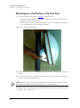
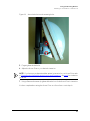
Mounting on a Flat Surface or Vertical Pole . . . . . . . . . . . . . . . . . . . . . . . . . . . . . . . . . 31
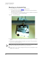
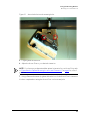
Mounting on a Horizontal Pole . . . . . . . . . . . . . . . . . . . . . . . . . . . . . . . . . . . . . . . . . . . 32
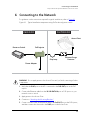
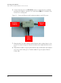
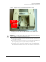
6 Connecting to the Network . . . . . . . . . . . . . . . . . . . . . . . . . . . . . . . . . . . . . . . . . . . . . . . . . 35
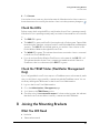
7 Verifying the Installation. . . . . . . . . . . . . . . . . . . . . . . . . . . . . . . . . . . . . . . . . . . . . . . . . . . . 40
Associate a Wireless Client with the Access Point . . . . . . . . . . . . . . . . . . . . . . . . . . . . . 40
Check the LEDs . . . . . . . . . . . . . . . . . . . . . . . . . . . . . . . . . . . . . . . . . . . . . . . . . . . . . . . . . 41
Check the TR069 Status (FlexMaster Management Only) . . . . . . . . . . . . . . . . . . . . . . . 41
8 Joining the Mounting Brackets . . . . . . . . . . . . . . . . . . . . . . . . . . . . . . . . . . . . . . . . . . . . . . 41
What You Will Need . . . . . . . . . . . . . . . . . . . . . . . . . . . . . . . . . . . . . . . . . . . . . . . . . . . . . 41
Mounting on a Flat Surface or Vertical Pole . . . . . . . . . . . . . . . . . . . . . . . . . . . . . . . . . . 42
Mounting on a Horizontal Pole . . . . . . . . . . . . . . . . . . . . . . . . . . . . . . . . . . . . . . . . . . . . 44
9 (Optional) Mounting and Connecting the External Antenna . . . . . . . . . . . . . . . . . . . . . . 46
10 What to Do Next. . . . . . . . . . . . . . . . . . . . . . . . . . . . . . . . . . . . . . . . . . . . . . . . . . . . . . . . . . 49
Change the Administrative Password . . . . . . . . . . . . . . . . . . . . . . . . . . . . . . . . . . . . . . . 49
Configure the Security Settings . . . . . . . . . . . . . . . . . . . . . . . . . . . . . . . . . . . . . . . . . . . . 49
Read Related Documentation . . . . . . . . . . . . . . . . . . . . . . . . . . . . . . . . . . . . . . . . . . . . . 49
11 Professional Installation Instructions . . . . . . . . . . . . . . . . . . . . . . . . . . . . . . . . . . . . . . . . . . 50
Personal Installation . . . . . . . . . . . . . . . . . . . . . . . . . . . . . . . . . . . . . . . . . . . . . . . . . . . . . 50
Installation Location . . . . . . . . . . . . . . . . . . . . . . . . . . . . . . . . . . . . . . . . . . . . . . . . . . . . . 50
External Entenna . . . . . . . . . . . . . . . . . . . . . . . . . . . . . . . . . . . . . . . . . . . . . . . . . . . . . . . . 50
Installation Procedures . . . . . . . . . . . . . . . . . . . . . . . . . . . . . . . . . . . . . . . . . . . . . . . . . . . 50
Warning . . . . . . . . . . . . . . . . . . . . . . . . . . . . . . . . . . . . . . . . . . . . . . . . . . . . . . . . . . . . . . . 50

1
1 About This Getting Started Guide
This Getting Started Guide provides information on how to set up the Ruckus Wireless
ZoneFlex 2741 802.11g Outdoor Access Point on your network. Topics covered in this
guide include installation, basic configuration, and device mounting.
This guide is intended for use by those responsible for installing and setting up network
equipment. Consequently, it assumes a basic working knowledge of local area networking,
wireless networking, and wireless devices.
Related Documentation
In addition to this guide, each Ruckus Wireless ZoneFlex 2741 802.11g Outdoor Access
Point documentation set includes the following:
■ User Guide: Provides detailed information on how to configure the Access Point. The
User Guide is available for download on the Ruckus Wireless Support Web site at:
http://support.ruckuswireless.com/documents
■ Release Notes: Provides late-breaking information about the current software release,
including new features, enhancements, and known issues. If the information in the
Release Notes differs from the information in this guide, follow the instructions in the
Release Notes.
■ Online Help: Accessible from the ZoneFlex Web interface, the Online Help provides
information that helps you configure the Access Point using the Web interface.
Using ZoneDirector or FlexMaster to Manage the
Access Point
If you are planning to use either Ruckus Wireless FlexMaster or Ruckus Wireless ZoneDi-
rector to manage the Access Point, this guide describes the required steps that will enable
the Access Point to report to and communicate with FlexMaster or ZoneDirector success-
fully.
■ To set up the Access Point for management by FlexMaster, refer to “(Optional) Set the
FlexMaster Server Address” on page 22.
■ To set up the Access Point for management by ZoneDirector, refer to “Configuring for
Management by ZoneDirector” on page 12

2
Unpacking the ZoneFlex Access Point
Package Contents
2 Unpacking the ZoneFlex Access Point
1. Open the Access Point package, and then carefully remove the contents.
2. Return all packing materials to the shipping box, and put the box away in a dry location.
3. Verify that all items listed in Package Contents
below are included in the package.
Check each item for damage. If any item is damaged or missing, notify your authorized
Ruckus Wireless sales representative.
Package Contents
A complete Access Point package contains all of the items listed below:
■ ZoneFlex 2741 Outdoor Access Point
■ Box containing the PoE injector (not included in some SKUs)
■ Box containing the power adapter (not included in some SKUs)
■ Two-prong plug adapter (for three-prong wall outlet)
■ Mounting kit (see “Mounting Kit Contents” for details)
■ Bag containing bottom Access Point cover and related accessories (see “Bottom Cover
and Accessories” for details)
■ Service Level Agreement / Limited Warranty Statement
■ Regulatory Statement
■ This Getting Started Guide
WARNING: The Ruckus Wireless PoE injector and power adapter (if supplied with your
Access Point) is for indoor use only. Never mount the PoE injector and power adapter
outdoor with the Access Point.
Mounting Kit Contents
■ Dynamic bracket
■ Static bracket
■ Metal plates (2 pieces)
■ Steel clamp
■ Wall anchors (2 pieces)
■ Hex bolts (4 pieces)
■ Machine screws (8 pieces)
■ Split lock washers (4 pieces)
■ Fender washers (4 pieces)

3
Before You Begin
Prepare the Required Hardware and Tools
Bottom Cover and Accessories
■ Bottom cover of the Access Point
■ DC terminal block
■ Black solid rubber stoppers (2 pieces)
■ Black rubber O-ring
■ Green rubber O-ring
■ White P-clip cable clamp (2 pieces)
■ Machine screws (2 pieces)
■ Machine screws with washers (3 pieces)
3 Before You Begin
Before installing and setting up the Access Point, Ruckus Wireless recommends that you
first complete the following pre-installation tasks.
Prepare the Required Hardware and Tools
You must supply the following tools and equipment:
■ A notebook computer running on Windows XP/2000 and installed with one wireless
802.11b/g network card and one Ethernet card
■ 6mm flathead screwdriver
■ 6mm Phillips screwdriver
■ 10mm ratchet wrench
■ 3mm Phillips screwdriver (if you will be using DC power)
■ Electric drill with 8mm drill bit (if mounting on a flat surface)
NOTE: At the beginning of each procedure, this guide lists the specific tools, accessories,
and equipment that you will need to complete the procedure.

4
Before You Begin
Get to Know the Access Point Features
Get to Know the Access Point Features
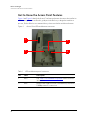
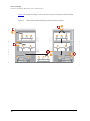
Figure 1 and Figure 2 identify the Access Point features that are relevant to the installation
and mounting instructions that this guide provides. Before you begin the installation
process, Ruckus Wireless recommends that you become familiar with these features.
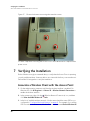
Figure 1. Access Point LEDs and bottom connectors
Table 1. LEDs and bottom panel connectors
No Label Description
1 LEDs See “LED Colors and What They Mean” below for more
information.
2 RJ45 LAN port that supports Power over Ethernet (PoE) and 10/
100Mbps network connections
1
2
3
4

5
Before You Begin
Get to Know the Access Point Features
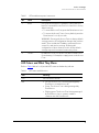
LED Colors and What They Mean
Refer to Tab le 2 below for all possible LED states and what they indicate.
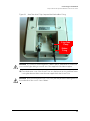
3 Reset Using a pointed object (for example, a pen), press this
button to restart the Access Point or to restore it to factory
default settings:
• To restart the Access Point, press the Reset button once.
• To restore the Access Point to factory default, press the
Reset button for six (6) seconds.
WARNING: Restoring the Access Point to factory default
settings removes all configuration changes that you have
made. These include the IP address, password, access
control list, and wireless settings. Returning the
configuration of these features to their factory default
settings may result in network connectivity issues.
4 12V DC In addition to PoE, you can also use direct current or DC
(from a battery, for example) to supply power to the Access
Point.
Table 2. LED states and behaviors
LED Meaning
OPT Not used in this model
DIR • Off: The Access Point is not being managed by
ZoneDirector (standalone mode).
• Green: The Access Point is being managed by
ZoneDirector.
• Flashing green: The Access Point is being managed
by ZoneDirector, but is currently unable to
communicate with ZoneDirector.
Table 1. LEDs and bottom panel connectors
No Label Description

6
Before You Begin
Get to Know the Access Point Features
AIR • Green: The Access Point is functioning as a mesh
AP (MAP) and the wireless signal to its uplink MAP
is good (> 24dbm).
• Fast flashing green (two flashes every second): The
Access Point is functioning as a mesh AP (MAP) and
the wireless signal to its uplink MAP is poor (<
24dbm).
• Slow flashing green (one flash every two seconds):
Mesh networking is enabled, but the Access Point
cannot find a mesh uplink.
• Off: The Access Point is operating in standalone
mode or, if mesh networking is enabled, the Access
Point is functioning as a root AP (RAP).
WLAN • Green: The wireless LAN (WLAN) service is up and
at least one wireless client is associated with it. If
mesh networking is enabled, there are no downlink
MAPs connected to this Access Point.
• Fast flashing green (two flashes every second): The
WLAN service is up and at least one wireless client
is associated with it. Mesh networking is enabled
and at least one downlink MAP is connected to this
Access Point.
• Slow flashing green (one flash every two seconds):
The WLAN service is up, but no wireless clients are
currently associated with it. Mesh networking is
enabled and at least one downlink MAP is
connected to this Access Point.
• Off: Either the WLAN is down, or it is up but no
wireless clients are currently associated with it. If
mesh networking is enabled, there are no downlink
MAPs connected to this Access Point.
LAN • Green: The LAN port is connected to a 10/100Mbps
device.
• Flashing green: Traffic is passing through the LAN
port.
• Off: The LAN port is not connected to any network
device.
Table 2. LED states and behaviors
LED Meaning

7
Before You Begin
Get to Know the Access Point Features
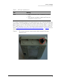
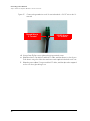
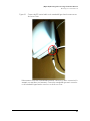
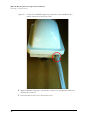
If you want to extend the range of your wireless network, you can connect an external high
gain antenna to the standard N-type radio frequency (RF) antenna connector on the top
panel of the Access Point. The antenna must have a gain of less than 9dBi to comply with
FCC and CE regulations. If you are connecting an external antenna to the Access Point,
refer to “(Optional) Mounting and Connecting the External Antenna”
on page 46 for more
information.
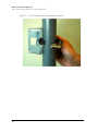
Figure 2. The antenna connector is protected by a black waterproof antenna
connector cover
PWR • Green: The Access Point is connected to a power
source.
• Off: No power is available, or the Access Point is not
connected to a power source.
Table 2. LED states and behaviors
LED Meaning

8
Before You Begin
Perform a Site Survey
Perform a Site Survey
Before installing the Access Point, perform a site survey to determine the optimal Access
Point placement or maximum range, coverage, and network performance. When
performing a site survey, consider the following factors:
■ Data rates: Range is generally inversely proportional to data rates. The maximum radio
range is achieved at the lowest workable data rate. Higher data rates will generally be
achieved at closer distances.
■ Antenna type and placement: Proper antenna configuration is a critical factor in
maximizing radio range. As a general rule, radio range is increased by mounting the
radio higher off of the ground with the Access Point oriented so that the dome is facing
down (for recommended orientation examples, refer to Figure 3
on page 9). If you are
connecting an external antenna to the Access Point, mount the Access Point so that
the external antenna is pointing down.
■ Physical environment: Clear or open areas provide better radio range than closed or
filled areas. The less cluttered the operating environment, the greater the wireless
range.
■ Obstructions, building materials, and sources of interference: Physical obstructions,
such as concrete pillars, steel beams, filing cabinets, buildings, or trees, can block or
hinder wireless communication. Avoid installing the Access Point in a location where
there is an obstruction between sending and receiving devices. A number of machines
and electronic devices that emit radio waves – cranes, wireless phones, microwave
ovens, satellite dishes – interfere with and block wireless signals. Building materials
used in construction also influence radio signal penetration. For example, drywall
construction permits greater range than concrete blocks.
For more Access Point placement guidelines, refer to “Determine the Optimal
Mounting Location and Orientation”.

9
Before You Begin
Determine the Optimal Mounting Location and Orientation
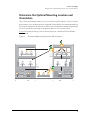
Determine the Optimal Mounting Location and
Orientation
The location and orientation that you choose for the Access Point play a critical role in the
performance of your wireless network. In general, Ruckus Wireless recommends installing
the Access Point away from obstructions and sources of interference and ensuring that the
Access Point’s dome is pointing to the general direction of its wireless clients.
Figure 3
illustrates mounting locations and access point orientations Ruckus Wireless
recommends.
Figure 3. Recommended mounting locations and orientations

10
Before You Begin
Determine the Optimal Mounting Location and Orientation
Figure 4 illustrates mounting locations and access point orientations that should be
avoided.
Figure 4. Not recommended mounting locations and orientations

11
Before You Begin
Become Familiar with the Installation Components
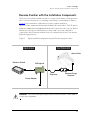
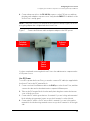
Become Familiar with the Installation Components
The Access Point can be installed in an indoor or outdoor environment, such as an interior
wall or ceiling or the exterior roof overhang of a building or a streetlight pole. Refer to
Figure 5
for the installation components involved in a typical installation.
Take note of the components that must be installed indoor and outdoor. The PoE injector
and power adapter that are shipped with the Access Point are for indoor use only. Ruckus
Wireless also strongly recommends that you form a drip loop on any cable that is
connected to devices that are installed outdoor (for example, the Access Point and the
Ethernet surge protector).
Figure 5. Typical installation components using PoE as the only power source
WARNING: Only trained and qualified personnel should be allowed to install, replace,
or service this equipment.
OUTDOOR
INDOOR
Access Point
Ethernet Surge
Protector
PoE Injector
Router or Switch
Power Adapter
Drip Loop

12
Configuring the Access Point
Configuring for Management by ZoneDirector
WARNING: Installation of the equipment must comply with local and national electrical
codes.
CAUTION: Make sure that you form a 3”-5” drip loop in any cable that is attached to the
Access Point and Ethernet surge protector. This will prevent water from running along the
cables and entering the Access Point, Ethernet surge protector, or the building where the
cables terminate.
CAUTION: Be sure that grounding is available and that it meets local and national
electrical codes. For additional lightning protection, use lightning rods, lightning arrestors,
or surge suppressors.
.
WARNING: The Ruckus Wireless PoE injector (if supplied with your Access Point) is for
indoor use only. Never mount the PoE injector outdoor with the Access Point.
NOTE: If the power outlet in your installation environment is three-pronged, use the two-
prong plug adapter that is shipped with the Access Point.
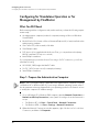
4 Configuring the Access Point
The procedure for completing the Access Point’s essential configuration depends on
whether you want it to be managed by either ZoneDirector or FlexMaster or to operate
as a standalone access point. Refer to the section that is relevant to your deployment:
■ Configuring for Management by ZoneDirector
■ Configuring for Standalone Operation or for Management by FlexMaster
Configuring for Management by ZoneDirector
If ZoneDirector is installed on the network, you can configure the Access Point for
management by ZoneDirector. Simply connect the Access Point to same Layer 2 subnet
as ZoneDirector. When the Access Point starts up, it will discover and register with
ZoneDirector automatically.

13
Configuring the Access Point
Configuring for Management by ZoneDirector
NOTE: In addition to using Layer 2 auto discovery to enable the Access Point to register
with ZoneDirector, you can also use DHCP Option 43 or DNS. For more information, refer
to the ZoneDirector User Guide.
CAUTION: If you use this method, make sure that you do not change the IP address of
ZoneDirector after the AP discovers and registers with it. If you change the ZoneDirector
IP address, the AP will no longer be able to communicate with it and will be unable to
rediscover it.
Before starting this procedure, check the back panel of the Access Point (above the recess
where the bottom connectors are located), and then write down the MAC address of the
Access Point. You will need the MAC address to identify the Access Point on the ZoneDi-
rector Web interface.
1. Connect the Access Point to the same Layer 2 subnet as ZoneDirector. The same Layer
2 subnet means that there should not be any router between the Access Point and
ZoneDirector.
2. Power on the Access Point.
3. Log into ZoneDirector, and then go to the Monitor > Access Points page.
4. Look for the MAC address of the Access Point, and then check its Status column.
• If automatic approval is enabled, the Status column should show Connected.
• If automatic approval is disabled, click the Allow link that is on the same row as the
Access Point’s MAC address. This allows the Access Point to register with ZoneDi-
rector.
When the Status column shows Connected, this indicates that the Access Point has
successfully registered with ZoneDirector and that it can now be moved to its destina-
tion Layer 2 or Layer 3 network.
5. Continue to “Attaching the Mounting Brackets” on page 25.

14
Configuring the Access Point
Configuring for Standalone Operation or for Management by FlexMaster
Configuring for Standalone Operation or for
Management by FlexMaster
What You Will Need
Before starting with the configuration task, make sure that you have the following require-
ments ready:
■ An administrative computer (notebook computer) running on Microsoft Windows
Vista/XP/2000
■ Mozilla Firefox 2.0 (or later) or Microsoft Internet Explorer 6.0 (or later) installed on the
administrative computer
■ One Cat5e UTP (outdoor-rated) solid cable
■ One Ethernet cable
■ PoE injector (if not supplied with the Access Point, you can purchase a third party
802.3af-compliant PoE injector or switch)
■ 6mm Phillips screwdriver
If you are planning to power the Access Point using a 12v DC connection, you will also
need the following:
■ UL1185 (80°, 300V) single shielded DC cable
■ 12v DC, 1A DC power source (for example, a battery)
■ 3mm Phillips screwdriver
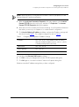
Step 1: Prepare the Administrative Computer
NOTE: The following procedure is applicable if the administrative computer is running
on Windows XP or Windows 2000. If you are using a different operating system, refer to
the documentation that was shipped with your operating system for information on how
to modify the computer’s IP address settings.
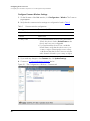
1. On your Windows XP or Windows 2000 computer, open the Network Connections (or
Network and Dial-up Connections) control panel according to how the Start menu is
set up:
• On Windows XP, click Start > Control Panel > Network Connections.
• On Windows 2000, click Start > Settings > Network Connections.
2. When the Network Connections window appears, right-click the icon for Local Area
Connection, and then click Properties.

15
Configuring the Access Point
Configuring for Standalone Operation or for Management by FlexMaster
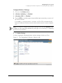
NOTE: Make sure that you configure the Local Area Connection properties, not the
Wireless Network Connection properties.
3. When the Local Area Connection Properties dialog box appears, select Internet
Protocol (TCP/IP) from the scrolling list, and then click Properties. The Internet
Protocol (TCP/IP) Properties dialog box appears.
4. Write down all of the currently active network settings. You will need this information
later when you restore your computer to its current network configuration.
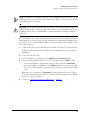
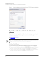
5. Click Use the following IP address, and then configure the IP address settings with
the values listed in Tabl e 3
. For a sample configuration, refer to Figure 6.
You can leave the Alternate DNS server box blank.
6. Click OK to save your changes and close the TCP/IP Properties dialog box.
7. Click OK again to close the Local Area Connection Properties dialog box.
Windows saves the IP address settings that you have configured.
Table 3. Configure your computer’s IP address settings
IP address 192.168.0.22 (or any address in the 192.168.0.x
network—with the exception of 192.168.0.1, which
is already used by the Access Point)
Subnet mask 255.255.255.0
Default gateway 192.168.0.1
Preferred DNS server 192.168.0.1

16
Configuring the Access Point
Configuring for Standalone Operation or for Management by FlexMaster
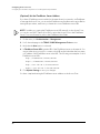
Figure 6. Sample configuration in the Internet Protocol (TCP/IP) Properties dialog box
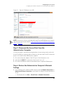
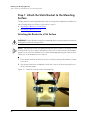
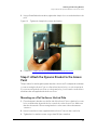
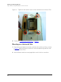
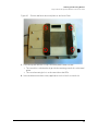
Step 2: Connect the Access Point to the Administrative
Computer
The procedure for connecting the Access Point to the administrative computer depends
on the power source that you will be using. You can do one of the following:
■ Use Power Over Ethernet
■ Use DC Power
NOTE: You only need to connect one type of power source at this point, even if you are
planning to use both PoE and DC power in your final deployment.
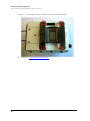
Use Power Over Ethernet
1. Take out the PoE injector and the power adapter from the Access Point package.
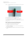
2. Connect one end of an Ethernet cable to the 10/100 DATA IN port on the PoE injector,
and then connect the other end to the administrative computer’s Ethernet port.
3. Connect one end of the other Ethernet cable to the PoE Out port on the PoE injector,
and then connect the other end to the RJ45 port on the Access Point.
La pagina si sta caricando...
La pagina si sta caricando...
La pagina si sta caricando...
La pagina si sta caricando...
La pagina si sta caricando...
La pagina si sta caricando...
La pagina si sta caricando...
La pagina si sta caricando...
La pagina si sta caricando...
La pagina si sta caricando...
La pagina si sta caricando...
La pagina si sta caricando...
La pagina si sta caricando...
La pagina si sta caricando...
La pagina si sta caricando...
La pagina si sta caricando...
La pagina si sta caricando...
La pagina si sta caricando...
La pagina si sta caricando...
La pagina si sta caricando...
La pagina si sta caricando...
La pagina si sta caricando...
La pagina si sta caricando...
La pagina si sta caricando...
La pagina si sta caricando...
La pagina si sta caricando...
La pagina si sta caricando...
La pagina si sta caricando...
La pagina si sta caricando...
La pagina si sta caricando...
La pagina si sta caricando...
La pagina si sta caricando...
La pagina si sta caricando...
La pagina si sta caricando...
La pagina si sta caricando...
La pagina si sta caricando...
-
 1
1
-
 2
2
-
 3
3
-
 4
4
-
 5
5
-
 6
6
-
 7
7
-
 8
8
-
 9
9
-
 10
10
-
 11
11
-
 12
12
-
 13
13
-
 14
14
-
 15
15
-
 16
16
-
 17
17
-
 18
18
-
 19
19
-
 20
20
-
 21
21
-
 22
22
-
 23
23
-
 24
24
-
 25
25
-
 26
26
-
 27
27
-
 28
28
-
 29
29
-
 30
30
-
 31
31
-
 32
32
-
 33
33
-
 34
34
-
 35
35
-
 36
36
-
 37
37
-
 38
38
-
 39
39
-
 40
40
-
 41
41
-
 42
42
-
 43
43
-
 44
44
-
 45
45
-
 46
46
-
 47
47
-
 48
48
-
 49
49
-
 50
50
-
 51
51
-
 52
52
-
 53
53
-
 54
54
-
 55
55
-
 56
56


Ruckus Wireless U2M-OC36600802 Manuale utente
- Categoria
- Router
- Tipo
- Manuale utente
- Questo manuale è adatto anche per
in altre lingue
Documenti correlati
Altri documenti
-
CommScope T350D Guida utente
-
EnGenius ENH500 Manuale utente
-
Senao Networks ENH202 Manuale utente
-
 Tranzeo TR-WMX-3.5 Manuale utente
-
Planet Technology WBS-200N Manuale utente
-
SonicWALL SonicPoint-Ni Getting Started Manual
-
-
-
Ubiquiti UAP-Outdoor 5G Manuale utente
-
CommScope Ruckus Guida utente
