La pagina si sta caricando...

NOVA
ITALIANO pag. 02 / ENGLISH pag. 06
cod. ACG8046
FOTOCELLULE - PHOTOCELLULES
PHOTOCELLS - FOTOZELLEN - FOTOCÉLULAS

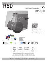
NOTA:
OGNI VOLTA CHE SI ESEGUE UNA NUOVA CONFIGURAZIONE TRAMITE PONTICELLO E’ NECESSARIO TOGLIERE E RIDARE
ALIMENTAZIONE SIA AL TRASMETTITORE CHE AL RICEVITORE.
SCHEMA CON POSIZIONI STANDARD DEI PONTICELLI SCHEMA CON POSIZIONI STANDARD
I
2
2
SETTAGGI E COLLEGAMENTI TRASMETTITORE
J1 AD+ Morsettodialimentazione12-24Vac/dc
AD- Morsettodialimentazione12-24Vac/dc
SYNC Morsettoperfunzionesincronismo
SW1 Microinterruttoridisincronismo
JP1
Ponticello di selezione della portata (15 o 30 metri -
impostazionedifabbrica30m)
DLTX Ledverdepersegnalarelacorrettaalimentazione
SETTAGGI E COLLEGAMENTI RICEVITORE
J2 AD+ Morsettodialimentazione12-24Vac/dc
AD- Morsettodialimentazione12-24Vac/dc
COM Comunedeicontatti
PHOT NC ContattonormalmentechiusoNC
PHOT NO ContattonormalmenteapertoNO
SW2 Microinterruttoridisincronismo
DLRX
Ledrossopersegnalarelacorrettaalimentazione
el’allineamentodelsegnaleinfrarosso
RIFERIMENTI NORMATIVI PER PORTE E CANCELLI
AUTOMATICI
L’installatore deve assicurarsi che l’installazione delle fotocellule NOVA
sia fatta solo in presenza di una ulteriore protezione principale come
specificato nella norma EN12453 al punto 5.5.1. (requisiti generali di
protezione).
RIB NON PUÓ CONSIDERARSI RESPONSABILE PER
EVENTUALI DANNI CAUSATI DA UN USO IMPROPRIO,
ERRONEO O IRRAGIONEVOLE.
POSSIBILITÁ DI IMPIEGO
Le fotocellule NOVA, tecnologicamente all’avanguardia, soddisfano
completamentel’esigenzadiunasicurezzaattivasututtiitipidiaperture
automatiche.
Sonoprodottenellaversionedaparete,dafissaresucolonneinferroo
di altro materiale liscio, o su COLONNINE DI SUPPORTO DEDICATE
cod.ACG8039.
SW1
JP1
DLTX
J1
SW2
DLRX
J2

I
3
3
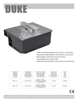
MONTAGGIO
COLLEGAMENTI
N.B.:Primadiposizionareoincollareladimadiforatura(cod.CVA1940)controllarechelasuperficiedicontattosiapulita.
- F
issarelebasiplasticheCPL1312suipilastriosullecolonnineadun’altezzadicirca40÷60cmdalsuoloeadunadistanzamaxdi10cmdallazonadi
convogliamentooschiacciamentoosubitodopol’ingombrodatodaun’eventualecosta.
-TerminateleregolazionimontareloschermoprotettivoCPL1311.
-Installateilricevitoreinombraoinunaposizioneincuiilsolenonpossabattereorizzontalmente.
-Inognicasosiconsigliadiposizionarelefotocelluleallastessaaltezzaeallineatetraloro.
-Perilcorrettoposizionamentodellefotocellulefareriferimentoalmanualediinstallazionedell’operatoreocomunqueallanormaEN12445.
CPL1311 CPL1312
BC08046R
BC08046T
CPL1940
ContattoN.C. da collegare ai
morsettiCOM-PHOT
Alimentazione 12/24V ac/dc
da collegare ai morsetti AD+
AD-presentisulleschedeRIB
ATTENZIONE: Se il led del ricevitore
rimaneaccesoolampeggiaèpossibile
che siano presenti dei disturbi sulla
retedialimentazione.
Vi consigliamo di collegare
elettricamenteversoterralecolonneo
lecolonninedisupportoallefotocellule
al morsetto “A/D-” per proteggere le fotocellule da fonti di
disturbo.
Fate attenzione a non creare corto circuiti quando le fasi di
alimentazione sono invertite!
A/D-
Utilizzare cavi tipo
H05RN-F con fili di
sezione minima 0,75
mm
2
.
Se si supera la
distanza di 10 m tra
fotocellule e quadro
di comando, la
sezione del filo deve
essere aumentata a
1 mm
2
.

I
4
4
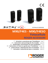
Le fotocellule NOVA possono essere installate vicinissime tra di loro
grazieallafunzionediSINCRONISMO.
IlSINCRONISMOègarantitofinoa4coppiedifotocelluleimpostandoi
microinterruttoriSW1suognitrasmettitoreTXeSW2suogniricevitore
RXcomedadisegnosottostante.
Eseguire inoltre il collegamento dei morsetti SYNC sui trasmettitori
presentinell’impiantotradilorocomedaschema,inmododagenerare
ilsincronismo.
TX3 RX3
TX2 RX2
TX1 RX1
TX4 RX4
NOTA:perunacorrettasincronizzazione,almeno una coppia di fotocellule deve avere entrambi i dip switch in OFF (vedi
TX1 e RX1).
Incasodialimentazionea12-24Vaceseguireicollegamenticomedaschema.
ATTENZIONE:sesiinvertonolealimentazionianchesuunsoloTXoRXlasincronianonvieneeseguitacorrettamente.
Alimentazione 12/24V ac/dc
da collegare ai morsettiAD+
AD-presentisulleschedeRIB

5
5
PORTATA
Èpossibiledeciderelaportatadellefotocelluleposizionandounponticello
sul/suitrasmettitore/i.
Ponticello JP1 con portata regolata a 30 m (impostazione di fabbrica)
Ponticello JP1 con portata regolata a 15 m
-
Dopo aver fissato le basi plastiche delle fotocellule NOVA, inserire le
schedeelettronichenelleappositesedipredispostesullebasiequindi
fissarleconlevitiindotazione.
-Alimentarelefotocellule.
-IlledverdedeltrasmettitoreTXsideveaccendere.
-
IlledrossodelricevitoreRXsiaccendeselefotocellulesonoallineate
tradiloro.
Seilledrossononsiaccendeeseguirel’allineamentocomeindicato.
ALLINEAMENTO
-
Le fotocellule NOVA vengono consegnate con allineamento centrale,
tuttavia in caso di necessità è possibile eseguire una regolazione dei
gruppiotticideltrasmettitoreedelricevitore(+90°/-90°inorizzontalee
+5°/-5°inverticale).
-
Ad allineamento eseguito il led rosso presente sul ricevitore si deve
accenderefissoperindicarelacorrettaricezionedelsegnaleinfrarosso
generatodaltrasmettitore.
Seilledrossolampeggia=>significacheilsegnaleèdeboleequindi
l’allineamentoèdaottimizzarefinoadottenereilledrossoaccesofisso.
-
Seiltrasmettitoreedilricevitoresonomontatiadunadistanzainferiore
a10metri,consigliamodiposizionareilponticelloJP1comeindicatonel
paragrafo“PORTATA”.
-
Montareglischermiprotettivi.
VERIFICA DEL FUNZIONAMENTO
FUNZIONAMENTO CON SINCRONISMO:
-
Interporreun’ostacolodavantialtrasmettitore.
-
Verificarecheilledrossodelcorrispondentericevitoresispenga.
FUNZIONAMENTO SENZA SINCRONISMO:
-
Interporre un’ostacolo prima davanti al trasmettitore e poi davanti al
ricevitore.
-
Verificarecheilledrossodelricevitoresispengainentrambiicasi.
CARATTERISTICHE TECNICHE
-ALIMENTAZIONE
12-24Vacdc(Verificate la
compatibilità con l’alimentazione
fornita dal quadro elettronico)
-ASSORBIMENTOMASSIMORX 110mA
-ASSORBIMENTOMASSIMOTX 60mA
-PORTATARELE’ 1A-30Vdc
-LUNGHEZZAD’ONDASEGNALEINFRAROSSO890nm
-LEDVERDETRASMETTITORE acceso=>èalimentato.
-LEDROSSORICEVITORE
acceso=>èallineato.(N.B. a
taratura avvenuta si spegne
quando si interpone un
ostacolo).
-PORTATASELEZIONABILE
15÷30m(conbuonecondizioni
atmosferiche)N.B.: La portata
si può ridurre in presenza di
fenomeni atmosferici quali
nebbia, pioggia, polvere, ecc.
-TEMPERATURADILAVORO -20°C÷+60°C
-CONTENITORE
ESTERNOINPOLICARBONATO,
INTERNOINABS.
-GRADODIPROTEZIONE IP44
-DIMENSIONI 150x45x41
-PESO 0,300kg
I
OPTIONAL
COPPIA COLONNINE NOVA
H=0,5m cod.ACG8039
H
L

6
6
G
B
6
6
NOTE:
EACH TIME A NEW JUMPER CONFIGURATION IS USED IT IS NECESSARY TO TURN OFF AND TURN ON POWER TO BOTH THE
TRANSMITTER AND THE RECEIVER.
STANDARD POSITIONS JUMPERS STANDARD POSITIONS
SETTINGS AND TRANSMITTER CONNECTIONS
J1 AD+ Feedterminal12-24Vac/dc
AD- Feedterminal12-24Vac/dc
SYNC Functionsynchronizationterminal
SW1 Micro-switchesforsynchronization
JP1
Limitcapacityjumper(15or30meters-factorysetting
30m)
DLTX GreenLEDindicatingcorrectpower
SETTINGS AND RECEIVER CONNECTIONS
J2 AD+ Feedterminal12-24Vac/dc
AD- Feedterminal12-24Vac/dc
COM Contactsystem
PHOT NC ContactnormallyclosedNC
PHOT NO ContactnormallyopenNO
SW2 Micro-switchesforsynchronization
DLRX
Red LED indicating correct power and infrared
signalpower
REFERENCE TO STANDARDS FOR AUTOMATIC GATES
AND DOORS
The installer must ensure that the installation of the NOVA photocells
is performed only in the presence of further protection as specified by
standardEN12453in5.5.1.(generalprotectionrequirements).
RIB MAY NOT BE HELD RESPONSIBLE FOR DAMAGES
CAUSED BY IMPROPER, WRONG OR UNREASONABLE USE.
USES
NOVAphotocellsaretechnologicallyadvancedandcompletelymeetthe
activesecuritydemandsofalltypesofautomaticopeningsystems.
Theyareproducedinversionsforwallmounting,formountingtocolumns
ofironorothersmoothmaterial,orondedicatedSUPPORTCOLUMNS
cod.ACG8039.
SW1
JP1
DLTX
J1
SW2
DLRX
J2

7
7
7
7
G
B
MOUNTING
CONNECTIONS
N.B.:Beforeplacingthedrillingtemplate(cod.CVA1940)makesurethatthecontactsurfaceisclean.
-
AffixtheplasticbasesCPL1312tothepillarsorcolumnsabout40÷60cmfromthegroundandatamaximumdistanceof10cmfromtheconveyance
orpressureareaorimmediatelyoutofrangeofanyprotrudingedge.
-AfteradjustmentattachtheprotectivecasingCPL1311.
-Installthereceiverinashadedareaorinapositionnotexposedtohorizontalsunlight.
-Ineverycaseitisadvisabletoplacethephotocellsatthesameheightandinlinewitheachother.
-ForthecorrectpositioningofthephotocellsrefertotheuserinstallationmanualortostandardEN12445.
CPL1311 CPL1312
BC08046R
BC08046T
CPL1940
Contact N.C. to connect to
terminalsCOM-PHOT
Power 12/24V ac/dc to
connecttoterminalsAD+AD-
ontheRIBcontrolpanels
ATTENTION:Incasethereceiverled
remainslit,malfunctioningofthemain
supplyissuspected.
It is advisable to connect electrically
the photocells stands to the contact
“A/D-”, to shield the photocells from
externalnoise.
Be careful not to short circuit the system when the supply
phases are inverted!
A/D-
Use H05RN-F
cables, with a
minimum section of
0,75 mm
2
.
If you exceed the
distance of 10 m
between photocells
and control panel,
the wire section
must be increased
to 1 mm
2
.

8
8
G
B
8
8
NOVA photocells may be installed very close together thanks to
SYNCHRONIZATION.
SYNCHRONIZATION is guaranteed for up to 4 pairs of photocells by
setting the SW1 micro-switches on every TX transmitter and SW2 on
everyRXreceiverasshowninthediagrambelow.
ConnecttheSYNCterminalsandthetransmittersinthesystemtoeach
otherasinthediagramtocreatesynchronization.
TX3 RX3
TX2 RX2
TX1 RX1
TX4 RX4
NOTE: for the correct functioning of the syncronization, at least one of the pair of photocells must have both the dip
switches in the OFF mode (see TX1 and RX1).
Incasethepowersupplyis12-24Vac,thewiringmustbecarriedoutasperdiagram.
ATTENTION:ifthepowersupplyisinvertedevenjustonTXorRX,thesyncronizationwillnotbecarriedoutcorrectly.
Power 12/24V ac/dc to
connecttoterminalsAD+AD-
ontheRIBcontrolpanels

9
9
9
9
G
B
RANGE
Itispossibletoadjusttherangeofthephotocellsbyplacingajumperon
thetransmitters.
Jumper JP1 with a range of 30 m (factory setting)
Jumper JP1 with a range of 15 m
- AfteraffixingtheplasticbasesoftheNOVAphotocells,insertthecircuit
boards into the proper places on the bases and attach them with the
suppliedscrews.
- Powertothephotocells.
- ThegreenLEDoftheTXtransmittersshouldcomeon.
- The red LED of the RX receiver comes on when the photocells are
alignedtoeachother.
IftheredLEDdoesnotcomeonfollowthealignmentprocedureindicated.
ALIGNMENT
-NOVA photocells are shipped with central alignment, however, if
necessary,itispossibletoadjusttheopticalunitsofthetransmitterand
receiver(+90°/-90°horizontallyand+5°/-5°vertically).
-AfteralignmenttheredLEDonthereceivershouldbeconstant,indicating
correctreceptionoftheinfraredsignalgeneratedbythetransmitter.
IftheredLEDflashes=>itmeansthatthesignalisweakandthereforthe
alignmentmustbeadjusteduntiltheredLEDisconstant.
-Ifthetransmitterandthereceiveraremountedatadistanceoflessthan
10 meters from each other, we advise positioning the jumper JP1 as
indicatedintheparagraph“RANGE”.
-Mounttheprotectivecasings.
SYSTEM CHECK
SYNCHRONIZATION:
-Placeanobjectinfrontofthetransmitter.
-CheckthattheredLEDofthecorrespondingreceiverturnsoff.
NO SYNCHRONIZATION:
-Placeanobjectinfrontofthetransmitterandtheninfrontofthereceiver.
-CheckthattheredLEDofthereceiversisoffinbothcases
.
TECHNICAL SPECIFICATIONS
-POWER
12-24Vac/dc(check
compatibility of the power
supplied by the electric panel)
-MAXIMUMABSORPTIONRX 110mA
-MAXIMUMABSORPTIONTX 60mA
-RELAYRANGE 1A-30Vdc
-INFRAREDSIGNALWAVELENGTH 890nm
-GREENLEDTRANSMITTER on=>power.
-REDLEDRECEIVER
on=>power(N.B. when
adjusted it turns off when an
object is placed in front of it)
-ADJUSTABLERANGE
15÷30m(ingoodweather
conditions)N.B.: Range may
be reduced in bad weather
conditions such as fog, rain,
dust, etc.
-WORKINGTEMPERATURE -20°C÷+60°C
-CONTAINER
EXTERIORIN
POLYCARBONATE,INTERIOR
INABS.
-PROTECTIONLEVEL IP44
-DIMENSIONS 150x45x41
-WEIGHT 0,300kg
ACCESSORIES
PAIR OF COLUMNS for NOVA
H=0,5m codeACG8039
H
L

NOTES
10
10

DICHIARAZIONE DI CONFORMITÁ - DÉCLARATION DE CONFORMITÉ
DECLARATION OF COMPLIANCE - DECLARACIÓN DE CONFORMIDAD
Dichiariamo sotto la nostra responsabilità che NOVA è conforme alle seguenti norme e Direttive:
NOVA se conforme aux normes suivantes:
We declare under our responsibility that NOVA is conform to the following standards:
Wir erklaeren das NOVA den folgenden EN-Normen entspricht:
Declaramos bajo nuestra responsabilidad que
NOVA
ed conforme a la siguientes normas y disposiciones:
Come richiesto dalle seguenti Direttive - Conformément aux Directives
As is provided by the following Directives - Gemaß den folgenden Richtlinien
Tal y como requerido por las siguientes Disposiciones:
Il presente prodotto non può funzionare in modo indipendente ed è destinato ad essere incorporato in un impianto costituito da ulteriori elementi.
Rientra perciò nell’Art. 6 paragrafo 2 della Direttiva 2006/42/CE (Macchine) e successive modifiche, per cui segnaliamo il divieto di messa in
servizio prima che l’impianto sia stato dichiarato conforme alle disposizioni della Direttiva.
Le présent dispositif ne peut fonctionner de manière indépendante, étant prévu pour être intégré à une installation constituée d’autres éléments. Aussi
rentre-t-il dans le champ d’application de l’art. 6, paragraphe 2 de la Directive machines 2006/42/CEE et de ses modifications successives. Sa mise
en service est interdite avant que l’installation ait été déclarée conforme aux dispositions prévues par la Directive.
This product can not work alone and was designed to be fitted into a system made up of various other elements. Hence, it falls within Article 6,
Paragraph 2 of the EC-Directive 2006/42 (Machines) and following modifications, to which respect we point out the ban on its putting into service
before being found compliant with what is provided by the Directive.
Dieses Produkt kann nicht allein funktionieren und wurde konstruiert, um in einen von anderen Bestandteilen zusammengesetzten System eingebaut
zu werden. Das Produkt fällt deswegen unter Artikel 6, Paragraph 2 der EWG-Richtlinie 2006/42 (Maschinen) und folgenden.
El presente producto no puede funcionar de manera independiente y está destinado a ser incorporado en un equipo constituido por ulteriores
elementos. Entra por lo tanto en el Art. 6 párrafo 2 de la Directiva 2006/42/CEE (Máquinas) y sucesivas modificaciones, por lo que señalamos la
prohibición de puesta en servicio antes de que el equipo haya sido declarado conforme con las disposiciones de la Directiva.
Legal Representative
(Rasconi Antonio)
EN 12978 2009
EN 55014-1 2000
EN 55014-2 1997
EN 60335-1 2008
EN 61000-3-2 2007
EN 61000-3-3 1997
EN 61000-6-1 2007
EN 61000-6-2 2006
EN 61000-6-3 2007
EN 61000-6-4 2007
2006/95/CE 2004/108/CE
11
11
R.I.B. S.r.l.
25014 Castenedolo - Brescia - Italy
Via Matteotti, 162
Tel. ++39.030.2135811
Fax ++39.030.21358279 - 21358278
www.ribind.it - [email protected]
AZIENDA CON SISTEMA
DI QUALITÀ CERTIFICATO
DA DNV
COMPANY WITH QUALITY
SYSTEM CERTIFIED
BY DNV

NOVA
Cod. CVA1968 - 20032012 - Rev. 04
Questo prodotto è stato completamente progettato e costruito in Italia · Ce produit a été complètement développé et fabriqué en Italie · This product has been completely
developed and built in Italy · Dieses Produkt wurde komplett in Italien entwickelt und hergestellt · Artìculo totalmente proyectado y producido en Italia
ACG8047
NOVA WIRELESS
Portatasegnaleinfrarosso25m.
Duratabatterie3anni.
Sincronismo disponibile su 2 diverse frequenze
selezionabili.
ACG8047
NOVA WIRELESS
Infraredsignalrange25m.
Batterylife3years.
Synchronizationavailableon2differentfrequencyadjustments.
ACG8047
NOVA WIRELESS
Alcancedelaseñalinfrarroja25m.
Duracióndelasbaterías3años.
Sincronismodisponiblesobre2frecuenciasseleccionablesdistintas.
ACG8047
NOVA WIRELESS
Portéedufaisceauinfrarouge25m.
Duréedeviedespiles3ans.
Synchronismedisponiblesur2fréquencessélectionnables.
ACG8047
NOVA WIRELESS
ReichweitedesInfrarotsignals25m.
Batterielebensdauer3Jahre.
Synchronisationverfügbarfür2unterschiedlicheFrequenzanpassungen.
ACG8037
NOVA WI-FI - Patent EP10711742 - EP2347398
NOVA Wi-Fi è la prima fotocellula al mondo
completamente via radio dove sia il trasmettitore che
il ricevitore funzionano a batterie. Non è necessario
quindi nessun collegamento filare alla centrale.
Portatasegnaleinfrarosso25m.
Portatasegnaleradio20m.
Duratabatterie3anni.
ACG8037
NOVA WI-FI - Patent EP10711742 - EP2347398
NOVA Wi-Fi is the first radio controlled photocell in the world with
battery operated transmitter and receiver. No wire connections
necessary.
Infraredsignalrange25m.
Radiosignalrange20m.
Batterylife3years.
ACG8037
NOVA WI-FI - Patent EP10711742 - EP2347398
NOVA Wi-Fi es la primera fotocélula del mundo que funciona
completamente vía radio, donde tanto el transmisor como el receptor
funcionan con baterías. Por ello, no requiere ningún tipo de conexión
cableada a la central.
Alcancedelaseñalinfrarroja25m.
Alcancedelaseñalradio20m.
Duracióndelasbaterías3años.
ACG8037
NOVA WI-FI - Patent EP10711742 - EP2347398
NOVA Wi-Fi est la première photocellule totalement sans fil au
monde pour laquelle l’émetteur et le récepteur fonctionnent sur piles.
Aucune connexion filaire n’est donc nécessaire.
Portéedufaisceauinfrarouge25m.
Portéedusignalwifi20m.
Duréedeviedespiles3ans.
ACG8037
NOVA WI-FI - Patent EP10711742 - EP2347398
NOVA Wi-Fi ist die erste durch Funk ferngesteuerte Fotozelle der
Welt mit einem batteriebetriebenem Sender und Empfänger. Keine
Drahtverbindung erforderlich.
ReichweitedesInfrarotsignals25m.
ReichweitedesFunksignals20m.
Batterielebensdauer3Jahre.
Altri dispositivi della serie NOVA - Autres appareils de la série NOVA: - Other devices in the NOVA series: - Andere
Geräte aus der NOVA-Serie: - Otros dispositivos de serie NOVA:
25014 CASTENEDOLO (BS) - ITALY
Via Matteotti, 162
Tel. +39.030.2135811
Fax +39.030.21358279
www.ribind.it - [email protected]
/