Yamaha 2003 FJR1300 Manuale utente
- Categoria
- Motociclette
- Tipo
- Manuale utente
Questo manuale è adatto anche per

2003
FJR1300(R)
FJR1300A(R)
5JW1-AE4
SUPPLEMENTARY
SERVICE MANUAL


FOREWORD
This Supplementary Service Manual has been prepared to introduce new service and data for the
FJR1300(R)/FJR1300A(R) 2003. For complete service information procedures it is necessary to
use this Supplementary Service Manual together with the following manuals.
FJR1300(N) 2001 SERVICE MANUAL: 5JW1-AE1
FJR1300(P) 2002 SUPPLEMENTARY SERVICE MANUAL: 5JW1-AE2
FJR1300(R)/FJR1300A(R) 2003
SUPPLEMENTARY
SERVICE MANUAL
© 2003 by Yamaha Motor Co., Ltd.
First edition, February 2003
All rights reserved.
Any reproduction or unauthorized use
without the written permission of
Yamaha Motor Co., Ltd.
is expressly prohibited.

EAS00002
NOTICE
This manual was produced by the Yamaha Motor Company, Ltd. primarily for use by Yamaha deal-
ers and their qualified mechanics. It is not possible to include all the knowledge of a mechanic in
one manual. Therefore, anyone who uses this book to perform maintenance and repairs on Yamaha
vehicles should have a basic understanding of mechanics and the techniques to repair these types
of vehicles. Repair and maintenance work attempted by anyone without this knowledge is likely to
render the vehicle unsafe and unfit for use.
Yamaha Motor Company, Ltd. is continually striving to improve all of its models. Modifications and
significant changes in specifications or procedures will be forwarded to all authorized Yamaha deal-
ers and will appear in future editions of this manual where applicable.
NOTE:
@
Designs and specifications are subject to change without notice.
EAS00004
IMPORTANT MANUAL INFORMATION
Particularly important information is distinguished in this manual by the following.
The Safety Alert Symbol means ATTENTION! BECOME ALERT! YOUR
SAFETY IS INVOLVED!
Failure to follow WARNING instructions could result in severe injury or death to
the motorcycle operator, a bystander or a person checking or repairing the
motorcycle.
A CAUTION indicates special precautions that must be taken to avoid damage
to the motorcycle.
A NOTE provides key information to make procedures easier or clearer.
WARNING
CAUTION:
NOTE:

EAS00007
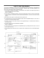
HOW TO USE THIS MANUAL
This manual is intended as a handy, easy-to-read reference book for the mechanic. Comprehensive
explanations of all installation, removal, disassembly, assembly, repair and check procedures are
laid out with the individual steps in sequential order.
1
The manual is divided into chapters. An abbreviation and symbol in the upper right corner of
each page indicate the current chapter.
Refer to “SYMBOLS”.
2
Each chapter is divided into sections. The current section title is shown at the top of each page,
except in chapter 3 (“PERIODIC CHECKS AND ADJUSTMENTS”), where the sub-section title(s)
appears.
3
Sub-section titles appear in smaller print than the section title.
4
To help identify parts and clarify procedure steps, there are exploded diagrams at the start of
each removal and disassembly section.
5
Numbers are given in the order of the jobs in the exploded diagram. A circled number indicates a
disassembly step.
6
Symbols indicate parts to be lubricated or replaced.
Refer to “SYMBOLS”.
7
A job instruction chart accompanies the exploded diagram, providing the order of jobs, names of
parts, notes in jobs, etc.
8
Jobs requiring more information (such as special tools and technical data) are described sequen-
tially.

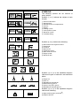
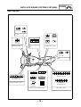
EAS00008
SYMBOLS
The following symbols are not relevant to
every vehicle.
Symbols
1
to
9
indicate the subject of each
chapter.
1
General information
2
Specifications
3
Periodic checks and adjustments
4
Chassis
5
Engine
6
Cooling system
7
Fuel injection system
8
Electrical system
9
Troubleshooting
Symbols
0
to
G
indicate the following.
0
Serviceable with engine mounted
A
Filling fluid
B
Lubricant
C
Special tool
D
Tightening torque
E
Wear limit, clearance
F
Engine speed
G
Electrical data
Symbols
H
to
M
in the exploded diagrams
indicate the types of lubricants and lubrication
points.
H
Engine oil
I
Gear oil
J
Molybdenum disulfide oil
K
Wheel bearing grease
L
Lithium soap base grease
M
Molybdenum disulfide grease
Symbols
N
to
O
in the exploded diagrams
indicate the following.
N
Apply locking agent (LOCTITE
®
)
O
Replace the part
12
34
56
78
90
AB
CD
EFG
HIJ
KLM
NO
GEN
INFO
SPEC
CHK
ADJ
CHAS
ENG
COOL
FI
–+
ELEC
TRBL
SHTG
T
R
.
.
E
G
M
B
LS
M
LT
New

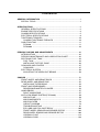
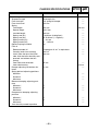
CONTENTS
GENERAL INFORMATION
..............................................................................1
SPECIAL TOOLS ......................................................................................1
SPECIFICATIONS
............................................................................................2
GENERAL SPECIFICATIONS ..................................................................2
ENGINE SPECIFICATIONS ......................................................................3
CHASSIS SPECIFICATIONS ....................................................................5
ELECTRICAL SPECIFICATIONS .............................................................8
TIGHTENING TORQUES .......................................................................10
CHASSIS TIGHTENING TORQUES ..................................................10
CABLE ROUTING ...................................................................................11
FJR1300 ..............................................................................................11
FJR1300A ...........................................................................................23
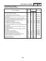
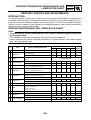
PERIODIC CHECKS AND ADJUSTMENTS
..................................................42
INTRODUCTION .....................................................................................42
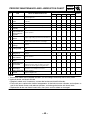
PERIODIC MAINTENANCE AND LUBRICATION CHART .....................42
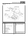
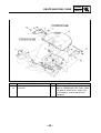
SEATS AND FUEL TANK .......................................................................44
FUEL TANK ........................................................................................44
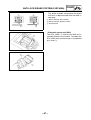
INSTALLING THE FUEL PUMP .........................................................46
COWLINGS AND COVERS ....................................................................47
COWLINGS .........................................................................................47
ELECTRICAL SYSTEM ..........................................................................50
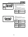
ADJUSTING THE HEADLIGHT BEAMS ............................................50
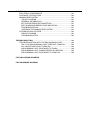
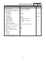
CHASSIS
........................................................................................................51
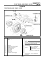
FRONT WHEEL AND BRAKE DISCS ....................................................51
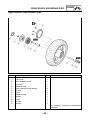
REAR WHEEL AND BRAKE DISC .........................................................52
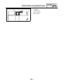
INSTALLING THE BEARING ..............................................................53
FRONT AND REAR BRAKES .................................................................54
REAR BRAKE MASTER CYLINDER ..................................................54
HANDLEBARS ........................................................................................57
RIGHT HANDLEBAR ..........................................................................57
ANTI-LOCK BRAKE SYSTEM (FJR1300A) ............................................58
ABS OUTLINE ....................................................................................58
ABS COMPONENTS ..........................................................................77
ABS COUPLERS ................................................................................78
CIRCUIT DIAGRAM ............................................................................79
TROUBLESHOOTING ........................................................................81
ECU (ABS) AND FAIL-SAFE RELAY ...............................................100
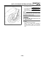
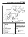
FRONT WHEEL SENSOR AND SENSOR ROTOR .........................104
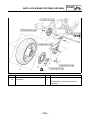
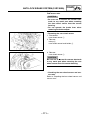
REAR WHEEL SENSOR AND SENSOR ROTOR ...........................109
HYDRAULIC UNIT ............................................................................113
HYDRAULIC ABS .............................................................................120

ELECTRICAL ...............................................................................................131
ELECTRICAL COMPONENTS .............................................................131
CHECKING THE SWITCHES ...............................................................133
IMMOBILIZER SYSTEM .......................................................................135
CIRCUIT DIAGRAM ..........................................................................135
GENERAL INFORMATION ...............................................................136
KEY CODES REGISTRATION METHOD..........................................137
SELF-DIAGNOSIS ERROR CODE INDICATION..............................140
TROUBLESHOOTING ......................................................................141
CHECKING THE IMMOBILIZER SYSTEM .......................................142
ACCESSORY BOX SYSTEM ...............................................................145
CIRCUIT DIAGRAM ..........................................................................145
TROUBLESHOOTING ......................................................................146
TROUBLESHOOTING ..................................................................................148
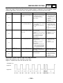
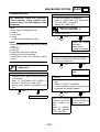
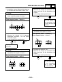
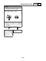
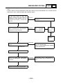
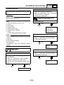
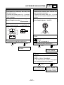
TROUBLESHOOTING WITH THE ABS WARNING LIGHT ..................148
ONLY THE ABS WARNING LIGHT DOES NOT COME ON ............148
ALL INDICATORS DO NOT COME ON ...........................................148
ABS WARNING LIGHT CONTINUES TO FLASH ............................148
ABS WARNING LIGHT FLASHES EVERY 0.5 SECOND ................148
ABS WARNING LIGHT CONTINUES TO COME ON .......................148
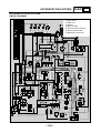
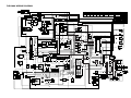
FJR1300A WIRING DIAGRAM
FJR1300 WIRING DIAGRAM

– 1 –
GEN
INFO
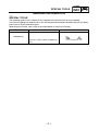
SPECIAL TOOLS
GENERAL INFORMATION
EB104000
SPECIAL TOOLS
The following special tool is necessary for complete and accurate tune-up and assembly.
Use only the appropriate special tool as this will help prevent damage caused by the use of inappro-
priate tools or improvised techniques.
When placing an order, refer to the list provided below to avoid any mistakes.
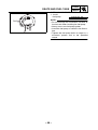
Tool No. Tool name/Function Illustration
90890-03149
Test coupler adaptor
This tool is used to check the ABS diag-
nosis.

– 2 –
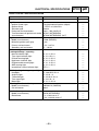
SPEC
SPECIFICATIONS
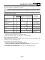
GENERAL SPECIFICATIONS
Item Standard Limit
Model code
FJR1300: 5JWA (for Europe)
5JWB (for F)
5JWC (for Oceania)
FJR1300A: 5VS1 (for Europe)
5VS2 (for F)
5VS3 (for Oceania)
----
----
----
----
----
----
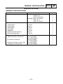
Dimensions
Overall length 2,195 mm ----
Overall width 760 mm ----
Overall height 1,435 mm ----
Seat height 805 mm ----
Wheelbase 1,515 mm ----
Minimum ground clearance 135 mm ----
Minimum turning radius 3,100 mm ----
Weight
Wet (with oil and a full fuel tank) 275 kg (FJR1300)
282 kg (FJR1300A)
----
----
Dry (without oil and fuel) 244 kg (FJR1300)
251 kg (FJR1300A)
----
----
Maximum load (total of cargo, rider,
passenger, and accessories)
201 kg (FJR1300)
194 kg (FJR1300A)
----
----
GENERAL SPECIFICATIONS

– 3 –
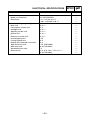
SPEC
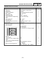
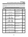
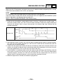
ENGINE SPECIFICATIONS
ENGINE SPECIFICATIONS
Item Standard Limit
Engine
Engine type Liquid-cooled, 4-stroke, DOHC ----
Displacement 1,298 cm
3
----
Cylinder arrangement Forward-inclined parallel 4-cylinder ----
Bore × stroke 79.0 × 66.2 mm ----
Compression ratio 10.8 : 1 ----
Engine idling speed 1,000 ~ 1,100 r/min ----
Vacuum pressure at engine idling
speed
33.3 kPa (250 mmHg) ----
Water temperature 100 ~ 105 °C ----
Oil temperature 80 ~ 90 °C ----
Standard compression pressure
(at sea level)
1,600 kPa (16 kg/cm
2
,
16 bar)
at 400 r/min
----
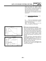
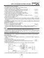
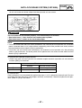
Engine oil
Lubrication system Wet sump ----
Recommended oil
SAE 20W-40 SE
SAE 10W-40 SE
API service SE, SF, SG type or higher
----
----
----
Quantity
Total amount 4.9 L ----
Without oil filter cartridge replace-
ment
3.8 L ----
With oil filter cartridge replacement 4 L ----
Oil pressure (hot) 30 kPa (0.30 kg/cm
2
,
0.30 bar)
at 1,000 r/min
----
Relief valve operating pressure 480 ~ 560 kPa
(4.80 ~ 5.60 kg/cm
2
,
4.80 ~ 5.60 bar)
----
-20 -10 0
10
20 30
40
50 ˚C
SAE 15W-40
SAE 20W-40
SAE 10W-40

– 4 –
SPEC
ENGINE SPECIFICATIONS
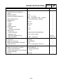
Cooling system
Radiator capacity (including all
routes)
3.2 L ----
Radiator capacity 1.03 L ----
Radiator cap opening pressure 93.3 ~ 122.7 kPa
(0.93 ~ 1.23 kg/cm
2
,
0.93 ~ 1.23 bar)
----
Valve relief pressure 4.9 kPa (0.05 kg/cm
2
,
0.05 bar) ----
Radiator core
Width 360 mm ----
Height 295.8 mm ----
Depth 27 mm ----
Coolant reservoir
Capacity 0.25 L ----
<From low to full level> 0.15 L ----
Water pump
Water pump type Single-suction centrifugal pump ----
Reduction ratio 75/48 × 25/28 (1.395) ----
Maximum impeller shaft tilt ---- 0.15 mm
Measurement B 24.997 ~ 25.097 mm 23.997 mm
Fuel pump
Pump type Electrical ----
Model (manufacturer) 5JW (DENSO) ----
Maximum consumption amperage 5.5 A ----
Output pressure 294 kPa (2.94 kg/cm
2
,
2.94 bar) ----
Throttle bodies
Model (manufacturer) × quantity 42EHS (MIKUNI) × 4 ----
Intake vacuum pressure 33.3 kPa (250 mmHg) ----
Throttle cable free play (at the flange
of the throttle grip)
3 ~ 5 mm ----
ID mark 5JW1 40 ----
Item Standard Limit

– 5 –
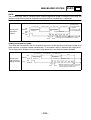
SPEC
CHASSIS SPECIFICATIONS
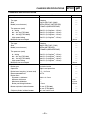
CHASSIS SPECIFICATIONS
Item Standard Limit
Front tire
Tire type Tubeless ----
Size 120/70 ZR17 M/C (58W) ----
Model (manufacturer) MEZ4J FRONT (METZELER)/
BT020F N (BRIDGESTONE)
----
Tire pressure (cold)
0 ~ 90 kg 250 kPa (2.5 kgf/cm
2
, 2.5 bar) ----
90 ~ 201 kg (FJR1300) 250 kPa (2.5 kgf/cm
2
, 2.5 bar) ----
90 ~ 194 kg (FJR1300A) 250 kPa (2.5 kgf/cm
2
, 2.5 bar) ----
High-speed riding 250 kPa (2.5 kgf/cm
2
, 2.5 bar) ----
Minimum tire tread depth ---- 1.6 mm
Rear tire
Tire type Tubeless ----
Size 180/55 ZR17 M/C (73W) ----
Model (manufacturer) MEZ4J (METZELER)/
BT020R N (BRIDGESTONE)
----
Tire pressure (cold)
0 ~ 90 kg 250 kPa (2.5 kgf/cm
2
, 2.5 bar) ----
90 ~ 201 kg (FJR1300) 290 kPa (2.9 kgf/cm
2
, 2.9 bar) ----
90 ~ 194 kg (FJR1300A) 290 kPa (2.9 kgf/cm
2
, 2.9 bar) ----
High-speed riding 250 kPa (2.5 kgf/cm
2
, 2.5 bar) ----
Minimum tire tread depth ---- 1.6 mm
Front brakes
Brake type Dual-disc brake ----
Operation Right-hand operation ----
Brake lever free play (at lever end) 7.5 ~ 16.5 mm ----
Recommended fluid DOT 4 ----
Brake discs
Diameter × thickness 320.0 × 4.5 mm ----
Minimum thickness ---- 4 mm
Maximum deflection ---- 0.1 mm
Brake pad lining thickness 5.5 mm 0.5 mm
Master cylinder inside diameter 15 mm (FJR1300)
16 mm (FJR1300A)
----
----
Caliper cylinder inside diameter 30.2 mm and 27 mm ----

– 6 –
SPEC
CHASSIS SPECIFICATIONS
Front suspension
Suspension type Telescopic fork ----
Front fork type Coil spring/oil damper ----
Front fork travel 135 mm ----
Spring
Free length 264 mm 259 mm
Spacer length 149.5 mm ----
Installed length 249 mm ----
Spring rate (K1) 7.84 N/mm (0.8 kgf/mm) ----
Spring rate (K2) 10.78 N/mm (1.1 kgf/mm) ----
Spring stroke (K1) 0 ~ 91 mm ----
Spring stroke (K2) 91 ~ 135 mm ----
Optional spring available No ----
Fork oil
Recommended oil Suspension oil “01” or equivalent ----
Quantity (each front fork leg) 664 cm
3
----
Level (from the top of the inner
tube, with the inner tube fully com-
pressed, and without the fork
spring)
104 mm ----
Inner tube outer diameter 48 mm ----
Inner tube bearing ---- 0.2 mm
Damper adjusting rod locknut dis-
tance
12 mm ----
Spring preload adjusting positions
Minimum 6 ----
Standard 4 ----
Maximum 1 ----
Rebound damping adjusting posi-
tions
Minimum* 17 ----
Standard* 12 ----
Maximum* 1 ----
Compression damping adjusting
positions
Minimum* 21 ----
Standard* 12 ----
Maximum* 1 ----
*from the fully turned-in position
Item Standard Limit

– 7 –
SPEC
CHASSIS SPECIFICATIONS
Rear suspension
Suspension type Swingarm (link suspension) ----
Rear shock absorber assembly type Coil spring/gas-oil damper ----
Rear shock absorber assembly travel 60 mm ----
Upper spring
Free length 156 mm 152.88 mm
Installed length 138.1 mm ----
Lower spring
Free length 72.5 mm 71.05 mm
Installed length 65.4 mm ----
Spring rate (K1) 83.3 N/mm (8.49 kgf/mm) ----
Spring stroke (K1) 0 ~ 32 mm ----
Spring rate (K2) 117.6 N/mm (11.99 kgf/mm) ----
Spring stroke (K2) 32 ~ 60 mm ----
Optional spring available No ----
Standard spring preload gas/air pres-
sure
1,200 kPa (12.0 kg/cm
2
,
12.0 bar) ----
Spring preload adjusting positions
Rider only SOFT ----
With passenger or cargo HARD ----
Rebound damping adjusting posi-
tions
Minimum* 20 ----
Standard* 10 ----
Maximum* 3 ----
* from the fully turned-in position
Item Standard Limit

– 8 –
SPEC
ELECTRICAL SPECIFICATIONS
Item Standard Limit
System voltage
12 V ----
Ignition system
Ignition system type Transistorized coil ignition (digital) ----
Ignition timing 5° BTDC at 1,050 r/min ----
Advancer type Electric ----
Pickup coil resistance/color 420.8 ~ 569.3 Ω/Gy–B ----
Transistorized coil ignition unit model
(manufacturer)
F8T927 (MITSUBISHI)
F8T928 (MITSUBISHI) (for F)
----
----
Ignition coils
Model (manufacturer) JO383 (DENSO) ----
Minimum ignition spark gap 6 mm ----
Primary coil resistance 1.53 ~ 2.07 Ω ----
Secondary coil resistance 12 ~ 18 kΩ ----
Indicator light
(voltage/wattage
×
quantity)
Neutral indicator light 14 V 1.12 W × 1 ----
Turn signal indicator light 14 V 1.4 W × 2 ----
Oil level warning light 14 V 1.12 W × 1 ----
High beam indicator light 14 V 1.12 W × 1 ----
Engine trouble warning light 14 V 1.12 W × 1 ----
ABS warning light 14 V 1.12 W × 1 ----
Immobilizer system indicator light LED × 1 ----
Bulbs (voltage/wattage
×
quantity)
Headlight 12 V 60 W/55 W × 2 ----
Auxiliary light 12 V 5 W × 2 ----
Tail/brake light 12 V 5 W/21 W × 2 ----
Turn signal light 12 V 21 W × 4 ----
Meter light 14 V 1.12 W × 4 ----
Starting circuit cut-off relay
Model (manufacturer) G8R-30Y-N (OMRON) ----
Coil resistance 180 Ω ----
Intake air temperature sensor
Model (manufacturer) 25978 (MITSUBISHI) ----
Resistance 5.4 ~ 6.6 kΩ at 0 °C
0.29 ~ 0.39 kΩ at 80 °C
----
----
ELECTRICAL SPECIFICATIONS

– 9 –
SPEC
Coolant temperature sensor
Model (manufacturer) 8CC (MITSUBISHI) ----
Resistance 5.21 ~ 6.37 kΩ at 0 °C
0.290 ~ 0.354 kΩ at 80 °C
----
----
Fuses (amperage
×
quantity)
Main fuse 50 A × 1 ----
Fuel injection system fuse 15 A ----
Headlight fuse 25 A × 1 ----
Signaling system fuse 15 A × 1 ----
Ignition fuse 10 A × 1 ----
Radiator fan motor fuse 15 A × 1 ----
Hazard lighting fuse 7.5 A ----
Parking lighting fuse 10 A ----
Backup fuse (odometer and clock) 10 A ----
ABS control unit fuse 7.5 A (FJR1300A) ----
ABS motor fuse 30 A (FJR1300A) ----
Windshield motor fuse 2 A ----
Reserve fuse 25 A, 15 A, 10 A, 7.5 A, 2 A × 1
30 A (FJR1300A)
----
----
Item Standard Limit
ELECTRICAL SPECIFICATIONS

– 10 –
SPEC
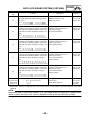
TIGHTENING TORQUES
CHASSIS TIGHTENING TORQUES
Part to be tightened
Thread
size
Tightening
torque
Remarks
Nm m·kg
Fuel tank and frame M6 10 1.0
Fuel tank and fuel tank bracket M8 15 1.5
Front wheel sensor and sensor housing M8 30 3.0 FJR1300A
Front brake pipe (hydraulic unit to front brake caliper) and
lower bracket
M6 7 0.7 FJR1300A
Front brake hose (hydraulic unit to front brake caliper)
holder and front wheel sensor lead holder on lower bracket
M6 7 0.7 FJR1300A
Front wheel sensor lead holder and lower bracket M6 7 0.7 FJR1300A
Front brake pipe union bolt M8 30 3.0 FJR1300A
Rear wheel sensor and sensor housing M8 30 3.0 FJR1300A
Rear wheel sensor lead holder and swingarm M5 4 0.4 FJR1300A
Rear brake hose (hydraulic unit to rear brake caliper) holder
and swingarm
M6 7 0.7 FJR1300A
Rear brake hose (rear brake master cylinder to hydraulic
unit) holder and frame
M6 7 0.7 FJR1300A
Rear brake hose (rear brake master cylinder to hydraulic
unit) holder
M6 7 0.7 FJR1300A
Rear wheel sensor lead holder M5 4 0.4 FJR1300A
Brake hose union bolt (hydraulic unit) M10 30 3.0 FJR1300A
Hydraulic unit and hydraulic unit bracket 1 M8 16 1.6 FJR1300A
Hydraulic unit bracket 1 and hydraulic unit bracket 2 M8 16 1.6 FJR1300A
Hydraulic unit bracket 2 and cross member M8 16 1.6 FJR1300A
Brake fluid reservoir cap M40 2 0.2
Reflector (for AUS only) M6 4 0.4
TIGHTENING TORQUES

– 11 –
SPEC
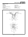
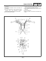
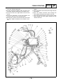
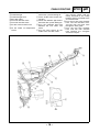
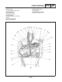
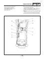
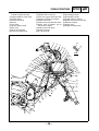
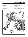
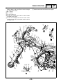
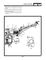
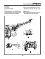
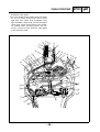
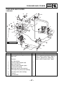
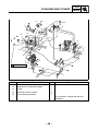
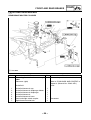
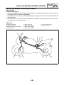
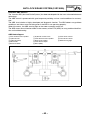
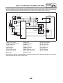
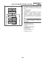
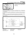
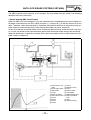
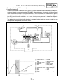
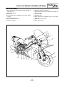
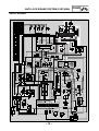
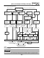
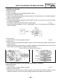
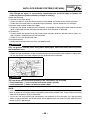
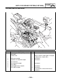
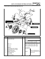
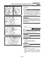
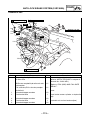
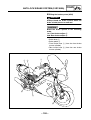
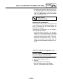
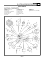
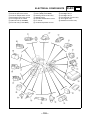
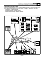
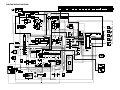
CABLE ROUTING
FJR1300
1 Throttle cable
2 Brake hose
3 Clutch hose
4 Main switch lead/immobilizer lead
5 Headlight lead
6 Fuse box
7 Thermostat assembly breather hose
8 Coolant reservoir hose
9 Hazard switch
0 Rectifier/regulator
A Plate
B Plunger control unit hose 2
C Radiator
D Radiator fan coupler
E Accessory box solenoid
CABLE ROUTING

– 12 –
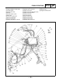
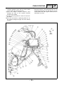
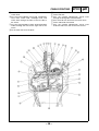
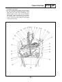
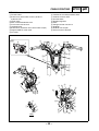
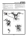
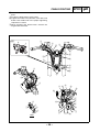
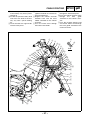
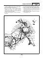
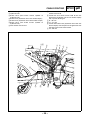
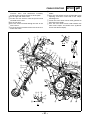
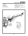
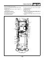
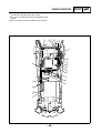
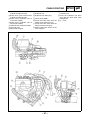
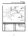
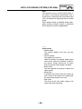
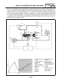
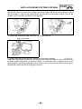
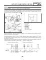
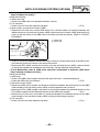
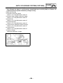
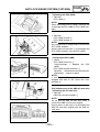
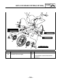
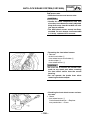
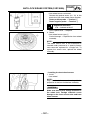
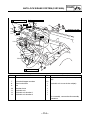
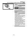
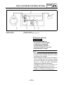
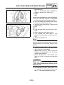
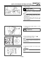
SPEC
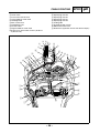
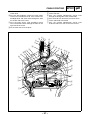
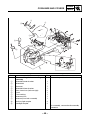
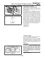
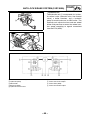
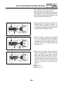
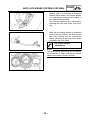
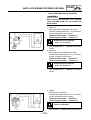
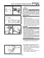
È Pass the right handlebar switch lead under the
handlebar.
É Pass the left handlebar switch lead under the
handlebar.
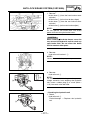
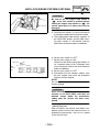
Ê Pass the wire harness, stator coil lead, coolant
reservoir hose, and thermostat assembly
breather hose through the left slit of the plate.
Ë To the thermostat housing
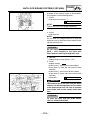
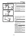
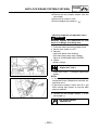
Ì After passing the coolant reservoir hose through
the two hose guides behind the plate, pass the
hose through the right hole of the plate.
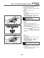
Í Pass plunger control unit hose 2 on the inside of
the plate.
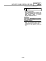
Î To the radiator fan
Ï Pass the radiator fan lead on the outside of the
plate.
CABLE ROUTING
La pagina si sta caricando...
La pagina si sta caricando...
La pagina si sta caricando...
La pagina si sta caricando...
La pagina si sta caricando...
La pagina si sta caricando...
La pagina si sta caricando...
La pagina si sta caricando...
La pagina si sta caricando...
La pagina si sta caricando...
La pagina si sta caricando...
La pagina si sta caricando...
La pagina si sta caricando...
La pagina si sta caricando...
La pagina si sta caricando...
La pagina si sta caricando...
La pagina si sta caricando...
La pagina si sta caricando...
La pagina si sta caricando...
La pagina si sta caricando...
La pagina si sta caricando...
La pagina si sta caricando...
La pagina si sta caricando...
La pagina si sta caricando...
La pagina si sta caricando...
La pagina si sta caricando...
La pagina si sta caricando...
La pagina si sta caricando...
La pagina si sta caricando...
La pagina si sta caricando...
La pagina si sta caricando...
La pagina si sta caricando...
La pagina si sta caricando...
La pagina si sta caricando...
La pagina si sta caricando...
La pagina si sta caricando...
La pagina si sta caricando...
La pagina si sta caricando...
La pagina si sta caricando...
La pagina si sta caricando...
La pagina si sta caricando...
La pagina si sta caricando...
La pagina si sta caricando...
La pagina si sta caricando...
La pagina si sta caricando...
La pagina si sta caricando...
La pagina si sta caricando...
La pagina si sta caricando...
La pagina si sta caricando...
La pagina si sta caricando...
La pagina si sta caricando...
La pagina si sta caricando...
La pagina si sta caricando...
La pagina si sta caricando...
La pagina si sta caricando...
La pagina si sta caricando...
La pagina si sta caricando...
La pagina si sta caricando...
La pagina si sta caricando...
La pagina si sta caricando...
La pagina si sta caricando...
La pagina si sta caricando...
La pagina si sta caricando...
La pagina si sta caricando...
La pagina si sta caricando...
La pagina si sta caricando...
La pagina si sta caricando...
La pagina si sta caricando...
La pagina si sta caricando...
La pagina si sta caricando...
La pagina si sta caricando...
La pagina si sta caricando...
La pagina si sta caricando...
La pagina si sta caricando...
La pagina si sta caricando...
La pagina si sta caricando...
La pagina si sta caricando...
La pagina si sta caricando...
La pagina si sta caricando...
La pagina si sta caricando...
La pagina si sta caricando...
La pagina si sta caricando...
La pagina si sta caricando...
La pagina si sta caricando...
La pagina si sta caricando...
La pagina si sta caricando...
La pagina si sta caricando...
La pagina si sta caricando...
La pagina si sta caricando...
La pagina si sta caricando...
La pagina si sta caricando...
La pagina si sta caricando...
La pagina si sta caricando...
La pagina si sta caricando...
La pagina si sta caricando...
La pagina si sta caricando...
La pagina si sta caricando...
La pagina si sta caricando...
La pagina si sta caricando...
La pagina si sta caricando...
La pagina si sta caricando...
La pagina si sta caricando...
La pagina si sta caricando...
La pagina si sta caricando...
La pagina si sta caricando...
La pagina si sta caricando...
La pagina si sta caricando...
La pagina si sta caricando...
La pagina si sta caricando...
La pagina si sta caricando...
La pagina si sta caricando...
La pagina si sta caricando...
La pagina si sta caricando...
La pagina si sta caricando...
La pagina si sta caricando...
La pagina si sta caricando...
La pagina si sta caricando...
La pagina si sta caricando...
La pagina si sta caricando...
La pagina si sta caricando...
La pagina si sta caricando...
La pagina si sta caricando...
La pagina si sta caricando...
La pagina si sta caricando...
La pagina si sta caricando...
La pagina si sta caricando...
La pagina si sta caricando...
La pagina si sta caricando...
La pagina si sta caricando...
La pagina si sta caricando...
La pagina si sta caricando...
La pagina si sta caricando...
La pagina si sta caricando...
La pagina si sta caricando...
La pagina si sta caricando...
La pagina si sta caricando...
La pagina si sta caricando...
La pagina si sta caricando...
La pagina si sta caricando...
La pagina si sta caricando...
La pagina si sta caricando...
La pagina si sta caricando...
-
 1
1
-
 2
2
-
 3
3
-
 4
4
-
 5
5
-
 6
6
-
 7
7
-
 8
8
-
 9
9
-
 10
10
-
 11
11
-
 12
12
-
 13
13
-
 14
14
-
 15
15
-
 16
16
-
 17
17
-
 18
18
-
 19
19
-
 20
20
-
 21
21
-
 22
22
-
 23
23
-
 24
24
-
 25
25
-
 26
26
-
 27
27
-
 28
28
-
 29
29
-
 30
30
-
 31
31
-
 32
32
-
 33
33
-
 34
34
-
 35
35
-
 36
36
-
 37
37
-
 38
38
-
 39
39
-
 40
40
-
 41
41
-
 42
42
-
 43
43
-
 44
44
-
 45
45
-
 46
46
-
 47
47
-
 48
48
-
 49
49
-
 50
50
-
 51
51
-
 52
52
-
 53
53
-
 54
54
-
 55
55
-
 56
56
-
 57
57
-
 58
58
-
 59
59
-
 60
60
-
 61
61
-
 62
62
-
 63
63
-
 64
64
-
 65
65
-
 66
66
-
 67
67
-
 68
68
-
 69
69
-
 70
70
-
 71
71
-
 72
72
-
 73
73
-
 74
74
-
 75
75
-
 76
76
-
 77
77
-
 78
78
-
 79
79
-
 80
80
-
 81
81
-
 82
82
-
 83
83
-
 84
84
-
 85
85
-
 86
86
-
 87
87
-
 88
88
-
 89
89
-
 90
90
-
 91
91
-
 92
92
-
 93
93
-
 94
94
-
 95
95
-
 96
96
-
 97
97
-
 98
98
-
 99
99
-
 100
100
-
 101
101
-
 102
102
-
 103
103
-
 104
104
-
 105
105
-
 106
106
-
 107
107
-
 108
108
-
 109
109
-
 110
110
-
 111
111
-
 112
112
-
 113
113
-
 114
114
-
 115
115
-
 116
116
-
 117
117
-
 118
118
-
 119
119
-
 120
120
-
 121
121
-
 122
122
-
 123
123
-
 124
124
-
 125
125
-
 126
126
-
 127
127
-
 128
128
-
 129
129
-
 130
130
-
 131
131
-
 132
132
-
 133
133
-
 134
134
-
 135
135
-
 136
136
-
 137
137
-
 138
138
-
 139
139
-
 140
140
-
 141
141
-
 142
142
-
 143
143
-
 144
144
-
 145
145
-
 146
146
-
 147
147
-
 148
148
-
 149
149
-
 150
150
-
 151
151
-
 152
152
-
 153
153
-
 154
154
-
 155
155
-
 156
156
-
 157
157
-
 158
158
-
 159
159
-
 160
160
-
 161
161
-
 162
162


Yamaha 2003 FJR1300 Manuale utente
- Categoria
- Motociclette
- Tipo
- Manuale utente
- Questo manuale è adatto anche per
in altre lingue
- English: Yamaha 2003 FJR1300 User manual
Documenti correlati
Altri documenti
-
Ducati ST3 2004 Workshop Manual
-
-
-
-
Aerpro CANHBRT1 Hi-Beam CAN-Bus Interface Guida d'installazione
-
 CAN CONNECT CANHBIZ1 Hi-Beam CAN-Bus Interface Manuale del proprietario
-
 Formula RX Istruzioni per l'uso
-
-
-
Philips TE50XX1 Manuale utente

