
1
BATTERY OPERATED HYDRAULIC CRIMPING TOOL
OUTIL HYDRAULIQUE DE SERTISSAGE SUR BATTERIE
HYDRAULISCHES AKKU-PRESSWERKZEUG
HERRAMIENTA HIDRÁULICA DE CRIMPADO A BATERÍA
UTENSILE OLEODINAMICO DA COMPRESSIONE A BATTERIA
B500ND B500NDA B500NDE B500NDT
ENGLISH
FRANÇAIS
DEUTSCH
ESPAÑOL
ITALIANO
ĞƌƟĮĞĚŶǀŝƌŽŶŵĞŶƚĂů
DĂŶĂŐĞŵĞŶƚ^LJƐƚĞŵ
ĞƌƟĮĞĚKĐĐƵƉĂƟŽŶĂů
,ĞĂůƚŚΘ^ĂĨĞƚLJ
DĂŶĂŐĞŵĞŶƚ^LJƐƚĞŵ
ĞƌƟĮĞĚYƵĂůŝƚLJ
DĂŶĂŐĞŵĞŶƚ^LJƐƚĞŵ
OPERATION AND MAINTENANCE MANUAL ....................................5
NOTICE D’UTILISATION ET ENTRETIEN ........................................... 13
BEDIENUNGSANLEITUNG ................................................................... 21
MANUAL DE USO Y MANTENIMIENTO ........................................... 29
MANUALE D’USO E MANUTENZIONE ............................................. 37
18 M 051

2
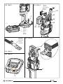
FIG. / BILD 1 FIG. / BILD 2
FIG. / BILD 3
FIG. / BILD 4
FIG. / BILD 5
3
49
Connector
Connecteur
Kabelschuh
Conector
Connettore
Battery
Batterie
Akku
Batería
Batteria
62
42
Die set
Matrices
Presseinsätze
Matrices
Matrici
83
62
9
P
6
41

3
1
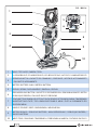
HEAD / TETE / KOPF / CABEZA / TESTA
2
4 LED WORKLIGHT / ECLAIRAGE PAR LED / LED-BELEUCHTUNG / LUCES LED / ILLUMINAZIONE LED
3
OPERATING BUTTON / GACHETTE DE COMMANDE / STARTKNOPF / BOTÓN DE ACCIONAMIENTO
/ PULSANTE DI AZIONAMENTO
4
BATTERY / BATTERIE / AKKU / BATERÍA / BATTERIA
5
DISPLAY / ECRAN / DISPLAYANZEIGE / PANTALLA / DISPLAY
6
PRESSURE RELEASE BUTTON / GACHETTE DE DECOMPRESSION / DRUCKABLASSKNOPF / BOTÓN
DESBLOQUEO PRESIÓN / PULSANTE SBLOCCO PRESSIONE
7
TOUCH BUTTON FOR MENU SELECTION / TOUCHE POUR SELECTIONNER LE MENU / TRAGERIEMEN
KAPAZITIVE TOUCH TASTE / TECLA PARA SELECCIONAR EL MENÚ / TASTO A SFIORAMENTO PER
SELEZIONE MENU
8
HANDLE / POIGNEE / GRIFF / EMPUÑADURA / IMPUGNATURA
9
BATTERY RELEASE / DEBLOCAGE BATTERIE / AKKU ENTRIEGELUNG / DESBLOQUEO BATERÍA /
SBLOCCO BATTERIA
10
WRIST STRAP / DRAGONNE / TRAGERIEMEN / CORREA PARA LA MUÑECA / CINTURINO DA POLSO
FIG. / BILD 6
3
4
10
9
8
2
1
5
7
6

4
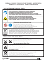
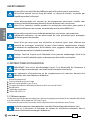
– Before using the tool, carefully read the instructions in this manual.
– Avant d'utiliser cet outil, lire attentivement les instructions de cette notice.
– Vor Inbetriebnahme unbedingt die Bedienungsanleitung durchlesen.
– Antes de utilizar la herramienta, leer atentamente las instrucciones en este manual.
– Prima di utilizzare l'utensile, leggere attentamente le istruzioni riportate in questo manuale.
– When operating the tool, keep hands away from the danger zone.
– Au cours du sertissage, tenir les mains éloignées de la zone de travail.
– Während des Verpressens nicht mit den Händen in den Pressbereich gelangen.
– Durante su utilización, mantenga las manos fuera de la zona de peligro.
– Durante l'utilizzo, mantenere le mani fuori dalla zona di pericolo.
– Always close the tool head correctly and securely.
– S'assurer toujours de la parfaite fermeture de la tête.
– Immer darauf achten, dass der Kopf richtig verriegelt ist.
– Asegurarse siempre de que la cabeza está correctamente cerrada.
– Assicurarsi sempre della perfetta chiusura della testa.
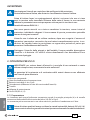
WARNING SYMBOLS - SYMBOLES D'AVERTISSEMENT - WARNSYMBOLE -
SÍMBOLOS DE ADVERTENCIA - SIMBOLI DI AVVERTENZA
– Never throw batteries into fi re or water.
– Jamais jeter les batteries dans le feu ou dans l'eau.
– Werfen Sie Akkus nicht ins Feuer oder Wasser.
– Nunca tire las baterías al fuego o al agua
– Mai gettare le batterie nel fuoco o in acqua.
– Always recycle the batteries.
– Recycler toujours les batteries.
– Verbrauchte Akkus stets dem Recycling zuführen.
– Reutilizar siempre las baterías.
– Riciclare sempre le batterie.
– Do not discard batteries into domestic refuse or waste disposal.
– Ne pas jeter de batteries dans une poubelle ou autre lieu non prévu à cet eff et.
– Verbrauchte Akkus nicht der allgemeinen Abfallentsorgung zuführen.
– No tirar las baterías al cubo de basura o lugar parecido.
– Non buttate le batterie fuori uso nei cestini della spazzatura o luoghi simili.
– User information (Directives 2011/65/EU and 2012/19/EU), see page 46.
– Information pour les utilisateurs (Directives 2011/65/EU et 2012/19/EU) voir page 46.
– Information für den Benutzer (Richtlinien 2011/65/EU und 2012/19/EU) siehe Seite 46.
– Informe para los usuarios (Directivas 2011/65/EU y 2012/19/EU) vease página 46.
– Informazione agli utenti (Direttive 2011/65/EU e 2012/19/EU) vedere pagina 46.
Battery - Batterie - Akku - Batería - Batteria
Tool - Outil - Werkzeug - Herramienta - Utensile

5
(1)
Directive 2006/42/EC, annexe 1, point 1.7.4.2 letter u
L
pA
= weighted continuous acoustic pressure level equivalent.
L
pCPeak
= maximum value of the weighted acoustic displacement pressure at the work place.
L
WA
= acoustic power level emitted by the machine.
(2)
Directive 2006/42/EC, annexe 1, point 2.2.1.1
Weighted root mean square in frequency of the acceleration the upper limbs are exposed to for each biodynamic
reference axis. Tests carried out in compliance with the indications contained in EN ISO 5349-1/2 Standard, and under
operating conditions much more severe than those normally found.
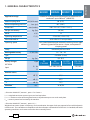
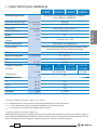
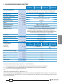
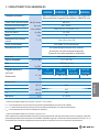
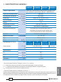
1. GENERAL CHARACTERISTICS
ENGLISH
B500ND B500NDE B500NDT B500NDA
Application range suitable for installing electrical compression connectors on
conductors up to 300 mm
2
(600 MCM)
Rated crimping force
kN (US sh. ton)
60 (6.75)
Minimum operating pressure
bar (psi) 661 (9587)
Dimensions mm (inches) 396 x 135 x 81 (15.6 x 5.3 x 3.2)
Weight with battery kg (lbs) 3,0 (6.6)
Motor V DC 18
Operating temperature °C (°F) -15 to +50 (+5 to +122)
Recommended oil AGIP ARNICA 32 or equivalents
Operating speed twin speed operation and automatic switching from a rapid
advancing speed of the ram to a slower, more powerful
crimping speed
Safety maximum pressure valve
Rechargeable battery V / Ah / Wh 18 / 2.0 / 36
Type CB1820L (Li-Ion)
Weight kg (lbs) 0,4 (0.9)
Battery charger
ASC30-36
Input
type
EU
27044000
UK
27045000
AUS/NZ
27047000
USA/CAN
27046000
V / Hz 220 - 240 / 50 - 60 115 / 60
W85
Acoustic noise
(1)
L
pA
dB (A)
67,7
L
pCPeak
dB (C) 89,2
L
WA
dB (A) 74,2
Vibration
(2)
m/s
2
a
hv
0,724

6
ENGLISH
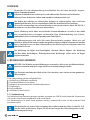
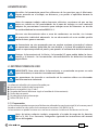
WARNING
Do not use the tool for purposes other than those intended by Cembre.
The operator should concentrate on the work being performed and be careful to
maintain a balanced working position.
Before starting work on electrical equipment, please ensure that either there are
no live parts in the immediate working area or that precautions are taken for
working near live parts in accordance with EN50110-1.
Do not use this tool on or near live conductors without proper personal
protective equipment. Failure to observe this warning could result in severe injury
or death.
The tool is unsuitable for continuous use and should be allowed to cool down fol-
lowing uninterrupted, successive crimping operations. For example, having ex-
hausted a fully charged battery in one session, delay battery replacement for a
few minutes.
Protect the tool from rain and moisture. Water will damage the tool and battery.
Electro-hydraulic tools should not be operated in pouring rain.
2. INSTRUCTIONS FOR USE
IMPORTANT: In order to avoid damaging the tool, do not operate at maximum
pressure, without dies inserted in the head.
When introducing or changing dies, the battery must fi rst be removed from the tool.
The part reference includes the following:
Hydraulic crimping tool.
Li-Ion rechargeable battery (2 pcs).
Battery charger (model depends on the tool version).
Shoulder strap.
Plastic carrying case.
USB cable (Ref. to section 5).
2.1) Preparation
The tool can be easily carried using either the main handle (8) or the shoulder strap attached to the
two eyelets of the wrist strap (10) (Ref. to FIG. 6).
The tool can be held in one hand while positioning the conductor with the other.
Before starting any work, check the battery charge (Ref. to section 2.8) and recharge if
necessary, following the instructions in the battery charger user manual.

7
ENGLISH
terminal
connector
1
2
3
1
2
1
3
2
3
conductor
conductor
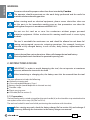
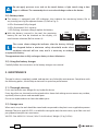
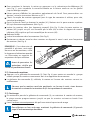
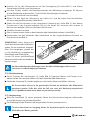
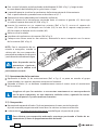
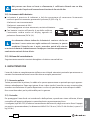
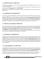
To replace the battery, remove it by pressing the release button (9) (Ref. to Fig. 1), then
insert the new battery, sliding it into the guides until it locks.
The display shows the operational parameters of the tool; to customise, proceed
as described in section 2.7.
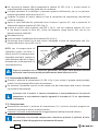
Select the appropriate die set for the connector.
Open the latch (41) and release the upper die holder (42) (Ref. to Fig. 2).
Insert one die into the upper die holder (42) until locked by the ball (83) and one die
into the lower die support (49) until locked by the spring clips (62) (Ref. to Fig. 2).
Close the head.
Insert the conductor into the connector (Ref. to Fig. 3).
Position the connector between the dies and ensure the correct location of the crimp
(Ref. to Fig. 4).
NOTE: when more than one
compression is required, proceed
according to the sequence and
direction indicated in the fi gure
opposite.
Ensure that the latch and the upper die holder are fully secured, otherwise damage
may occur during tool operation.
2.2) Die advancement
Press operating button (3) (Ref. to Fig. 4) to activate the motor-pump and advance the
lower die.
To halt the advancement, release operating button (4) and the motor will cut out.
Make sure the dies are exactly positioned on the desired crimp point otherwise
re-open dies following instructions as per section 2.4 and reposition the connector.
2.3) Compression
By keeping the operating button (3) pressed, the motor continues to operate and the ram will
gradually move forward until the two dies touch.
The motor will stop automatically when the set pressure has been reached.
To perform a full compression, press and hold the operating button (3) until the
motor stops automatically.

8
ENGLISH
ERROR
Ï
Ð
Fm = 60.0 kN
F
p = 58.3 kN
Pm = 661 bar
P
p= 485 bar
Fm = 60.0 kN
OK
Pm = 661 bar
OK
3 SEC.
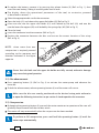
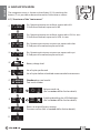
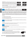
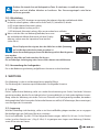
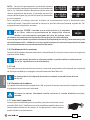
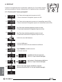
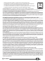
NOTE: To display the momentary force or pressure during
the work cycle, select the appropriate display from the
menu (Ref. to section 4). When the operating button is
released before the motor stops automatically, the display
will show the peak force (Fp) or the peak pressure (Pp)
reached at that point.
To complete the cycle, press the operating button again until the motor stops automatically; the display
will show the maximum force or pressure reached followed by "OK" to confi rm correct operation.
The display "ERROR", combined with a beep and the LEDs flashing,
indicates an incorrect crimping procedure caused by the work
cycle being interrupted before the control parameters (force/
pressure) of the tool are reached.
This error appears when the pressure release button has been operated and the tool has
already reached a pressure >100 bar. In this case, repeat the compression by pressing and
holding the operating button until the motor stops automatically.
2.4) Release of dies
Once the motor has stopped automatically, release the operating button (3), the ram will return,
allowing access and release of the dies.
The oil discharge to reservoir can also be performed in manual mode (Refer to § 4.2 for
further details).
2.5) LED Worklights
Whilst the tool is in operation, the compression area is illuminated by four high luminosity LED
Worklights that switch off automatically at the end of the cycle.
The LED Worklights can be disabled by following the procedure described in section 4.3.
2.6) Head rotation
For ease of operation, the tool head can rotate through 180°, allowing the operator to
work in the most comfortable position.
Do not attempt to rotate the head when the hydraulic circuit is pressurised.
2.7) Capacitive touch button for menu selection
This button is located under the display and allows selection of
various screens (Ref. to section 4); accessible only when the display is on.
Wearing gloves or using other objects may inhibit the operation of the
button, therefore use a bare fi nger to apply only a light touch.

9
ENGLISH
BATTERY
Ï
Ð
max.
BATTERY BATTERY
Ï
Ð
min.
Do not apply pressure to or stab at the touch button, a light touch using a bare
fi nger is suffi cient. The command pulse is sent when the fi nger releases the button.
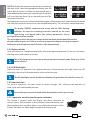
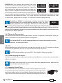
2.8) Battery status
The battery is equipped with LED indicators that indicate the remaining battery life at
any time by pressing the adjacent button (P) (Ref. to Fig. 5):
4 LEDs illuminated: fully charged
2 LEDs illuminated: 50 % capacity
1 LED flashing: minimum charge, replace the battery
With the battery inserted in the tool, the remaining
battery life can also be checked on the display, via
touch button selection (Ref. to section 4).
The screen shown alongside indicates that the battery Voltage
has dropped below a minimum safety threshold; under these
conditions the tool will not start, and it is necessary to recharge
or replace the battery.
The approximate time to fully recharge a battery is about 40 minutes.
2.9) Using the battery charger
Carefully follow the instructions in the battery charger user manual.
3. MAINTENANCE
The tool is robust, completely sealed, and requires very little daily maintenance. Compliance with
the following points, should help to maintain its optimum performance:
3.1) Thorough cleaning
Dust, sand and dirt are a danger for any hydraulic device.
Every day, after use, the tool must be wiped with a clean cloth taking care to remove any residue,
especially close to pivots and moveable parts.
Do not use hydrocarbons to clean the rubber parts.
3.2) Storage case
When not in use, the tool should be stored and transported in the plastic case supplied to prevent
damage. The case, type VAL-P22, is suitable for storing the tool, the accessories, up to 9 die sets and
pre-prepared compression connectors.
VAL P22: Size 465x315x116 mm (18.3x12.4x4.6 inches). Weight 1,5 kg (3.3 lbs).

10
ENGLISH
B500ND
NR 18AW125
10
29990
3
BATTERY
RESET
SW:S1J96900
Pm = 661 bar
P
= 0 bar
Pm = 9587 psi
LED
ON
LED
OFF
* 1
* 2
* 3
* 4
* 5
* 6
* 7
8
9
10
11
P = 0 psi
Fm = 60.0 kN
F = 0.0 kN
Fm = 6.75 ton
F = 0.00 ton
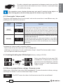
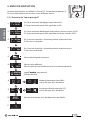
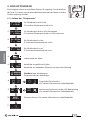
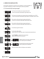
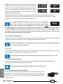
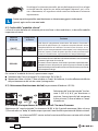
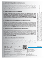
4. NAVIGATION MENU
The navigation menu is shown on the display (5). By touching the
button (7) it is possible to browse the menu via the various screens.
4.1) Structure of the "main menu"
Fm: Operating/minimum set force, expressed in kN.
F: Peak force reached, expressed in kN.
Fm: Operating/minimum set force, expressed in USA sh. tons.
F: Peak force reached, expressed in USA sh. tons.
Pm: Operating/minimum set pressure, expressed in bar.
P: Peak pressure reached, expressed in bar.
Pm: Operating/minimum set pressure, expressed in psi.
P: Peak pressure reached, expressed in psi.
Battery charge level
No. of cycles performed.
No. of cycles before scheduled recommended maintenance.
Cembre logo, tool model.
Tool serial number
Release mode set
(Ref. to section 4.2 for further details).
Enabling/disabling the LED Worklights.
(Ref. to section 4.3 for further details).
Return to original factory settings.
Firmware version (Ref. to section 4.4 for further details).
7
5

11
ENGLISH
3 SEC.
To make a selected screen operational and appear at each start up of the
tool, operate the touch button for at least 3 seconds; a continuous beep
will confi rm the setting.
The capacitive menu selection button may not work if touched using objects or
when wearing gloves, therefore always operate the button using a bare fi nger.
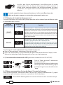
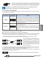
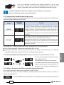
4.2) Choosing the "release mode"
The phase of discharging the oil into the tool’s tank can be carried out in two diff erent ways, de-
pending on the mode set in the menu:
Release
mode
Associated
pictogram
Function
SMART
factory setting
By releasing the operating button (3) the oil is returned in full to
the tool reservoir only following automatic shut-off of the motor.
During the return phase, pressing the buttons enables the ram
stroke to be interrupted at any point so as to be able to restart from
this position in the next work phase, thus saving time and energy.
MANUAL
To return the oil to the tool reservoir it is necessary to press and
hold the release button (6).
During the return phase, by releasing the button it is possible for
the ram stroke to be interrupted at any point so as to be able to
restart from this position in the next work phase, thus saving time
and energy.
To change the "release mode", proceed as follows:
- Select screen 8 from the “main menu” (Ref. to section 4.1).
- Hold finger on the button (7) until a confirmation “beep” is heard. The choice made is shown
by cursor position under the pictogram.
4.3) Enabling/disabling the LED Worklights (factory setting is LED ON)
Select screen 9 from the “main menu” (Ref.
to section 4.1). To deactivate or reactivate
operation of the LED Worklights, hold the
finger on button (7) until a confirmation
“beep” is heard.
4.4) Return to original factory settings / fi rmware version
Select screen 10 from the “main menu” (Ref. to section 4.1). To return the tool to its factory settings,
hold finger on button (7) until a confirmation “beep” is heard.
The RESET screen also shows the fi rmware version of the control board.
LED
OFF
LED
ON
LED
OFF
LED
ON
BEEP
2
RESET
SW:S1J96900

12
ENGLISH
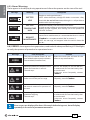
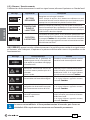
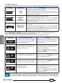
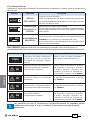
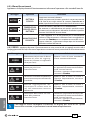
4.5) Alarms/Warnings
These appear on the display during operation and inform the operator on the state of the tool.
Message Meaning Description
BATTERY
Ï
Ð
BATTERY
LOW
Replace or recharge the battery.
NOTE: when the battery voltage falls below a minimum safety
threshold, the tool will not start, although it is still possible to
end the work cycle in progress.
BATTERY
Ï
Ð
BATTERY
TEMPERATURE
HIGH
Remove the battery and wait until it cools down.
In order to cool quicker, it is possible to insert it into the supplied
battery charger supplied, thus making use of the specifi c “AIR
COOLED” function.
30001
3
Ð
REQUEST
MAINTENANCE
No. of cycles to recommended maintenance is reached. The tool
continues to work however, it is recommended that it is sent to
Cembre for a complete overhaul (Ref. to section 7).
NOTE: this message, will reappear when the tool has been idle
for 30 s.
4.6) ERRORS: these appear during operation, combined with a beep and fl ashing LED Worklights,
to notify the operator of procedural or operational errors.
Message Error description Solution
ERROR
Ï
Ð
The pressure release button (6) was
pressed before the control parameters
were reached (Force/Pressure).
Repeat the work cycle and wait for the
motor to stop automatically.
001
Ï
Ð
Abnormal power consumption of the
motor for more than 3 seconds.
The tool stops.
Wait for the display to turn off (60 sec.)
or remove and re-insert the battery, then
re-start the tool.
If the error occurs frequently, contact
Cembre.
002
Ï
Ð
Output voltage of the pressure trans-
mitter is out of the pre-set range.
Repeat the work cycle; if the error occurs
frequently, contact Cembre.
003
Ï
Ð
Failure to reach the set pressure within
30 seconds continuous operation of
the tool.
Repeat the work cycle; if the error occurs
frequently, contact Cembre.
004
Ï
Ð
Overcharging of the battery with
protection tripping.
The tool stops.
Wait for the display to turn off (60 sec.)
or remove and re-insert the battery, then
re-start the tool.
If the error occurs frequently, contact
Cembre.
Error screens are displayed for about 30 seconds before being reset, but will display
repeatedly in the event of permanent anomalies.

13
1. CARACTERISTIQUES GENERALES
B500ND B500NDE B500NDT B500NDA
Domaine d'application: conçu pour le sertissage des connecteurs électriques
jusqu' à 300 mm
2
(600 MCM)
Force nom. de sertissage
kN (US sh. ton)
60 (6.75)
Pression min. de travail bar (psi) 661 (9587)
Dimensions mm (inches) 396 x 135 x 81 (15.6 x 5.3 x 3.2)
Poids avec batterie kg (lbs) 3,0 (6.6)
Moteur V DC 18
Température de fonction-
nement:
°C (°F) -15 à +50 (+5 à +122)
Huile recommandée: AGIP ARNICA 32 ou équivalents
Avance rapide:
l’outil passe automatiquement de la vitesse rapide d’appro-
che des matrices à la vitesse lente de sertissage
Sécurité valve de surpression
Batterie rechargeable V / Ah / Wh 18 / 2.0 / 72
Type CB1820L (LI-Ion)
Poids kg (lbs) 0,4 (0.9)
Chargeur de batterie
ASC30-36
Alimentation
type
EU
27044000
UK
27045000
AUS/NZ
27047000
USA/CAN
27046000
V / Hz 220 - 240 / 50 - 60 115 / 60
W85
Bruit aérien sonore
(1)
L
pA
dB (A) 67,7
L
pCPeak
dB (C) 89,2
L
WA
dB (A) 74,2
Vibrations
(2)
m/s
2
a
hv
0,724
FRANÇAIS
(1)
Directive 2006/42/CE, annexe 1, point 1.7.4.2, lettre u
L
pA
= niveau de pression sonore continue équivalente pondérée A sur le poste de travail.
L
pCPeak
= valeur de pression sonore instantanée pondérée C sur le poste de travail.
L
WA
= niveau de puissance acoustique dégagée par la machine.
(2)
Directive 2006/42/CE, annexe 1, point 2.2.1.1
Valeur quadratique moyenne pondérée en fréquence de l'accélération à laquelle sont exposés les membres supérieurs
pour chaque axe biodynamique de référence. Relevés réalisés suivant les indications de la Norme EN ISO 5349-1/2,
dans des conditions de service largement représentatives des conditions d'emploi normales.

14
FRANÇAIS
AVERTISSEMENT
Ne pas utiliser cet outil à des fi ns diff érentes que celles prévues par le constructeur.
Restez bien attentif tout au long du travail, ne soyez pas distrait, ne perdez pas
l’équilibre pendant l'utilisation.
Avant d’entreprendre des travaux sur des équipements électriques, veuillez vous
assurer qu’aucun élément aux abords de la zone de travail n’est sous tension.
Dans le cas contraire, veuillez prendre les précautions nécessaires pour opérer à
proximité d’éléments sous tension, en conformité avec la norme EN50110-1.
Ne pas utiliser cet outil sur ou à côté de conducteurs sous tension, sans protection
individuelle adéquate. La non observation de cette précaution peut provoquer
des lesions graves ou mortelles.
L’outil n’est pas conçu pour une utilisation en continu; après avoir effectué une
quantité de sertissages consécutifs à partir d’une batterie complètement chargée,
au moment du remplacement de la batterie, nous suggérons d'observer une période
d’arrêt pour permettre le refroidissement de l’outil.
Protéger l’outil de la pluie et de l’humidité. L’eau pourrait endommager l’outil et la
batterie, les outils hydroélectriques ne devraient pas être utilisés sous la pluie
.
2. INSTRUCTIONS D'UTILISATION
IMPORTANT: Pour éviter d’endommager l’outil, il est déconseillé de l’actionner à
vide et à la pression maximale, sans avoir inséré les matrices dans la tête.
Les opérations d’introduction ou de remplacement des matrices doivent être
eff ectuées avec l’outil dépourvu de batterie.
L' ensemble comprend:
Outil hydraulique de sertissage.
Batterie rechargeable Li-Ion (2 pcs).
Chargeur de batterie (diff érent en fonction de la version de l'outil).
Bandoulière.
Coff ret de rangement.
Câble USB (Voir § 5).
2.1) Mise en service
L'outil peut être facilement transporté en utilisant la poignée principale (8) ou la bandoulière fi xée
aux deux oeillets de la dragonne (10) (Voir Fig. 6).
L'outil peut être tenu dans une main tout en positionnant le conducteur avec l'autre.
Avant de commencer toute opération, contrôler l’état de charge de la batterie (voir
§ 2.8) et, si nécessaire, la recharger en suivant les instructions contenues dans le
manuel d’utilisation du chargeur de batteries.

15
FRANÇAIS
Pour remplacer la batterie, la retirer en appuyant sur le mécanisme de déblocage (9)
(voir Fig. 1), puis introduire la nouvelle batterie en la faisant coulisser sur les guides
jusqu’au blocage complet.
L’écran permet d’affi cher les paramètres opérationnels de l’outil. Pour personnaliser ces
derniers, suivre les instructions décrites au § 2.7.
Choisir le couple de matrices approprié pour le type de connexion à réaliser; pour cela,
consulter le catalogue.
Ouvrir la tête de l'outil en écartant le crochet (41), libérant ainsi le porte matrice supérieur
(42) qui s'écartera complètement (Voir Fig. 2).
Insérer les matrices dans leur logement respectif (Voir Fig. 2) dans le porte matrice su-
périeur (42) jusqu'à ce qu'il soit verrouillé par la bille (83) et dans le support de matrice
inférieure (49) jusqu'à ce qu'il soit verrouillé par les ressorts (62).
Refermer la tête.
Insérer le conducteur dans le connecteur (Voir Fig. 3).
Positionner ce dernier entre les deux matrices en alignant la zone à sertir avec l'empreinte
des matrices (Voir Fig. 4).
REMARQUE: s’il est nécessaire de
procéder à plusieurs sertissages
de cosses ou de manchons, suivre
la séquence et la direction reportée
sur l’illustration en espaçant les
empreintes de façon uniforme.
Avant de poursuivre les
opérations, vérifier que
la tête soit parfaitement fermée.
2.2) Avance des matrices
Appuyer sur la gâchette de commande (3) (Voir Fig. 4) pour mettre en marche le groupe
moteur pompe; les matrices commencent alors à se rapprocher du connecteur.
La gâchette de commande (3) relâchée, le moteur et l'avance des matrices cessent im-
médiatement.
S
S'assurer que les matrices sont bien positionées sur la zone à sertir, sinon desserer
les matrices en suivant les instructions du § 2.4 et repositioner le connecteur.
2.3) Sertissage
En maintenant pressée la gâchette de commande (3), on maintient la rotation du moteur;
le piston avance progressivement jusqu'à ce que les matrices arrivent en butée l'une
contre l'autre.
L’outil s’arrêtera automatiquement dès qu’il aura atteint la pression de tarage.
Pour effectuer un bon sertissage, maintenir la gâchette de commande (3) pressée
jusqu’à l’arrêt automatique du moteur.
cosse
manchon
1
2
3
1
2
1
3
2
3
conducteur
conducteur

16
FRANÇAIS
ERROR
Ï
Ð
Fm = 60.0 kN
F
p = 58.3 kN
Pm = 661 bar
P
p= 485 bar
Fm = 60.0 kN
OK
Pm = 661 bar
OK
3 SEC.
REMARQUE: Pour affi cher la force ou la pression en temps
réel, lors du cycle de travail, confi gurer les écrans corres-
pondants (voir § 4). En relâchant le bouton de démarrage
avant l’arrêt automatique du moteur, l’écran affi chera
les valeurs de pic de la force (Fp) et de la pression (Pp)
atteintes à ce moment.
Pour terminer l’opération, ré-appuyer sur la gâchette de commande jusqu’à l’arrêt automatique
du moteur; l’écran affi chera la force ou la pression maximale atteinte, suivie de l’inscription "OK"
indiquant que l’opération a été correctement eff ectuée.
Le message "ERROR" associé à l’avertisseur sonore ainsi que le
clignotement des LED indiquent que la procédure de sertissage
n’a pas été correctement effectuée en raison d’un arrêt anticipé
du cyclede travail avant d’avoir atteint les paramètres réglés (force/pression) de l’outil. Ce message
d’erreur s’affi che lorsque l’opérateur appuie sur la gâchette de déblocage pression après que l’outil
ait atteint une pression > 100 bar. Dans ce cas, eff ectuer à nouveau le sertissage en maintenant la
gâchette de commande appuyée jusqu’à l’arrêt automatique du moteur. Pour terminer l’opération,
ré-appuyer sur la gâchette de commande jusqu’à l’arrêt automatique du moteur; l’écran affi chera la
force ou la pression maximale atteinte, suivie de "OK" indiquant que l’opération a été correctement
eff ectuée.
2.4) Réouverture des matrices
Après l'arrêt automatique du moteur, relâcher le bouton d'actionnement (3), le piston revient, avec
l'ouverture conséquente des matrices.
La phase de vidange d'huile dans le réservoir peut également être eff ectuée manuellement
(voir § 4.2 pour plus de détails)
2.5) Led
Lors de l’actionnement de l’outil, la zone de sertissage est éclairée au moyen de quatre LED haute
luminosité qui s’éteignent automatiquement à la fi n du cycle.
Pour désactiver les LED, suivre la procédure décrite au § 4.3.
2.6) Rotation de la tête
La tête de l'outil pivote de 180° par rapport au corps, permettant à l'utilisateur de travailler dans la
meilleure position.
Ne pas forcer la rotation de la tête, lorsque le circuit hydraulique est sous pression.
2.7) Touche tactile de type capacitif
Cette touche est située sous l’écran et permet de sélectionner les diff érents
écrans (voir § 4); elle fonctionne uniquement lorsque l’écran est allumé
et il suffi t de l’effl eurer à mains nues. L’utilisation de gants ou d’autres
objets risquerait de compromettre son activation.

17
FRANÇAIS
BATTERY
Ï
Ð
max.
BATTERY BATTERY
Ï
Ð
min.
Ne jamais appuyer avec force sur la touche tactile, il suffit de l’effleurer avec un
doigt, à mains nues. La commande envoie l’impulsion dès le retrait du doigt.
2.8) Autonomie de la batterie
La batterie est équipée d’indicateurs à LED qui permettent de contrôler, à tout moment,
son autonomie résiduelle en appuyant sur la touche (P) (voir Fig. 5):
4 led allumées: autonomie maximale
2 led allumées: autonomie à 50 %
1 led clignotante: autonomie minimale, remplacer la batterie
Lorsque la batterie est insérée dans l’outil, il est possible
de vérifi er l’autonomie résiduelle à partir de l’écran,
en appuyant sur la touche tactile (voir § 4).
L’écran ci-contre indique que la batterie est déchargée et que sa
tension est descendue au-dessous du seuil minimal de sécurité;
dans cette situation, l’outil ne démarre pas, il est donc nécessaire de
recharger ou de remplacer la batterie.
À titre indicatif, le délai de recharge complète de la batterie correspond à environ 40 min.
2.9) Utilisation du chargeur de batterie
Suivre attentivement les instructions indiquées sur le manuel.
3. ENTRETIEN
L'outil est robuste, complètement scellé et ne nécessite aucune préoccupation ou attention parti-
culière. Les recommandations qui suivent sont néanmoins souhaitables pour assurer une longévité
optimum:
3.1) Nettoyage élémentaire
Veiller à protéger l'outil de la poussière, du sable et de la boue qui sont un danger à tout système
hydraulique. Chaque jour après utilisation, l'outil doit être nettoyé à l'aide d'un chiff on propre, tout
particulièrement aux endroits de pièces mobiles.
Ne jamais utiliser d’hydrocarbures pour le nettoyage des parties en caoutchouc.
3.2) Rangement
Au repos, pour protéger l'outil des coups accidentels et de la poussière, il convient de le ranger
dans le coff ret. Ce coff ret (type VAL-P22), adapté pour contenir l'outil, ses accessoires et 9 paires de
matrices a comme dimensions: 465x315x116 mm (18.3x12.4x4.6 inches) et un poids de 1,5 kg (3.3 lbs).

18
FRANÇAIS
B500ND
NR 18AW125
10
29990
3
BATTERY
RESET
SW:S1J96900
Pm = 661 bar
P
= 0 bar
Pm = 9587 psi
LED
ON
LED
OFF
* 1
* 2
* 3
* 4
* 5
* 6
* 7
8
9
10
11
P = 0 psi
Fm = 60.0 kN
F = 0.0 kN
Fm = 6.75 ton
F = 0.00 ton
4. MENU DE NAVIGATION
Le menu de navigation est affi ché sur l'écran (5). En touchant le bouton (7)
il est possible de parcourir le menu via les diff érents écrans.
4.1) Structure du "menu principal"
Fm: Force minimale de réglage, exprimée en kN.
F: Force atteinte en temps réel, exprimée en kN.
Fm: Force minimale développée, exprimée en tonnes courtes (USA).
F: Force atteinte en temps réel, exprimée en tonnes courtes (USA).
Pm: Pression nominale / minimale garantie, exprimée en bar.
P: Pression instantanée.
Pm: Pression nominale / minimale garantie, exprimée en psi.
P: Pression instantanée.
Niveau de charge de la batterie
Nbr de cycles eff ectués.
Nbr de cycles restant à eff ectuer avant l'entretien préconisé.
Logo Cembre, type de outil.
Numéro de série.
Mode de décompression défi ni.
(voir § 4.2 pour plus de détails).
Activation/désactivation des LED
(voir § 4.3 pour plus de détails).
Version du fi rmware. (voir § 4.4 pour plus de détails).
7
5

19
FRANÇAIS
3 SEC.
Une fois que l’écran présélectionné s’est affiché, pour le rendre
opérationnel et fixe à chaque démarrage de l’outil, maintenir la
touche tactile appuyée pendant une période prolongée (au moins
3 secondes). Un signal sonore continu confirmera la configuration
eff ective.
La touche capacitive risque de ne pas fonctionner si celle-ci est effl eurée avec des
objets ou des gants, appuyer sur cette touche uniquement à mains nues.
4.2) Sélection du "mode de décompression"
Le retour d'huile dans le réservoir de la pompe peut être réalisé de deux façons diff érentes selon
le mode défi ni dans le menu:
Mode de
décompression
Pictogramme
associé
Fonction
SMART
Réglage d’usine
Seulement après un arrêt automatique du moteur, en relâchant le
bouton (3) de mise en marche on assiste automatiquement au retour
complet de l'huile dans le réservoir de l'outil. Au cours de la phase
de retour, une impulsion sur les boutons permet d'interrompre la
course du piston à tout moment afi n de recommencer à partir de
cette position la prochaine phase de travail, économisant ainsi du
temps et de l'énergie.
MANUAL
Pour obtenir le retour de l'huile dans le réservoir de l'outil il faut
maintenir appuyé le bouton (6) de décompression.
Au cours de la phase de retour, en relâchant le bouton, il est à tout
moment possible d'interrompre la course du piston afi n de recom-
mencer à partir de cette position la prochaine phase de travail
économisant ainsi du temps et de l'énergie.
Pour changer le "mode de décompression", procéder comme suit:
Dans le "Menu principal", sélectionner l'écran 8 (voir § 4.1).
Presser le touche tactile (7) jusqu'à entendre le signal sonore de confi rmation "beep", le choix
eff ectué est indiqué par le positionnement du curseur sous le pictogramme.
4.3) Activation/désactivation des LED (paramètre standard d’usine: LED ACTIVÉE)
Dans le "Menu principal", sélectionner
l'écran 9 (voir § 4.1).
Pour le désactiver ou réactiver le démarrage
des LED, presser le touche tactile (7) jusqu'à
entendre le signal sonore de confi rmation
"beep".
4.4) Retour au paramètres d’usine de départ / Version du fi rmware
Dans le "Menu principal", sélectionner l'écran 10 (voir § 4.1), presser le touche tactile (7) jusqu'à
entendre le signal sonore pour retourner au paramètres d’usine de départ.
L’écran RESET affi che également la version du fi rmware de la carte électronique.
LED
OFF
LED
ON
LED
OFF
LED
ON
BEEP
2
RESET
SW:S1J96900

20
FRANÇAIS
4.5) Alarmes / Avertissements
S’affi chent lors du fonctionnement. Associé à un signal sonore, informent l'opérateur sur l'état de l'outil.
Message Signifi cation Description
BATTERY
Ï
Ð
BATTERIE
DÉCHARGÉE
Remplacer ou recharger la batterie
NOTE: lorsque la tension de la batterie est inférieure au seuil
minimal de sécurité, l'outil ne démarre pas mais l’opérateur peut,
quoiqu’il en soit, terminer le cycle de travail en cours.
BATTERY
Ï
Ð
TEMPÉRATURE
ÉLEVÉ DE
LA BATTERIE
Retirer la batterie et patienter jusqu’à ce qu’elle se refroidisse.
Pour la faire refroidir plus rapidement, il est possible de l’insérer
dans le chargeur fourni afi n de bénéfi cier de la fonction spécifi que
"AIR COOLED" dont il est équipé.
30001
3
Ð
ENTRETIEN
A EFFECTUER
Le nombre de cycles prévus avant l'entretien préconisé est at-
teint l'outil continue à fonctionner, il est recommandé d’envoyer
la pompe à Cembre afi n de procéder à une révision complète
(voir § 6). Ce message, apparaît à nouveau au bout de 30 secondes
d’inutilisation de l'outil.
4.6) ERREURS: apparaissent lors du fonctionnement. Lorsqu’elles sont associées à un signal sonore
et lumineux, elles indiquent à l’opérateur la présence d’éventuelles erreurs de procédure ou de
fonctionnement.
Message Description erreur Solution
ERROR
Ï
Ð
Actionnement de la gâchette de
déblocage pression (6) avant que l’outil
n’ait atteint les paramètres de réglage
(Force/Pression).
Procéder à nouveau au cycle de travail et
attendre l’arrêt automatique du moteur.
001
Ï
Ð
Absorption anormale de courant de
la part du moteur pendant plus de 3
secondes.
L'outil s’arrête.
Patienter jusqu’à l’arrêt de l’écran (60 sec-
ondes) ou retirer, puis réinsérer la batterie.
Redémarrer l’outil. Si ce signal d’erreur
apparaît souvent, contacter Cembre.
002
Ï
Ð
Tension de sortie de l’émetteur de pres-
sion en dehors de l’intervalle confi guré.
Procéder à nouveau au cycle de travail.
Si ce signal d’erreur apparaît souvent,
contacter Cembre.
003
Ï
Ð
Impossible d’atteindre la pression de
tarage dans les 30 secondes à compter
de l’actionnement continu de l’outil.
Procéder à nouveau au cycle de travail.
Si ce signal d’erreur apparaît souvent,
contacter Cembre.
004
Ï
Ð
Surcharge de la batterie avec actionne-
ment de la protection.
L'outil s’arrête.
Patienter jusqu’à l’arrêt de l’écran (60 sec-
ondes) ou retirer, puis réinsérer la batterie.
Redémarrer l’outil.
Si ce signal d’erreur apparaît souvent,
contacter Cembre.
Les erreurs restent affi chées à l’écran pendant environ 30 secondes, puis l’erreur est
réinitialisée. Elles se présentent à nouveau en cas d’anomalie permanente.
La pagina si sta caricando...
La pagina si sta caricando...
La pagina si sta caricando...
La pagina si sta caricando...
La pagina si sta caricando...
La pagina si sta caricando...
La pagina si sta caricando...
La pagina si sta caricando...
La pagina si sta caricando...
La pagina si sta caricando...
La pagina si sta caricando...
La pagina si sta caricando...
La pagina si sta caricando...
La pagina si sta caricando...
La pagina si sta caricando...
La pagina si sta caricando...
La pagina si sta caricando...
La pagina si sta caricando...
La pagina si sta caricando...
La pagina si sta caricando...
La pagina si sta caricando...
La pagina si sta caricando...
La pagina si sta caricando...
La pagina si sta caricando...
La pagina si sta caricando...
La pagina si sta caricando...
La pagina si sta caricando...
La pagina si sta caricando...
-
 1
1
-
 2
2
-
 3
3
-
 4
4
-
 5
5
-
 6
6
-
 7
7
-
 8
8
-
 9
9
-
 10
10
-
 11
11
-
 12
12
-
 13
13
-
 14
14
-
 15
15
-
 16
16
-
 17
17
-
 18
18
-
 19
19
-
 20
20
-
 21
21
-
 22
22
-
 23
23
-
 24
24
-
 25
25
-
 26
26
-
 27
27
-
 28
28
-
 29
29
-
 30
30
-
 31
31
-
 32
32
-
 33
33
-
 34
34
-
 35
35
-
 36
36
-
 37
37
-
 38
38
-
 39
39
-
 40
40
-
 41
41
-
 42
42
-
 43
43
-
 44
44
-
 45
45
-
 46
46
-
 47
47
-
 48
48


in altre lingue
- français: Cembre B500NDE Manuel utilisateur
- español: Cembre B500NDE Manual de usuario
- Deutsch: Cembre B500NDE Benutzerhandbuch
Documenti correlati
-
Cembre B500 Manuale utente
-
-
-
-
-
-
Cembre B68M-P18 Manuale utente
-
-
-