Grant Instruments OQ610-S Manuale utente
- Tipo
- Manuale utente

ES
IT
DE
FR
EN

Version 12 28123
Page 1
www.grantinstruments.com
Contents
1. Hardware Checklist............................................................................2
2. General Information...........................................................................3
3. Connecting the Probes………………................................................4
4. Logger Menu and Navigation...........................................................5
5. Getting Started with the Software....................................................9
6. TB610/TB612 Thermal Barriers.....................................................13
8. Specifications..................................................................................16
After reading this guide please
refer to the Help contents within
SquirrelView or PaintView (press F1)
for further details on your logger and
how to use it with the software.

28123 Version 12
Page 2
www.grantinstruments.com
EN
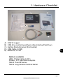
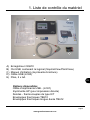
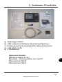
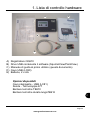
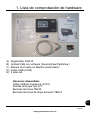
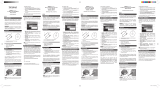
A) OQ610 Logger
B) USB drive containing software (SquirrelView/PaintView)
C) Getting Started manual (this booklet)
D) USB Cable (LC80)
E) Batteries, 2 x AA
Options available
USB - Printer cable (LC81)
Probes - K/T type thermocouples
TB610 Thermal barrier
TB612 Long duration thermal barrier
1. Hardware Checklist
A
B
C
D E

Version 12 28123
Page 3
www.grantinstruments.com
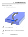
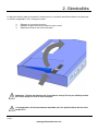
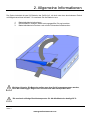
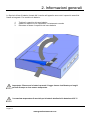
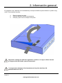
2. General Information
The Squirrel uses 2 x AA* size batteries located under a removable battery door held in place by a
magnetic catch To change the batteries:
1. Lift the battery door and pull forward.
2. Fit new batteries noting correct orientation
3. Refit the battery cover
*Maximum operating temperature for AA alkaline batteries supplied is 50°C
Important: Remove the batteries when the logger is not used for long periods
of time or is being transported.

28123 Version 12
Page 4
www.grantinstruments.com
EN
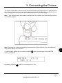
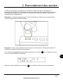
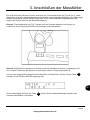
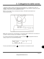
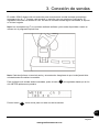
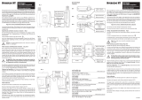
3. Connecting the Probes
The OQ610 is fitted with six thermocouple connector sockets which support K and T type thermocou-
ples. Connect each probe to an input socket, as shown below. The logger will recognise which chan-
nels are being used. If no probes are connected, the Squirrel will not start logging.
Note: T type thermocouples are software controlled and only available when used with SquirrelView
or PaintView software.
Note: Each plug has a wide terminal and a narrow terminal. Ensure that the plug is orientated cor-
rectly before making the connection.
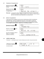
To confirm which probes are connected, press the button on the logger until the METER
function is displayed:-
Func
Repeatedly press the button to view each probe in turn.
Sel

Version 12 28123
Page 5
www.grantinstruments.com
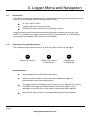
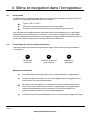
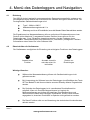
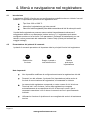
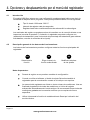
4. Logger Menu and Navigation
Selects the function Chooses the channel
or sub-function
Changes any
of the settings
The OQ610 comes pre-programmed with a default setup providing a basic setup without the
need to use any software. Default settings are as follows:-
4.1 Introduction
K-Type -200 to 1300°C
Logging interval every two seconds
Record up to eight runs before overwriting the oldest.
Logging results may be evaluated immediately by directly connecting to a printer (see
section 7). In addition, the logger can be set up with 'Cure parameters’ for a percentage
cure readout (see software Help content for more details)
The operating buttons allow the set up of all of the major functions of the logger.
4.2 Overview of the operating buttons
Setup changes are not allowed whilst logging
When using the software, the Set button also wakes the Logger for
communication when instructed/required
The logger memory is divided up into a number of runs. When all the runs are
completed, start logging will automatically overwrite the oldest. It is not
necessary to clear any runs in the memory unless specifically required
Only use the reset function on recommendation from technical support
Important Notes:
Func Sel Set

28123 Version 12
Page 6
www.grantinstruments.com
EN
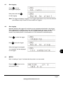
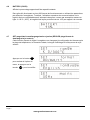
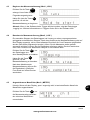
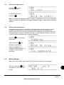
4.3 Start logging
Note: The logger will display “Logging” if no Triggers have been set up from the software
(see software Help Content for more details on Triggers.
Press until the
following is displayed.
Func
4.4 Stop logging
When the logger has stopped
“run complete” will be displayed
on the logger.
Manually stopping the logger will override any pre-programmed automatic ‘stop trigger’.
When logging has completed, the screen will indicate whether the latest run has met its
Cure Specifications (if programmed). For more graphical analysis, either print the
results to a portable printer or download the run into software for detailed analysis.
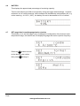
Press to wake the logger.
Func
Hold to stop the logger.
Set
Now press and hold
to start logging.
Set
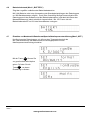
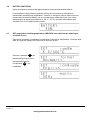
Note: a reading of “open” indicates that the probe is not connected.
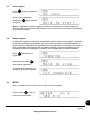
4.5 METER
Press the button to view
each probe in turn.
Sel

Version 12 28123
Page 7
www.grantinstruments.com
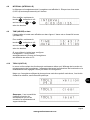
This displays the approximate percentage of remaining capacity.
Two AA cells should give 200 hours operation using the logger default settings. However,
excessive use of communications via the software will dramatically reduce battery life, e.g.
online metering. At -20°C (-22ºF), the battery life can be decreased to 10% of normal.
This allows you to set the Logger up by changing the configuration of the thermocouple
temperature range, the date format, the display language and mains rejection frequency.
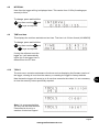
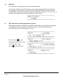
4.7 SET range/date format/language/mains rejection
4.6 BATTERY
Press the button to move
to the desired menu option
then press to change it.
Sel
Set

28123 Version 12
Page 8
www.grantinstruments.com
EN
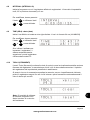
How often the logger will log is displayed here. This can be from 0.125s (8 readings per
second) to 2Hrs.
4.8 INTERVAL
This displays the real time and date on two lines. The time is in 24 hour format (HH:MM:SS)
4.9 TIME and date
If using the software to set the
logger up, it will automatically
inform you if the logger time is
different from the PC time.
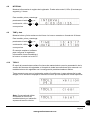
The tools menu contains maintenance functions such as displaying the firmware version of
the logger, clearing all runs from the memory or resetting the logger to factory defaults.
Note that as the logger will record up to 8 runs then overwrite the oldest, it is not necessary
to clear the memory unless specifically required.
4.10 TOOLS
Note: It is recommended that
you only use the reset function
if instructed to do so by a
member of technical support.
To change, press and hold the
key then use the and
keys as required.
Set Sel
Set
To change, press and hold the
key then use the and
keys as required.
Set Sel
Set

Version 12 28123
Page 9
www.grantinstruments.com
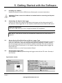
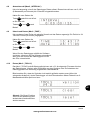
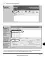
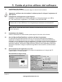
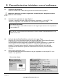
5. Getting Started with the Software
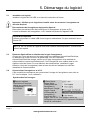
5.1 Installing the software
Install the software from the USB drive by following the on-screen instructions.
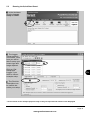
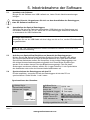
Synchronise clocks:
From
SquirrelView\PaintView
Assistant click on Logger
Setup.
From the Logger
Setup screen select
the Logger Control
tab.
Click on Set Logger
Time to PC Time, click
OK on the confirma-
tion screen.
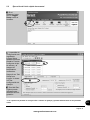
5.3 Startup SquirrelView\PaintView and Select Logger Type
Click on the shortcut icon on your desktop to launch SquirrelView\PaintView or select it
from your start menu. When the SquirrelView\PaintView Assistant is loaded, ensure
the correct logger type and communication method is selected. This can be viewed in
the top right corner of the screen. If you need to make any changes select Logger Se-
lection from the
Assistant toolbar or run the Communication Wizard.
5.4 Synchronise Logger & PC
It is advisable to start by synchronising the Logger clock with the PC clock. See step 1
and 2 below:
Important: Please ensure the software is installed before connecting the Squirrel
data logger.
5.2 Connecting the Squirrel data logger
Connect one end of the supplied USB lead to the logger and the other end to the PC.
On detection of the logger the PC will install the Grant Instruments OQ610 USB device
Win 7,8,10 - USB Device Drivers are automatically installed and no further action is
required
Important information
Only use a USB cable up to 3m in length to maintain CE compliance

28123 Version 12
Page 10
www.grantinstruments.com
EN
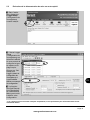
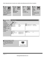
In the Assistant
click the Logger
Setup as shown.
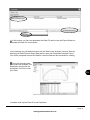
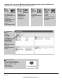
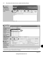
5.5 Running the Quick Start Demo*
* Screen shots are for example purposes only an may not represent the actual screen displayed
The Logger
Setup screen is
now visible. From
here you will be
able to setup your
sensor type and
range required.
Click on ‘Get
Setup from
Logger’ if you
wish to view an
example setup.
The Run/Job
Description can
be used to de-
scribe your setup.

Version 12 28123
Page 11
www.grantinstruments.com
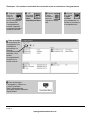
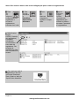
Click
if you
wish to
meter
the input
in Real Time.
Click
to send
setup to
logger
and start
logging. Let the unit
log for a few
minutes.
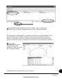
Click for
PaintView/
SquirrelView
Assistant.
Click on
Logger
Control
icon to
pause or stop the
logging process.
In the Logger
Control window
you can view
relevant
information on
the state of the
logger. To stop
logging click on
the stop button.
To Download the logger
click on the ‘Download Data’
icon from the SquirrelView
Assistant.
Note: You must have at least one probe connected before you can start logging.

28123 Version 12
Page 12
www.grantinstruments.com
EN
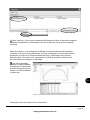
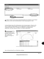
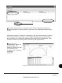
In this screen you can now download the Data File and invoke the Export Wizard or
download the Data File via Analysis*
In this example you will download and view the Data in the Analysis* window. Start by
selecting the Data File and Graph Data action, then click Download Selected File(s).
You will be prompted to save the Data file, then the data will be converted for viewing.
Once the decoding has
taken place the Analysis File
Description window will be
presented, click OK to view
your Data.
*Available with SquirrelView Plus and PaintView.

Version 12 28123
Page 13
www.grantinstruments.com
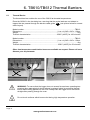
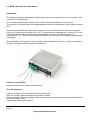
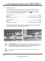
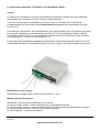
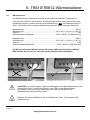
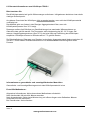
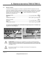
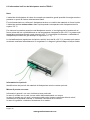
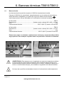
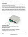
6. TB610/TB612 Thermal Barriers
6.1 Thermal Barrier
The thermal barriers enables the use of the OQ610 at elevated temperatures.
Place the OQ610 in the insulating box, ensuring that the probe leads are not twisted or
trapped but are passed through the barriers cable guide (see picture below for correct
cable Layout)
Model number............................................................................................................TB612
Dimensions.......................................................................... (l x w x h) 245 x 245 x 115mm
Weight............................................................................................................................ 6kg
Thermal characteristics........................................................250ºC (482ºF) for 100 minutes
Model number............................................................................................................TB610
Dimensions.......................................................................... (l x w x h) 245 x 245 x 115mm
Weight............................................................................................................................ 4kg
Thermal characteristics..........................................................250ºC (482ºF) for 50 minutes
Other time/temperature combination boxes are available on request. Please call us to
discuss your requirements.
WARNING: To ensure that the logger does not exceed its maximum operating tem-
perature when appropriate it should always be placed inside its protective thermal
barrier before being placed into the oven. Always take the logger out of the barrier
straight after passing through the oven.
Do not touch surfaces which become hot during high temperature operation.
A
A
A

28123 Version 12
Page 14
www.grantinstruments.com
EN
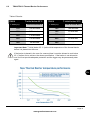
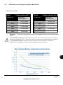
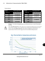
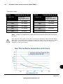
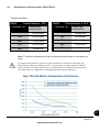
6.2 TB610/TB612 Thermal Barrier Performance
Table of Results:
Important Note: T initial (below 25°C )is the initial temperature of the thermal barrier
before it is placed into the oven.
If the barrier is placed in the oven for a second time it must be allowed to cool below
25°C before use to achieve the above specification. If the barrier is not allowed to
cool it will not provide adequate protection and the logger may be permanently dam-
aged.
T oven (°C) Time to reach 60°C
100 340 minutes
150 195 minutes
200 130 minutes
250 100 minutes
300 30 minutes
T oven (°C) Time to reach 60°C
100 140 minutes
150 80 minutes
200 60 minutes
250 50 minutes
300 -
TB612 T initial below 25°C TB610 T initial below 25°C

Version 12 28123
Page 15
www.grantinstruments.com
Please Note:
The heatsink material is developed to absorb large amounts of heat energy, as a result of this it has
a relatively low melting point.
So it is essential the heatsink should not be used if the heatsink material is in liquid form.
The material will change phase from a solid to a liquid when the temperature of the heatsink is above
32°C.
Therefore the heatsinks are required to be kept cool to ensure they offer the maximum protection
before use. Ideally they should be at 20 - 22°C. In warm ambient temperatures i.e. above 25°C then
it is recommended that the heatsink be cooled/chilled prior to use. A possible solution is a
refrigerator at 7°C) . Failure to cool the barrier between use will result in the logger being permanent-
ly damaged.
Re-crystallisation (change from liquid to solid) will start between 24 and 26°C; cooling in a freezer or
ice bath / cool water bath will speed up this process.
6.3 TBHS-1 Heatsink User Information
Hazardous Information:
Hazard identification of heat sink material: none
First aid measures:
General information: No particular measures are required
After skin contact: Wash immediately with plenty of water
After eye contact: Rinse immediately under running water for several minutes with eyelids held open
and seek medical advice
If swallowed: Seek medical advice

28123 Version 12
Page 16
www.grantinstruments.com
EN
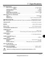
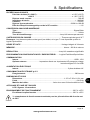
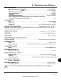
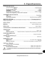
7. Specifications
ANALOGUE INPUTS
Basic accuracy (5-500°C): .............................................................................± 0.5°C (0.9°F)
>500°C ….............................................................................± 1.0°C (1.8°F)
Common mode rejection: ...........................................................................................100dB
Input impedance: ...................................................................................................> 1MOHM
Linearity: .....................................................................................................................0.015%
Series mode line rejection: ............................................................................50/60Hz 100dB
EM field and Conducted RF effect: ………………….………………….……...………….< 1%
ANALOGUE-DIGITAL CONVERSION
Type: ....................................................................................................................Sigma-Delta
Resolution: ......................................................................................................................24bit
Sampling rate: ...........................................................................Up to 8 readings per second
SENSORS SUPPORTED.............................................................................Thermocouple K & T type
Note: Thermocouples are K type as default and T type is only available with SquirrelView software.
TIME AND DATE...........................................................................................In built clock in 3 formats
MEMORY..........................................................................................................Internal: 260K readings
RESOLUTION.................................................................................................Up to 6 significant digits
PROGRAMMING/LOGGER SET-UP................................................PaintView/SquirrelView software
COMMUNICATION
Internal: ................................................................................................................USB 1.1/2.0
External options: ............................Direct printing to HP printers supporting PCL3 and USB
POWER SUPPLY
Internal:............................................................................................2 x AA Alkaline batteries*
POWER CONSUMPTION @ 3V
Logging: ....................................................................................................................>200Hrs
DIMENSIONS AND WEIGHT
Dimensions: .....................................................................................W153 x D23 x H101 mm
Weight: ......................................................................................................................0.415Kg
Enclosure Material: ..................................................Mild steel with a stove enamelled finish
DISPLAY AND KEYPAD
2 line x 16 character LCD
OPERATING ENVIRONMENT ....................................................................................-20°C to +65°C
Using Supplied Batteries:.............................................................................-20°C to +50°C
* Maximum operating temperature for supplied alkaline batteries is 50°C

Version 12 28123
Page 17
www.grantinstruments.com
Due to our policy of continuous improvements, specifications may change without prior notice.
Grant believe that all information declared is correct at the time of issue.
Windows is a registered trademark of Microsoft
Corporation in the United States and other countries.

28123 Version 12
Page 18
www.grantinstruments.com
EN
Personal Notes:

Version 12 28123
Page 1
www.grantinstruments.com
Table des matières
1. Liste de contrôle du materiel .......................................................... 2
2. Généralités ....................................................................................... 3
3. Raccordement des sondes ............................................................. 4
4. Menu et navigation dans l’enregistreur ......................................... 5
5. Initiation au logiciel. ......................................................................... 9
6. Enveloppes thermiques TB610/TB612 ........................................ 13
7. Spécifications ................................................................................. 16
Après avoir lu ce guide, consultez
le contenu de l’Aide dans
SquirrelView ou PaintView (appuyez
sur F1) pour des informations plus
détaillées sur notre enregistreur et
son mode d’emploi avec le logiciel.
La pagina si sta caricando...
La pagina si sta caricando...
La pagina si sta caricando...
La pagina si sta caricando...
La pagina si sta caricando...
La pagina si sta caricando...
La pagina si sta caricando...
La pagina si sta caricando...
La pagina si sta caricando...
La pagina si sta caricando...
La pagina si sta caricando...
La pagina si sta caricando...
La pagina si sta caricando...
La pagina si sta caricando...
La pagina si sta caricando...
La pagina si sta caricando...
La pagina si sta caricando...
La pagina si sta caricando...
La pagina si sta caricando...
La pagina si sta caricando...
La pagina si sta caricando...
La pagina si sta caricando...
La pagina si sta caricando...
La pagina si sta caricando...
La pagina si sta caricando...
La pagina si sta caricando...
La pagina si sta caricando...
La pagina si sta caricando...
La pagina si sta caricando...
La pagina si sta caricando...
La pagina si sta caricando...
La pagina si sta caricando...
La pagina si sta caricando...
La pagina si sta caricando...
La pagina si sta caricando...
La pagina si sta caricando...
La pagina si sta caricando...
La pagina si sta caricando...
La pagina si sta caricando...
La pagina si sta caricando...
La pagina si sta caricando...
La pagina si sta caricando...
La pagina si sta caricando...
La pagina si sta caricando...
La pagina si sta caricando...
La pagina si sta caricando...
La pagina si sta caricando...
La pagina si sta caricando...
La pagina si sta caricando...
La pagina si sta caricando...
La pagina si sta caricando...
La pagina si sta caricando...
La pagina si sta caricando...
La pagina si sta caricando...
La pagina si sta caricando...
La pagina si sta caricando...
La pagina si sta caricando...
La pagina si sta caricando...
La pagina si sta caricando...
La pagina si sta caricando...
La pagina si sta caricando...
La pagina si sta caricando...
La pagina si sta caricando...
La pagina si sta caricando...
La pagina si sta caricando...
La pagina si sta caricando...
La pagina si sta caricando...
La pagina si sta caricando...
La pagina si sta caricando...
La pagina si sta caricando...
La pagina si sta caricando...
La pagina si sta caricando...
-
 1
1
-
 2
2
-
 3
3
-
 4
4
-
 5
5
-
 6
6
-
 7
7
-
 8
8
-
 9
9
-
 10
10
-
 11
11
-
 12
12
-
 13
13
-
 14
14
-
 15
15
-
 16
16
-
 17
17
-
 18
18
-
 19
19
-
 20
20
-
 21
21
-
 22
22
-
 23
23
-
 24
24
-
 25
25
-
 26
26
-
 27
27
-
 28
28
-
 29
29
-
 30
30
-
 31
31
-
 32
32
-
 33
33
-
 34
34
-
 35
35
-
 36
36
-
 37
37
-
 38
38
-
 39
39
-
 40
40
-
 41
41
-
 42
42
-
 43
43
-
 44
44
-
 45
45
-
 46
46
-
 47
47
-
 48
48
-
 49
49
-
 50
50
-
 51
51
-
 52
52
-
 53
53
-
 54
54
-
 55
55
-
 56
56
-
 57
57
-
 58
58
-
 59
59
-
 60
60
-
 61
61
-
 62
62
-
 63
63
-
 64
64
-
 65
65
-
 66
66
-
 67
67
-
 68
68
-
 69
69
-
 70
70
-
 71
71
-
 72
72
-
 73
73
-
 74
74
-
 75
75
-
 76
76
-
 77
77
-
 78
78
-
 79
79
-
 80
80
-
 81
81
-
 82
82
-
 83
83
-
 84
84
-
 85
85
-
 86
86
-
 87
87
-
 88
88
-
 89
89
-
 90
90
-
 91
91
-
 92
92


Grant Instruments OQ610-S Manuale utente
- Tipo
- Manuale utente
in altre lingue
Documenti correlati
Altri documenti
-
Testo TE174T Manuale del proprietario
-
Amprobe TR100-A & TR200-A Temperature Humidity Data Loggers Manuale utente
-
Omega OM-EL-WIN-USB-LCD Manuale del proprietario
-
 Dickson Industrial TM320 Manuale utente
-
TFA Temperature, Humidity and Air Pressure Data Logger LOG32 THP Manuale utente
-
 Oregon Scientific AD105 Manuale utente
-
-
FLIR 407760 Manuale utente
-
 Rotronic HygroLog NT Istruzioni per l'uso
-


