Carel CloudGate-mini Wi-Fi Assembly Procedure
- Tipo
- Assembly Procedure

CloudGate-mini Wi-Fi: Istruzioni di montaggio / Assembly procedure
"CloudGate" +0500170IE - rel. 1.0 - 25.06.2020
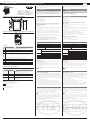
Installazione e montaggio /
Assembly and installation
Dimensioni/forature (in mm) /
Dimensions/drilling template
25
41
48
60
70
Ø 4
25
63.5
Collegamento elettrico, rete RS485 /
Power and RS485 network connection
9..36VDC 9..36VDC
Reset
Serial
TTL
RS485
6
7
8
1
2
3/4
5
Legenda /
key
:
Descrizione
Description
1
Connettore Jack Maschio di alimentazione 5mm positivo al centro 9..36Vdc (*A)
Male Jack Connector Center Poistive power supply 5mm, 9..36Vdc (*A)
2
Connettore per l’alimentazione [+/-] 9..36Vdc (*A)
Power supply connector [+/-] 9..36Vdc
(*A)
3
Led stato dispositivo (Verde/Rosso)
LED device status (Green/Red)
4
Led:
- “Link” Verde acceso fisso = CAREL cloud connesso, gateway configurato;
- “Link” rosso acceso fisso = CAREL cloud connesso, gateway non configurato
Led:
- “Link” Steady Green = CAREL cloud connected, gateway configured;
- “Link” Steady Red = CAREL cloud connected, gateway not configured
5
Reset parametri connessione /
Reset connection parameters
6
Seriale RS485 Non Optoisolata /
RS485 serial not opto-isolated
7
Seriale TTL /
TTL serial port
8
Connettore per antenna Wi-Fi /
Wi-Fi Antenna connector
*A: Nota un solo connettore alla volta può essere usato
*A: a single connector can be used at a time
Signifi cato dei led / Meaning of the LEDs
LED di stato bicolore / Two-colour status LED
Descrizione
Description
LED Stato
Descrizione
Verde / Green Acceso / On
Sistema configurato e connesso al cloud
System configured and connected to the cloud
Verde/Rosso
Green/Red
Spento / Off
Sistema NON configurato e NON connesso al cloud
System NOT con gured and NOT connected to the cloud
Rosso
Red
Acceso / On
Sistema non configurato ma connesso al cloud
System not con gured but connected to the cloud
Rosso/Verde
Red/Green
Lampeggiano
alternativamente
Flash alternately
Il dispositivo si sta avviando o riavviando
System start or restart
LED di alimentazione / Power LED
Colore rosso:
- Acceso: dispositivo alimentato correttamente;
- Spento: dispositivo non alimentato.
Red:
- On: device powered correctly;
- O : device not powered.
Il gateway permette di monitorare un dispositivo collegato in
seriale RS485 e protocollo Modbus RTU mediante una rete Wi-Fi e di
interfacciarsi ad un cloud server.
ATTENZIONE
Quest’apparecchiatura deve essere installata esclusivamente da
personale di servizio con adeguato addestramento tecnico ed
esperienza per essere consapevole dei pericoli a cui può essere
esposto in caso di confi gurazione erronea (installatori abilitati).
NOTE GENERALI
Prima di passare a qualsiasi operazione si raccomanda di controllare
che nella scatola di CloudGate siano presenti:
1. il dispositivo stesso;
2. una antenna tipo Wi-Fi;
3. documentazione tecnica;
4. kit morsetti estraibili.
Evitare il montaggio del prodotto in ambienti che presentino le
seguenti caratteristiche:
• umidità relativa maggiore di quanto indicato nelle speci che
tecniche;
• forti vibrazioni o urti;
• esposizione ad atmosfere aggressive ed inquinanti (es.: gas solforici
e ammoniacali, nebbie saline, fumi) con conseguente corrosione e/o
ossidazione;
• elevate interferenze magnetiche e/o radiofrequenze (evitare quindi
l’installazione delle macchine vicino ad antenne trasmittenti);
• esposizione all’irraggiamento solare diretto e agli agenti atmosferici in
genere;
• ampie e rapide uttuazioni della temperatura ambiente;
• ambienti ove sono presenti esplosivi o miscele di gas in ammabili.
Avvertenze per l’installazione per i modelli con radio
• Prima di installare il prodotto veri care che la zona sia coperta
adeguatamente dal segnale Wi-Fi;
• Posizionare l’antenna al di fuori di carpenterie metalliche.
CARATTERISTICHE TECNICHE
Alimentazione 9..36 Vdc +5% /-5%
Potenza ingresso Max 0.5A@9V
Cond. di Funzionamento -10T60 °C, 90% U.R. non-condensante
Cond. di Stoccaggio -40T70 °C, 90% U.R. non-condensante
Porte seriali 1 RS485 Master non optoisolata
1 TTL 5V
Requisiti di certificazione:
RED:
- WIFI
EN 301 489-1
EN 301 489-17 Ver. 3.1.1 - EN 300 328 Ver. 2.1.1
EN 301 489-52 Ver. 1.1.0 - EN 301 511 Ver. 12.5.1 -
EN 301 908-1 Ver. 11.1.1
FCC:
- WIFI:
FCC Part 15 Subpart B, ICES003
FCC Part 15.31 (k)- ANSI C95.1. MPE - RSS-102. MPE
Safety: 60950; 62368
Grado di inquinamento 2 secondo EN60950-1 / EN62368-1
Grado di protezione IP20
Materiale del contenitore metallo
Non aprire il dispositivo quando alimentato.
Alimentazione
• L’alimentazione del prodotto si deve e ettuare unicamente tramite i
connettori predisposti.
• Lunghezza massima=5 m.
• Usare l’alimentatore PGTA00TRG0, 100/230Vac-24Vdc (10W ±2% 1
modulo DIN, Temperatura minima =-25°C). Collegare il polo positivo
a + e il negativo a -.
ATTENZIONE: utilizzare cavi separati per connessioni seriali e
alimentazione.
LINEE DI COMUNICAZIONE
Linee di comunicazione RS485
La lunghezza massima non deve superare i 1000m, tramite cavo
schermato AWG24, con connessione dello schermo a terra e non a
GND. Le resistenze di terminazione 120 Ω, 1/4W sul primo e sull’ultimo
dispositivo della rete vanno messe se la lunghezza della stessa supera
i 100 m. Le resistenze, incluse nel prodotto, sono da collegare tra i
morsetti seriale + e -:
• rispettare la polarità (-,+,GND);
• non realizzare biforcazioni della linea o collegamenti a stella;
• evitare di posizionare la linea in prossimità delle linee di potenza.
Per migliorare l’immunità del controllo ai disturbi elettromagnetici, il cavo
di collegamento delle seriali deve essere a coppie ritorte (twisted pair)
schermato, bipolare o tripolare in dipendenza dall’isolamento della seriale.
INSTALLAZIONE
Per tutelare la sicurezza degli operatori e la salvaguardia del dispositivo,
prima di e ettuare qualsiasi intervento togliere l’alimentazione. Il
prodotto va installato all’interno di un quadro elettrico, che se di
materiale plastico deve avere grado di in ammabilità 5VA.
Collegare solo le antenne indoor presenti nella confezione.
Se c’è la necessità di installare il prodotto in un quadro metallico è
opportuno remotare l'antenna. Il quadro elettrico metallico deve essere
connesso a terra. A tale scopo utilizzare la prolunga BMBSTEWA00 (Wi-
Fi). La lunghezza massima della prolunga è di 3 m.
Non esporre l’antenna agli agenti atmosferici (pioggia, UV, fulmini, ecc. )
senza adeguata protezione.
L'antenna deve essere installata ad una distanza di almeno 20cm dal
corpo umano.
Una tensione di alimentazione elettrica diversa da quella prescritta può
danneggiare seriamente il sistema.
Utilizzare capicorda adatti per i morsetti in uso. Allentare ogni vite ed
inserirvi i capicorda, quindi serrare le viti. Ad operazione ultimata tirare
leggermente i cavi per veri carne il corretto serraggio.
Non collegare il dispositivo a linee esterne al building.
The gateway allows to monitor an RTU Modbus device connected via
RS485 serial, accessing a WiFi network and communicating with a cloud
server.
WARNING
This appliance must only be installed by service personnel with
suitable technical training and experience and who are aware
of the dangers they may be exposed to in the event of incorrect
confi guration (qualifi ed installers).
GENERAL NOTE
Before performing any operations, check that the CloudGate contains:
1. the device itself;
2. a Wi-Fi antenna;
3. technical documents;
4. terminals kit.
Do not install products in environments with the following
characteristics:
• relative humidity greater than the value speci ed in the technical
speci cations;
• strong vibrations or knocks;
• exposure to aggressive and polluting atmospheres (e.g.: sulphur and
ammonia fumes, saline mist, smoke) so as to avoid corrosion and/or
oxidation;
• strong magnetic and/or radio frequency interference (therefore avoid
installing the units near transmitting antennae);
• exposure to direct sunlight and to the elements in general;
• large and rapid uctuations in the room temperature;
• environments where explosives or mixes of ammable gases are
present.
Installation warnings for Radio models
• Before installing the product make sure the area is su ciently
covered by Wi-Fi signal;
• locate the antenna outside metal hardware.
TECHNICAL SPECIFICATIONS
Power supply 9..36Vdc +5% /-5%
Input power Max 0.5A@9V
Operating conditions -10T60 °C, 90% U.R. non-condensing
Storage conditions -40T70 °C, 90% U.R. non-condensing
Serial Ports 1 RS485 Master non opto-isolated
1 TTL 5V
Certi cation requirements
RED:
- WIFI
EN 301 489-1
EN 301 489-17 Ver. 3.1.1 - EN 300 328 Ver. 2.1.1
EN 301 489-52 Ver. 1.1.0 - EN 301 511 Ver. 12.5.1 -
EN 301 908-1 Ver. 11.1.1
FCC:
- WIFI
FCC Part 15 Subpart B, ICES003
FCC Part 15.31 (k)- ANSI C95.1. MPE - RSS-102. MPE
Safety: 60950; 62368
Pollution degree 2 according to EN60950-1 / EN62368-1
Index of protection IP20
Case material metal
Do not open the device when powered.
Power supply
• Power supply to the product must only be connected to the power
connectors
• Maximum length =5 m.
• If direct current powered use PGTA00TRG0 power supply, 100/230Vac-
24Vdc (10W ±2% 1 DIN-module, Minimum Temperature = -25°C).
• Connect the positive pole to + and negative pole to -.
CAUTION: use separate cables for serial connections and power
supply.
COMMUNICATION LINES
RS485 communication lines
The maximum length must not be over 1000m, via AWG24 shielded
cable, with screen connection to earth and not to GND. The 120Ω
terminal resistors, 1/4W into the rst and the last devices of the network,
must be connected even if the lenght exceeds 100 meters.
The resistors, included in the product, are to be connected between the
serial + and - terminals:
• observe the polarity (+.-,GND);
• do not make branches in the line or star connections;
• avoid laying the line near power cables.
To improve immunity of the controller to electromagnetic disturbance,
the serial connection cable must be twisted pair shielded, twisted two
or three-wire depending on the insulation of the serial connection.
MOUNTING
To safeguard operators and the boards, disconnect power before
performing any operations. The product must be installed inside an
electrical panel; if it is made of plastic material use one with ammability
rating of 5VA.
Connect only the indoor antennas in the package.
If necessary to install the product in a metal electrical panel, it
is recommended to remote the antenna. The metallic electrical
panel must be earthed. Use the extension BMBSTEWA00 (Wi-Fi).
The extention maximum length is 3 m.
Do not expose antenna to the elements (rain, UV lightning, etc.) without
a proper protection.
Antenna must be installed at minimum distance of 20cm from the
human body.
A power supply voltage other than that speci ed will seriously damage
the system;
Use cable ends suitable for the corresponding terminals. Loosen
each screw and insert the cable ends, then tighten the screws. When
the operation is completed, slightly tug the cables to check they are
su ciently tight.
Do not connect the device to external line of building.
Contenuto della confezione
Packaging contents
• Gateway •
Gateway
• Antenna •
Antenna
• Foglio istruzioni •
Instruction sheet
• Morsetti a vite •
Screw terminals

SUPPORTO
SUPPORT
In caso di malfunzionamenti del dispositivo contattare personale di
supporto CAREL. Per ogni dubbio o segnalazione rivolgersi a sw.support@
carel.com
In case of device malfunctions contact CAREL support personnel. For
any questions or concerns, please contact sw.suppor[email protected]
"CloudGate" +0500170IE - rel. 1.0 - 25.06.2020
CAREL INDUSTRIES HQs
Via dell’Industria, 11 – 35020 Brugine – Padova (Italy)
Tel. (+39) 0499716611 – Fax (+39) 0499716600 – e-mail: [email protected] – www.carel.com
CAUTION
This equipment has been tested and found to comply with the limits for a Class B digital device, pursuant
to Part 15 of the FCC Rules. These limits are designed to provide reasonable protection against harmful
interference in a residential installation. This equipment generates, uses and can radiate radio frequency
energy and, if not installed and used in accordance with the instructions, may cause harmful interference
to radio communications. However, there is no guarantee that interference will not occur in a particular
installation. If this equipment does cause harmful interference to radio or television reception, which
can be determined by turning the equipment o and on, the user is encouraged to try to correct the
interference by one of the following measures:
• Reorient or relocate the receiving antenna.
• Increase the separation between the equipment and receiver.
• Connect the equipment into an outlet on a circuit dierent from that to which the receiver is
connected.
• Consult the dealer or an experienced radio/TV technician for help.
FCC Caution: Any changes or modications not expressly approved by the party responsible for
compliance could void the user's authority to operate this equipment.
This device complies with Part 15 of the FCC Rules. Operation is subject to the following two conditions:
(1)
this device may not cause harmful interference, and
(2)
this device must accept any interference received, including interference that may cause undesired
operation.
FCC RF Radiation Exposure Statement:
1. This Transmitter must not be co-located or operating in conjunction with any other antenna or
transmitter.
2. This equipment complies with FCC RF radiation exposure limits set forth for an uncontrolled
environment. This equipment should be installed and operated with a minimum distance of 20
centimeters between the radiator and your body.
CAUTION
1. Never open the equipment. For safety reasons, the equipment should be opened only by qualied
skilled person;
2. can only be safely used lower than 2000 meters altitude
AVVERTENZE GENERALI /
MAIN WARNINGS
REGOLE PER LO SMALTIMENTO / GUIDELINES FOR DISPOSAL
• L’apparecchiatura (o il prodotto) deve essere oggetto di raccolta separata in conformità
alle vigenti normative locali in materia di smaltimento
• Non smaltire il prodotto come riuto solido urbano ma smaltirlo negli appositi centri
di raccolta.
• Un uso improprio o uno smaltimento non corretto potrebbe avere eetti negativi sulla
salute umana e sull’ambiente.
• In caso di smaltimento abusivo dei riuti elettrici ed elettronici sono previste sanzioni
stabilite dalle vigenti normative locali in materia di smaltimento.
•
The appliance (or the product) must be disposed of separately in accordance with the
local waste disposal legislation in force.
•
Do not dispose of the product as municipal waste; it must be disposed of through
specialist waste disposal centres.
•
Improper use or incorrect disposal of the product may negative eects on human
health and on the environment.
•
In the event of illegal disposal of electrical and electronic waste, the penalties are
specied by local waste disposal legislation.
AVVERTENZE IMPORTANTI /
IMPORTANT WARNINGS
Il prodotto CAREL è un prodotto avanzato, il cui funzionamento è specicato nella
documentazione tecnica fornita col prodotto o scaricabile, anche anteriormente all’acquisto, dal
sito internet www.carel.com. Il cliente (costruttore, progettista o installatore dell’equipaggiamento
nale) si assume ogni responsabilità e rischio in relazione alla fase di congurazione del prodotto
per il raggiungimento dei risultati previsti in relazione all’installazione e/o equipaggiamento
nale specico. La mancanza di tale fase di studio, la quale è richiesta/indicata nel manuale
d’uso, può generare malfunzionamenti nei prodotti nali di cui CAREL non potrà essere
ritenuta responsabile. Il cliente nale deve usare il prodotto solo nelle modalità descritte nella
documentazione relativa al prodotto stesso. La responsabilità di CAREL in relazione al proprio
prodotto è regolata dalle condizioni generali di contratto CAREL editate nel sito www.carel.com
e/o da specici accordi con i clienti.
The CAREL product is a state-of-the-art product, whose operation is specied in the technical
documentation supplied with the product or can be downloaded, even prior to purchase, from
the website www.carel.com. - The client (builder, developer or installer of the nal equipment)
assumes every responsibility and risk relating to the phase of conguration the product in order to
reach the expected results in relation to the specic nal installation and/or equipment. The lack of
such phase of study, which is requested/indicated in the user manual, can cause the nal product
to malfunction of which CAREL can not be held responsible. The nal client must use the product
only in the manner described in the documentation related to the product itself. The liability of
CAREL in relation to its own product is regulated by CAREL’s general contract conditions edited on
the website www.carel.com and/or by specic agreements with clients.
MESSA IN SERVIZIO GATEWAY WI-FI
PROCEDURA DI PRIMO ACCESSO
Prima accensione del gateway:
• Ricercare la rete Wi-Fi creata dal gateway, il nome (SSID) di default
della rete creata dal gateway è cgatem-xxxx, dove xxxx corrisponde
agli ultimi byte dell’indirizzo MAC. Il MAC è riportato nell’etichetta
applicata al prodotto.
• Collegarsi a questa rete Wi-Fi con un PC o altri dispositivi
es.Smartphone (di default la rete non ha password alla prima
accensione e dopo un reset dei parametri di connessione).
• Aprire un browser (es. Chrome) e digitare l’indirizzo
http://10.10.100.254.
• Si aprirà una pagina dove verrà chiesto di creare un nuovo nome
utente “user” ed una nuova “password”
ATTENZIONE: Annotate nome utente e password, non vi è modo
di recuperarli se non resettando i parametri.
• Si aprirà una pagina di login dove verrà richiesto di inserire “user” e
“password” appena generati.
• Si aprirà la pagina di congurazione (*), congurare i vari parametri
per la connessione con la propria rete Wi-Fi
• Cliccare su “Submit” al termine dell’operazione, il gateway si
riavvierà e applicherà i nuovi parametri. A questo punto si
verrà sconnessi dalla rete Wi-Fi del gateway (cgatem-xxxx) e
dopo il riavvio il gateway tenterà di collegarsi al cloud CAREL.
Per la registrazione e congurazione del dispositivo collegarsi tramite
PC o tablet alla piattaforma RED, accedere al menù “Congurazione”
e seguire la procedura.
Se richiesto dalla procedura inserire il Serial
Number e il CCV indicati nell’etichetta del prodotto
(Vedi esempio a lato).
Note agguntive per la fase installazione:
Per vericare il livello del segnale radio della rete Wi-Fi in prossimità del
punto di installazione del gateway è suciente utilizzare una delle APP-
free scaricabili da PlayStore/ AppStore, che ne misurano l’intensità e la
distanza “calcolata” dall’access-point. Nel caso il segnale risulti debole
per elevata distanza, o la distanza calcolata dall’APP è molto maggiore
di quella reale, causa ostacoli presenti in ambiente che attenuano il
segnale radio di dell’access-point della rete Wi-Fi, è necessario utilizzare
dei ripetitori di segnale Wi-Fi standard, per estendere/potenziare la rete
Wi-Fi a cui ci si vuole connettere.
(*) La pagina di congurazione consente di modicare l’SSID con cui il
gateway si presenta come access point e permette di aggiungere una
password per proteggere l’accesso. Permette inoltre di personalizzare
l’indirizzo IP al quale visualizzare le pagine di congurazione (default
10.10.100.254). Nella sezione Station Mode si può invece inserire
(manualmente, eettuando uno scan degli AP disponibili o con
modalità WPS, vedi oltre) il nome del SSID (e relativa password) al quale
connettersi. E’ data anche la possibilità di impostare parametri di rete
statici, disabilitando il DHCP e inserendo gli indirizzi desiderati.
Dalla pagina è possibile anche fornire l’url del server NTP al quale si
desidera sincronizzarsi, la porta usata è la standard 123. Inne, possono
essere modicate le credenziali di accesso alle pagine.
FUNZIONE WPS
Per accoppiare attraverso la funzionalità WPS il CloudGate al router Wi-Fi che
fornirà l'accesso a Internet, procedere come indicato di seguito:
• selezionare nella pagina di congurazione WPS;
• premere il pulsante presente nella pagina;
• stimolare ora la funzionalità WPS nel router;
• non appena CloudGate si sarà accoppiato ed ha ricevuto i dati necessari
dal router, esso riparte con i nuovi dati di collegamento.
Nota: la funzionalità WPS rimane attiva (in attesa di accoppiamento)
per circa 2 minuti.
Utilizzo del tasto
Il tasto è utilizzato per diverse funzioni
1. se tenuto premuto all’applicazione dell’alimentazione mette il
gateway in modalità di upgrade via seriale TTL.
2. se premuto per più di 5 secondi e meno di 10 provoca il reboot del
gateway,
3. reset parametri di congurazione (vedi sotto).
FACTORY RESET (RIPRISTINO VALORI DI FABBRICA)
Nel caso vi sia la necessita di riportare il CloudGate alle condizioni di prima
accensione (cancellazione della congurazione, utente e password),
procedere come indicato di seguito:
• con il gateway alimentato
• tenere il tasto premuto per più di 10 secondi, il led Link (Verde)
comincia a lampeggiare lentamente per 10 secondi. Durante questo
lampeggio il tasto va rilasciato. Quando il led verde comincia a
lampeggiare velocemente, premere nuovamente il tasto, questo
forza il reset dei parametri.
ATTENZIONE!
1. È necessario una volta resettato il gateway procedere tramite il portale
CAREL al riaccoppiamento del dispositivo, in caso contrario il gateway
non si ricollegherà al cloud,
2. La procedura descritta non ripristina il rmware di fabbrica se questo
è stato aggiornato.
WIFI GATEWAY START-UP
FIRST COMMISSIONING PROCEDURE
Switching on the gateway for the rst time:
• Search for the Wi-Fi network created by the gateway, the default
name (SSID) of the network created by the gateway is cgatem-xxxx,
where xxxx corresponds to the last bytes of the MAC address. The
MAC address is shown on the label axed to the product.
• Connect to this Wi-Fi network using a PC or other device e.g.
smartphone (by default the network has no password the rst time it
is switched on and after resetting the connection parameters).
• Open a browser (eg Chrome) and enter the address
http://10.10.100.254.
• A page will open for creating a new username "user" and a new
"password"
CAUTION: write down the username and password, as there is no
way to recover these except for resetting the parameters.
• A login page will be shown; enter the newly-generated "user" and
"password".
• The conguration page (*) will be displayed; set the various
parameters for connection to the Wi-Fi network
• Click “Submit” at the end of the operation, the gateway will be rebooted
and the new parameters applied. The device will now be disconnected
from the gateway's Wi-Fi network (cgatem-xxxx), and after
rebooting, the gateway will attempt to connect to the CAREL cloud.
To register and congure the gateway, connect to the RED platform
via PC or tablet, access the “Conguration” menu and follow the
procedure.
If required by the procedure, enter the Serial
Number and the CCV indicated on the product
label (see the example on the side).
Additional notices for installation:
To check the Wi-Fi network radio signal level near where the gateway is
installed, simply use one of the free apps downloadable from PlayStore/
AppStore to measure its intensity and the “calculated” distance from the
access point. If the signal is weak due to a high distance, or the distance
calculated by the app is much greater than the actual distance due to
obstacles in the environment that attenuate the Wi-Fi network access
point signal, use a standard Wi-Fi signal repeater to extend/enhance the
Wi-Fi network signal.
(*) On the conguration page, the SSID that identies the gateway as an
access point can be changed, and a password can be entered to protect
access. The IP address for displaying the conguration pages (default
10.10.100.254) can also be changed. In the Station Mode section, on
the other hand, the name of the SSID (and corresponding password)
to connect to can be entered (manually, by scanning the available APs
or in WPS mode, see below) . It is also possible to set static network
parameters, disabling DHCP and entering the desired addresses.
The url of the NTP server to synchronise with can also be entered; the
port used is the standard, 123. Finally, the credentials for accessing the
pages can also be changed.
WPS FUNCTION
To pair the CloudGate using the WPS function to the Wi-Fi router that
will provide Internet access, proceed as follows:
• open the WPS conguration page;
• click the button on the page;
• activate the WPS function on the router;
• as soon as CloudGate has paired with and received the necessary
data from the router, it will be rebooted with the new connection
data.
Notice: the WPS function remains active (awaiting pairing) for about 2
minutes.
Using the button
The button has various functions
1. if pressed and held at power on, it places the gateway in upgrade
mode via TTL serial.
2. if pressed and held for more than 5 seconds and less than 10, it
reboots the gateway,
3. resetting the conguration parameters (see below).
FACTORY RESET (FACTORY DATA RESET)
If needing to reset CloudGate to the initial conditions (deleting the
conguration, user name and password), proceed as follows:
• with the gateway powered on
• press and hold the button for more than 10 seconds, the Link LED
(green) starts ashing slowly for 10 seconds. When still ashing,
release the button. When the green LED starts ashing quickly, press
the button again, this will reset the parameters.
CAUTION!
1. Once the gateway has been reset, go to the CAREL portal to pair the
device again, otherwise the gateway will not reconnect to the cloud,
2. The procedure described does not restore the factory rmware if this
has been updated.
-
 1
1
-
 2
2


Carel CloudGate-mini Wi-Fi Assembly Procedure
- Tipo
- Assembly Procedure
in altre lingue
- English: Carel CloudGate-mini Wi-Fi
Documenti correlati
-
Carel CloudGate Assembly Procedures
-
-
-
-
-
-
-
-
-