Yamaha PM5D Manuale del proprietario
- Categoria
- Mixer audio
- Tipo
- Manuale del proprietario
Questo manuale è adatto anche per

DIGITAL MIXING CONSOLE
PM5D / PM5D-RHPM5D / PM5D-RH
PM5D / PM5D-RH
Owner’s ManualOwner’s Manual
Owner’s Manual

The above warning is located on the rear of the unit.
Explanation of Graphical Symbols
The lightning flash with arrowhead symbol
within an equilateral triangle is intended to alert
the user to the presence of uninsulated
“dangerous voltage” within the product’s
enclosure that may be of sufficient magnitude to
constitute a risk of electric shock to persons.
The exclamation point within an equilateral
triangle is intended to alert the user to the
presence of important operating and
maintenance (servicing) instructions in the
literature accompanying the product.
IMPORTANT SAFETY INSTRUCTIONS
1 Read these instructions.
2Keep these instructions.
3 Heed all warnings.
4 Follow all instructions.
5 Do not use this apparatus near water.
6 Clean only with dry cloth.
7 Do not block any ventilation openings. Install in
accordance with the manufacturer’s instructions.
8 Do not install near any heat sources such as radiators,
heat registers, stoves, or other apparatus (including
amplifiers) that produce heat.
9 Do not defeat the safety purpose of the polarized or
grounding-type plug. A polarized plug has two blades
with one wider than the other. A grounding type plug
has two blades and a third grounding prong. The wide
blade or the third prong are provided for your safety. If
the provided plug does not fit into your outlet, consult
an electrician for replacement of the obsolete outlet.
10 Protect the power cord from being walked on or pinched
particularly at plugs, convenience receptacles, and the
point where they exit from the apparatus.
11 Only use attachments/accessories specified by the
manufacturer.
12 Use only with the cart, stand,
tripod, bracket, or table specified
by the manufacturer, or sold with
the apparatus. When a cart is
used, use caution when moving
the cart/apparatus combination
to avoid injury from tip-over.
13 Unplug this apparatus during
lightning storms or when unused for long periods of
time.
14 Refer all servicing to qualified service personnel.
Servicing is required when the apparatus has been
damaged in any way, such as power-supply cord or plug
is damaged, liquid has been spilled or objects have
fallen into the apparatus, the apparatus has been
exposed to rain or moisture, does not operate normally,
or has been dropped.
(98-6500)
CAUTION: TO REDUCE THE RISK OF
ELECTRIC SHOCK, DO NOT REMOVE
COVER (OR BACK). NO USER-SERVICEABLE
PARTS INSIDE. REFER SERVICING TO
QUALIFIED SERVICE PERSONNEL.
CAUTION
RISK OF ELECTRIC SHOCK
DO NOT OPEN
WARNING
TO REDUCE THE RISK OF FIRE OR ELECTRIC SHOCK, DO NOT EXPOSE THIS APPARATUS TO RAIN OR MOISTURE.
1. IMPORTANT NOTICE: DO NOT MODIFY THIS UNIT!
This product, when installed as indicated in the instructions con-
tained in this manual, meets FCC requirements. Modifications not
expressly approved by Yamaha may void your authority, granted by
the FCC, to use the product.
2. IMPORTANT:
When connecting this product to accessories and/
or another product use only high quality shielded cables. Cable/s
supplied with this product MUST be used. Follow all installation
instructions. Failure to follow instructions could void your FCC
authorization to use this product in the USA.
3. NOTE:
This product has been tested and found to comply with the
requirements listed in FCC Regulations, Part 15 for Class “B” digital
devices. Compliance with these requirements provides a reason-
able level of assurance that your use of this product in a residential
environment will not result in harmful interference with other elec-
tronic devices. This equipment generates/uses radio frequencies
and, if not installed and used according to the instructions found in
the users manual, may cause interference harmful to the operation
of other electronic devices. Compliance with FCC regulations does
* This applies only to products distributed by YAMAHA CORPORATION OF AMERICA. (class B)
not guarantee that interference will not occur in all installations. If
this product is found to be the source of interference, which can be
determined by turning the unit “OFF” and “ON”, please try to elimi-
nate the problem by using one of the following measures:
Relocate either this product or the device that is being affected by
the interference.
Utilize power outlets that are on different branch (circuit breaker or
fuse) circuits or install AC line filter/s.
In the case of radio or TV interference, relocate/reorient the
antenna. If the antenna lead-in is 300 ohm ribbon lead, change the
lead-in to co-axial type cable.
If these corrective measures do not produce satisfactory results,
please contact the local retailer authorized to distribute this type of
product. If you can not locate the appropriate retailer, please con-
tact Yamaha Corporation of America, Electronic Service Division,
6600 Orangethorpe Ave, Buena Park, CA90620
The above statements apply ONLY to those products distributed by
Yamaha Corporation of America or its subsidiaries.
FCC INFORMATION (U.S.A.)

ADVARSEL!
Lithiumbatteri—Eksplosionsfare ved fejlagtig håndtering. Udskiftning
må kun ske med batteri af samme fabrikat og type. Levér det brugte
batteri tilbage til leverandoren.
VARNING
Explosionsfara vid felaktigt batteribyte. Använd samma batterityp eller
en ekvivalent typ som rekommenderas av apparattillverkaren.
Kassera använt batteri enligt fabrikantens instruktion.
VAROITUS
Paristo voi räjähtää, jos se on virheellisesti asennettu. Vaihda paristo
ainoastaan laitevalmistajan suosittelemaan tyyppiin. Hävitä käytetty
paristo valmistajan ohjeiden mukaisesti.
(lithium caution)
NEDERLAND / THE NETHERLANDS
• Dit apparaat bevat een lithium batterij voor geheugen back-up.
• This apparatus contains a lithium battery for memory back-up.
• Raadpleeg uw leverancier over de verwijdering van de batterij op het
moment dat u het apparaat ann het einde van de levensduur afdankt
of de volgende Yamaha Service Afdeiing:
Yamaha Music Nederland Service Afdeiing
Kanaalweg 18-G, 3526 KL UTRECHT
Tel. 030-2828425
•For the removal of the battery at the moment of the disposal at the
end of the service life please consult your retailer or Yamaha Service
Center as follows:
Yamaha Music Nederland Service Center
Address : Kanaalweg 18-G, 3526 KL UTRECHT
Tel: 030-2828425
• Gooi de batterij niet weg, maar lever hem in als KCA.
• Do not throw away the battery. Instead, hand it in as small chemical
waste.
(lithium disposal)
This product contains a high intensity lamp that contains
a small amount of mercury. Disposal of this material
may be regulated due to environmental considerations.
For disposal information in the United States, refer to
the Electronic Industries Alliance web site:
www.eiae.org
(mercury)* This applies only to products distributed by
YAMAHA CORPORATION OF AMERICA.

(5)-1
1/2
PRECAUTIONS
PLEASE READ CAREFULLY BEFORE PROCEEDING
* Please keep this manual in a safe place for future reference.
WARNING
Always follow the basic precautions listed below to avoid the possibility of serious injury or even death from electrical
shock, short-circuiting, damages, fire or other hazards. These precautions include, but are not limited to, the following:
• Use only the specified power supply (PW800W or an equivalent recommended
by Yamaha).
• Only use the voltage specified as correct for the device. The required voltage is
printed on the name plate of the device.
• Do not place the power cord near heat sources such as heaters or radiators, and
do not excessively bend or otherwise damage the cord, place heavy objects on
it, or place it in a position where anyone could walk on, trip over, or roll anything
over it.
• Do not open the device or attempt to disassemble the internal parts or modify
them in any way. The device contains no user-serviceable parts. If it should
appear to be malfunctioning, discontinue use immediately and have it inspected
by qualified Yamaha service personnel.
• Do not expose the device to rain, use it near water or in damp or wet conditions,
or place containers on it containing liquids which might spill into any openings.
• Never insert or remove an electric plug with wet hands.
• If the power cord or plug becomes frayed or damaged, or if there is a sudden
loss of sound during use of the device, or if any unusual smells or smoke
should appear to be caused by it, immediately turn off the power switch,
disconnect the electric plug from the outlet, and have the device inspected by
qualified Yamaha service personnel.
• If this device or the power supply should be dropped or damaged, immediately
turn off the power switch, disconnect the electric plug from the outlet, and have
the device inspected by qualified Yamaha service personnel.
CAUTION
Always follow the basic precautions listed below to avoid the possibility of physical injury to you or others, or damage
to the device or other property. These precautions include, but are not limited to, the following:
• Remove the electric plug from the outlet when the device is not to be used for
extended periods of time, or during electrical storms.
• When removing the electric plug from the device or an outlet, always hold the
plug itself and not the cord. Pulling by the cord can damage it.
• Do not turn the PW800W POWER switch OFF and ON in rapid succession.
Doing so can result in excessive current flow that can cause damage. Wait at
least 5 seconds before turning the POWER switch ON after it has been turned
OFF.
• When transporting or moving the device, always use four or more people.
• Before moving the device, remove all connected cables.
•Avoid setting all equalizer controls and faders to their maximum. Depending on
the condition of the connected devices, doing so may cause feedback and may
damage the speakers.
• Do not expose the device to excessive dust or vibrations, or extreme cold or heat
(such as in direct sunlight, near a heater, or in a car during the day) to prevent
the possibility of panel disfiguration or damage to the internal components.
• Do not place the device in an unstable position where it might accidentally fall
over.
• Do not block the vents. This device has ventilation holes at the front and rear to
prevent the internal temperature from rising too high. In particular, do not place
the device on its side or upside down, or place it in any poorly-ventilated
location, such as a bookcase or closet.
• Do not use the device in the vicinity of a TV, radio, stereo equipment, mobile
phone, or other electric devices. Otherwise, the device, TV, or radio may
generate noise.
Power supply/Power cord
Do not open
Water warning
If you notice any abnormality
Power supply/Power cord Location

(5)-1
2/2
• Before connecting the device to other devices, turn off the power for all devices.
Before turning the power on or off for all devices, set all volume levels to
minimum.
• Do not insert your fingers or hand in any gaps or openings on the device (vents
etc.).
•Avoid inserting or dropping foreign objects (paper, plastic, metal, etc.) into any
gaps or openings on the device (vents, etc.) If this happens, turn off the power
immediately and unplug the power cord from the AC outlet. Then have the
device inspected by qualified Yamaha service personnel.
• Do not use the headphones for a long period of time at a high or uncomfortable
volume level, since this can cause permanent hearing loss. If you experience
any hearing loss or ringing in the ears, consult a physician.
• Do not rest your weight on the device or place heavy objects on it, and avoid use
excessive force on the buttons, switches or connectors.
• This device has a built-in backup battery. When you unplug the power cord from
the AC outlet, the internal data of current scene is retained. However, if the
backup battery fully discharges, this data will be lost. When the backup battery
is running low, the LCD display indicates “Low Battery!” during operation or
“No Battery!” when starting up the system. In this case, have qualified Yamaha
service personnel replace the backup battery.
XLR-type connectors are wired as follows (IEC60268 standard): pin 1: ground, pin 2: hot (+), and pin 3: cold (-).
Yamaha cannot be held responsible for damage caused by improper use or modifications to the device, or data that is lost or destroyed.
Always turn the power off when the device is not in use.
The performance of components with moving contacts, such as switches, volume controls, and connectors, deteriorates over time. Consult qualified Yamaha service
personnel about replacing defective components.
Connections
Handling caution
Backup battery

6
PM5D/PM5D-RH Owner’s Manual
Table of Contents
Table of Contents — Operating section
1
Introduction ........................................ 10
Thank you................................................................... 10
An overview of the PM5D........................................... 10
Differences between the PM5D model and the
PM5D-RH model ............................................. 11
About the channel structure of the PM5D.......................... 12
Regarding word clock synchronization ....................... 12
How this manual is organized..................................... 13
Conventions in this manual ................................................. 13
2
Top, front, and rear panels................. 14
Top panel ................................................................... 14
Rear panel................................................................... 16
Front panel ................................................................. 18
3
Basic operation on the PM5D............. 19
About the various types of user interface .................... 19
User interface in the display.................................................. 19
DISPLAY ACCESS section ................................................... 20
Data Entry section ................................................................. 20
External user interface........................................................... 21
Basic operation ........................................................... 22
Click........................................................................................ 22
Drag ........................................................................................ 22
Drag and drop........................................................................ 22
Accessing a desired screen..................................................... 23
Moving the cursor ................................................................. 23
Scrolling the screen................................................................ 24
Operating the buttons........................................................... 25
Adjusting the setting of a knob or fader .............................. 25
Assigning a name................................................................... 26
4
Connections and setup ....................... 27
Audio connections ...................................................... 27
Analog audio connections .................................................... 27
Analog output connections .................................................. 28
Digital input/output connections ........................................ 29
Installing an option card....................................................... 30
Word clock connections and settings.......................... 31
About word clock .................................................................. 31
Selecting the word clock master ........................................... 31
Restoring the current scene to the default state.......... 32
5
Input channel operations ................... 33
About the input channels ........................................... 33
AD IN section.............................................................. 35
Items in the AD IN section ................................................... 35
Controlling the input sensitivity and phantom power
(+48V) of the head amp.............................................. 36
INPUT channel strip.................................................... 37
Items in the INPUT channel strip........................................ 37
ST IN/FX RTN channel strip ........................................ 39
Items in the ST IN/FX RTN channel strip........................... 39
FADER FLIP/ENCODER MODE section ........................ 40
Items in the FADER FLIP/ENCODER MODE section...... 40
Various operations for input channels ......................... 41
Selecting the function of the encoders................................. 41
Exchanging the fader and encoder functions...................... 41
Sending a signal from an input channel to the STEREO
bus ................................................................................. 42
Sending the signal from the input channel to a MIX
bus ................................................................................. 43
Enabling/disabling pairing....................................................45
6
Output channel operations .................47
About the output channels..........................................47
MIX section .................................................................49
Items in the MIX section....................................................... 49
Operations in the MIX section ............................................. 49
STEREO A/B channel strip............................................53
Items in the STEREO A/B channel strip..............................53
Operations in the STEREO A/B channel strip ....................54
MATRIX section...........................................................55
Items in the MATRIX section............................................... 55
Operations in the MATRIX section ..................................... 55
7
Using the Selected Channel section ...57
About the SELECTED CHANNEL section......................57
Items in the SELECTED CHANNEL section ...................57
GROUP................................................................................... 57
CHANNEL SELECT.............................................................. 58
DELAY.................................................................................... 58
GAIN/ATTENUATION/ø (Gain / Attenuation / Phase)...59
NOISE GATE ......................................................................... 59
STEREO.................................................................................. 60
COMPRESSOR...................................................................... 60
HPF (High Pass Filter) .......................................................... 61
EQUALIZER .......................................................................... 61
Operations in the SELECTED CHANNEL section ..........62
Selecting a channel and editing its parameters.................... 62
Compressor operations.........................................................63
Gate operations......................................................................64
EQ/HPF operations ...............................................................65
8
Input Patch / Output Patch operations ..66
Changing the input patch settings..............................66
Changing the output patch settings ...........................67
Inserting an external device into a channel .................69
Connecting an external device for insertion........................ 69
Patching the insert-out and insert-in................................... 70
Directly outputting the signal of an input channel ......72
9
Grouping and linking ..........................73
About DCA Groups and Mute Groups.........................73
Items in the ASSIGN MODE section ............................73
Items in the DCA strip .................................................73
Using DCA Groups ......................................................74
Assigning channels to DCA groups...................................... 74
Controlling DCA groups.......................................................75
Using mute groups......................................................75
Assigning channels to mute groups......................................75
Controlling mute groups ......................................................76
Using the Mute Safe function............................................... 76
Using EQ Link and Compressor Link............................77

PM5D/PM5D-RH Owner’s Manual
Table of Contents
7
10
Scene memory..................................79
About scenes .............................................................. 79
Items in the SCENE MEMORY section......................... 80
Using scene memories................................................ 81
Storing a scene........................................................................81
Recalling a scene.....................................................................82
Using PREVIEW mode ................................................. 82
Using the Auto Store function .................................... 83
Using the Direct Recall function.................................. 83
Using the Selective Recall function ............................. 84
Using the Recall Safe function..................................... 86
Using the Fade function.............................................. 87
Using the Tracking Recall function.............................. 88
Using the Global Paste function.................................. 89
11
Monitor and Cue..............................91
About the MONITOR and CUE sections...................... 91
Using the Monitor function ........................................ 92
Items in the MONITOR section ...........................................92
Monitoring a signal................................................................93
Using the Cue/Solo functions ..................................... 94
Items in the CUE section.......................................................94
About CUE mode and SOLO mode.....................................94
Cue and Solo groups..............................................................95
Using the Cue function..........................................................96
Using the Solo function .........................................................96
12
Talkback and Oscillator....................97
About the TALKBACK/OSCILLATOR sections .............. 97
Items in the TALKBACK/OSCILLATOR sections..............97
Using talkback ............................................................ 98
Using the oscillator ..................................................... 99
13
Meters.............................................100
Items in the meter section ........................................ 100
Switching the meter display ..................................... 100
Switching the metering point................................... 101
Specifying the metering point for input channels ............ 101
Specifying the metering point for output channels.......... 101
Viewing the gain reduction of the internal gates and
compressors .................................................. 102
Viewing the gain reduction for input channels ................ 102
Viewing the gain reduction for output channels.............. 102
14
Effects .............................................103
About the internal effects ......................................... 103
Using an internal effect via a MIX bus....................... 104
Inserting an internal effect into a channel................. 105
Basic operations in the effect screen ......................... 106
Recalling settings from the effect library ........................... 106
Editing the effect parameters.............................................. 106
Storing settings in the effect library ................................... 107
Using the Tap Tempo function................................. 108
Using the Freeze effect ............................................. 109
Using optional Add-On Effects.................................. 109
15
Graphic EQ .....................................110
Patching the graphic EQ ...........................................110
Basic graphic EQ operations......................................111
Controlling the graphic EQ from the display ................... 111
Controlling the graphic EQ from the DCA section.......... 111
16
Remote control ..............................113
MIDI on the PM5D ...................................................113
Using program changes to control events.................113
Using control changes to control events ...................115
Using the MIDI Remote function...............................117
Assigning MIDI messages to controllers ........................... 117
Using MIDI remote channels............................................. 121
Transmitting MIDI events when you switch scenes ...122
Using GPI (General Purpose Interface) ......................123
Using GPI IN ....................................................................... 123
Calibrating the GPI IN ports .............................................. 125
Using GPI OUT................................................................... 126
17
Using memory cards......................128
Using memory cards with the PM5D ........................128
Saving files to a memory card ...................................128
Loading files from a memory card.............................130
18
Surround pan.................................132
About surround pan..................................................132
Bus configuration and operation in surround mode..133
About the surround buses .................................................. 133
How the MIX section will operate ..................................... 133
Basic settings for surround buses...............................134
Controlling surround pan..........................................135
Notes regarding surround pan..................................137
19
Other functions..............................138
Using the user defined keys.......................................138
Items in the USER DEFINED section................................ 138
Assigning functions to the User Defined keys................... 138
Executing functions assigned to the User Defined keys... 139
Using the Fader Assign function................................139
Items in the FADER MODE section.................................. 139
Assigning channels to DCA faders..................................... 139
Controlling the channels assigned to DCA faders ............ 140
Locking the PM5D (Security functions) .....................141
Setting the System Password or Console Password.......... 141
Using Parameter Lock or Console Lock............................ 142
Using cascade connections .......................................143
Making cascade connections .............................................. 143
Basic settings for cascade connection ................................ 143
Selecting the buses used for cascade connection .............. 144
Connecting the PM5D to a computer via USB ..........146
Caution when using the USB TO HOST connector ........ 146
Initializing the PM5D’s internal memory ...................147
Adjusting the faders and input/output gain
(Calibration) ..................................................147
Calibrating the faders.......................................................... 148
Adjusting the analog input gain (PM5D-RH model
only)............................................................................ 148
Adjusting the output gain................................................... 148

8
PM5D/PM5D-RH Owner’s Manual
Table of Contents
Table of Contents — Reference section
Information shown in the display.......... 149
Upper part of the display (always visible).................. 149
Main area of the display............................................ 150
Lower part of the display (always visible) .................. 150
Function menu........................................ 151
Global functions...................................... 152
EFFECT functions ...................................................... 152
EFFECT PARAM (Effect parameter) screen..................... 152
EFFECT ASSIGN screen ..................................................... 154
EFFECT LIBRARY screen................................................... 155
GEQ function............................................................ 156
GEQ PARAM (GEQ parameter) screen ............................ 156
GEQ ASSIGN screen ........................................................... 157
GEQ LIBRARY screen......................................................... 158
SCENE function ........................................................ 159
SCENE screen ...................................................................... 159
EVENT LIST screen ............................................................ 161
SELECTIVE RECALL screen.............................................. 164
RECALL SAFE screen.......................................................... 166
FADE TIME screen ............................................................. 167
TRACKING RECALL screen.............................................. 169
GLOBAL PASTE screen...................................................... 170
MIDI REMOTE function............................................. 171
MIDI SETUP screen............................................................ 171
MIDI PGM CHANGE (MIDI program change) screen .. 173
MIDI CTRL CHANGE (MIDI control change) screen ... 174
MIDI REMOTE screen ....................................................... 175
GPI screen ............................................................................ 177
FADER START screen ........................................................ 179
TRANSPORT screen........................................................... 181
DME CONTROL screen..................................................... 182
UTILITY function ....................................................... 186
PREFERENCE 1/2 screens.................................................. 186
USER DEFINE screen ......................................................... 189
SAVE screen ......................................................................... 192
LOAD screen........................................................................ 195
FADER ASSIGN screen....................................................... 197
SECURITY screen................................................................ 198
SYS/W.CLOCK function ............................................ 199
WORD CLOCK screen ....................................................... 199
MIXER SETUP screen......................................................... 200
CASCADE screen ................................................................ 204
HA (Head Amp) screen ...................................................... 206
OUTPUT PORT ATT (Output port attenuation) screen 207
DITHER screen.................................................................... 207
HA LIBRARY screen ........................................................... 208
METER function ........................................................ 209
INPUT METER screen........................................................ 209
OUTPUT METER screen ................................................... 210
INPUT GR (Input Gain Reduction) screen ...................... 211
OUTPUT GR (Output Gain Reduction) screen............... 211
MON/CUE function .................................................. 212
TALKBACK screen.............................................................. 212
OSCILLATOR screen.......................................................... 213
2TR I/O screen..................................................................... 215
MONITOR screen............................................................... 216
CUE/SOLO screen............................................................... 217
Output functions .................................... 220
OUTPUT PATCH function..........................................220
OUTPUT PATCH screen ...................................................220
INSERT PATCH screen ...................................................... 221
INSERT POINT screen .......................................................222
OUTPUT PATCH LIBRARY screen..................................223
OUTPUT INSERT function..........................................224
INSERT IN MIX 1-24 screen.............................................. 224
INSERT IN MATRIX/STEREO/MONITOR screen ........224
HA LIBRARY screen ...........................................................225
OUTPUT EQ function ................................................225
EQ PARAM (EQ Parameter) screen ..................................225
MIX 1-24 screen................................................................... 227
MATRIX/STEREO screen...................................................227
OUTPUT EQ LIBRARY screen..........................................228
OUTPUT COMP function ..........................................229
COMP PARAM (Compressor parameter) screen ............ 229
MIX 1-24 screen................................................................... 231
MATRIX/STEREO screen...................................................231
COMP LIBRARY (Compressor library) screen ................ 232
OUTPUT DELAY function...........................................233
MIX 1-24 screen................................................................... 233
MATRIX/STEREO screen...................................................233
OUTPUT DCA/GROUP function.................................234
DCA GROUP ASSIGN screen............................................ 234
MUTE GROUP ASSIGN screen.........................................235
EQ LINK ASSIGN screen....................................................236
COMP LINK ASSIGN (Compressor link assign) screen .237
MATRIX/ST function..................................................238
MATRIX/ST ROUTING screen .........................................238
MIX to MATRIX VIEW screen ..........................................240
LCR screen ...........................................................................242
SURR SETUP screen ...........................................................244
OUTPUT VIEW function.............................................245
CH VIEW (Channel view) screen ......................................245
SIGNAL FLOW screen........................................................247
FADER VIEW screen ..........................................................249
CH COPY (Channel copy) screen......................................249
OUTPUT CH LIBRARY screen .........................................251

PM5D/PM5D-RH Owner’s Manual Table of Contents 9
Input functions ........................................252
INPUT PATCH function............................................. 252
INPUT PATCH screen ....................................................... 252
DIRECT OUT PATCH screen ........................................... 253
INSERT PATCH screen...................................................... 254
INSERT/DIRECT OUT POINT screen............................. 256
NAME screen....................................................................... 257
INPUT PATCH LIBRARY screen ..................................... 257
INPUT HA/INSERT function ...................................... 258
CH 1-24 (Input channel 1-24) screen ............................... 258
STIN/FXRTN (ST IN/FXRTN channel) screen ............... 258
INSERT 1-24 screen............................................................ 259
INSERT 25-48 screen.......................................................... 259
INSERT STIN screen .......................................................... 259
HA LIBRARY screen........................................................... 260
INPUT ø/EQ function................................................ 260
EQ PARAM (EQ parameter) screen.................................. 260
EQ 1-24 screen..................................................................... 261
EQ 25-48 switch .................................................................. 261
EQ STIN/FXRTN screen .................................................... 261
ø/ATT 1-48 (Phase/Attenuation 1-48) screen .................. 262
ø/ATT STIN/FXRTN (Phase/Attenuation STIN/FXRTN)
screen .......................................................................... 262
INPUT EQ LIBRARY screen.............................................. 263
INPUT GATE/COMP function ................................... 264
GATE PARAM (Gate parameter) screen .......................... 264
COMP PARAM (Compressor parameter) screen............ 266
CH 1-12 (Input channel 1–12) screen............................... 267
CH 13-24 (Input channel 13–24) screen........................... 267
CH 25-36 (Input channel 25–36) screen........................... 267
CH 37-48 (Input channel 37–48) screen........................... 267
ST IN (ST IN channel) screen............................................ 267
GATE LIBRARY screen ...................................................... 268
COMP LIBRARY (Compressor library) screen................ 269
INPUT DELAY function.............................................. 270
CH 1-24 (Input channel 1–24) screen............................... 270
CH 25-48 (Input channel 25–48) screen........................... 270
ST IN (ST IN channel) screen............................................ 270
INPUT DCA/GROUP function ................................... 271
DCA GROUP ASSIGN screen ........................................... 271
MUTE GROUP ASSIGN screen ........................................ 272
EQ LINK ASSIGN screen ................................................... 272
COMP LINK ASSIGN (Compressor link assign) screen. 273
PAN/ROUTING function ........................................... 274
CH to MIX (Channel to mix) screen................................. 274
MIX SEND VIEW screen ................................................... 280
FIX ASSIGN VIEW screen ................................................. 282
LCR screen........................................................................... 283
SURR PARAM (Surround parameter) screen.................. 283
SURR VIEW (Surround view) screen ............................... 285
M/S screen............................................................................ 285
INPUT VIEW function................................................ 286
CH VIEW (Channel view) screen...................................... 286
SIGNAL FLOW screen ....................................................... 287
FADER VIEW screen.......................................................... 288
CH COPY screen................................................................. 289
INPUT CH LIBRARY (Input channel library) screen..... 289
Appendices..............................................290
EQ Library List ...........................................................290
GATE Library List .......................................................291
Compressor Library List.............................................292
Dynamics Parameters................................................294
GATE section....................................................................... 294
COMP section ..................................................................... 295
Effect Library List .......................................................297
Effects Parameters .....................................................298
Effects and tempo synchronization.................................... 307
Scene Memory/Effect Library to Program Change
Table .............................................................308
Parameters that can be assigned to control changes.312
Control change parameter assignments....................314
NRPN parameter assignments...................................331
Channel Library List ..................................................334
Channel parameter behavior when paired ................335
MIDI Data Format .....................................................336
Warning Messages ....................................................343
Error Messages..........................................................344
Troubleshooting........................................................345
General Specifications ...............................................346
Input/output characteristics ......................................348
Electrical characteristics.............................................352
Other Functions ........................................................354
Pin Assignment .........................................................355
Dimensions ...............................................................356
MIDI Implementation Chart......................................357
Index.........................................................................358
PM5D/PM5D-RH Block Diagram.............. End of Manual
PM5D Level Diagram ............................... End of Manual
PM5D-RH Level Diagram ......................... End of Manual
• The illustrations and screen displays as shown in this
Owner’s Manual are for instructional purposes only,
and may be different from the ones on your device.
• The company names and product names in this
Owner’s Manual are the trademarks or registered
trademarks of their respective companies.

10 PM5D/PM5D-RH Owner’s Manual Operating section
Operating section
Thank you
Thank you for purchasing the Yamaha PM5D digital mixing console. In order to take full advantage of the PM5D’s superior
functionality and enjoy years of trouble-free use, please read this manual before you begin using the product. After you have
read the manual, keep it in a safe place.
An overview of the PM5D
The PM5D is a digital mixing console with the following features.
❏ Full digital SR mixing system
The PM5D is a full-digital SR mixing console that takes
advantage of cutting-edge digital audio processing technol-
ogy. 24-bit linear AD/DA converters are used to deliver up
to 110 dB of dynamic range and amazing sound quality. As
input channels, it provides 48 monaural channels, four ste-
reo channels, and four stereo channels for effect return. As
output channels, it provides 24 MIX channels, eight
MATRIX channels, and two STEREO channels. The PM5D
can be used in a wide range of applications. You can assign
desired channels to be controlled by the eight DCA faders
on the panel, and use them as group faders.
❏ PM5D model and PM5D-RH model
In addition to the standard PM5D model that provides
manual control of the head amp for each input, the
PM5D-RH model is also available, providing programma-
ble control of head amp input sensitivity and phantom
power settings. You can choose the model appropriate for
your situation and budget.
❏ Cutting-edge user interface
For the input channels and STEREO A/B channels, dedi-
cated channel strips are provided where you can operate
the fader, pan, cue, and on/off controls. For MIX channels
and MATRIX channels, encoders allow you to control the
send level and master level. The PM5D allows quick and
intuitive operation just as on an analog mixer. In addition,
you can use the SELECTED CHANNEL section to manu-
ally control the principal parameters (delay, EQ, gate,
compressor) of the desired channel.
❏ Eight effect modules / Twelve graphic
EQ modules
Eight high-quality multi-effect modules are built in. Effects
such as reverb, delay, multiband compressor, and various
modulation effects can be routed via internal buses or
inserted into the desired channel. 31-band graphic EQ can
also be inserted into any channel or any output.
❏ Scene memories and libraries
Mix parameters and internal effect settings can be stored in
memory as up to 500 scenes for immediate recall. Effects,
input/output patching, input channel/output channel set-
tings, internal head amp (PM5D-RH model only) or
external head amp settings can be stored in various librar-
ies, independently of scenes.
❏ Digital cascade connection
Up to four PM5D units, or one PM5D and one Yamaha
DM2000/02R96 unit, can be cascade-connected to share
buses in the digital domain. In particular when PM5D
units are cascaded together, operations such as scene sav-
ing and recall can also be linked. Compatible external
devices can also be used as inserts or as extended signal
processors via a cascade connection.
❏ Surround panning
Surround pan functionality allows multi-channel playback
systems to be used, letting you place the signal of an input
channel in two-dimensional space, or move the sound
image forward/backward and left/right. 3-1ch, 5.1ch, and
6.1ch surround modes are available.
❏ I/O card expansion
The rear panel provides four slots in which separately sold
mini-YGDAI cards can be installed. AD cards, DA cards, or
digital I/O cards can be installed in these slots to add inputs
and outputs.
❏ Add-On Effects provide additional effect
types
Separately sold Add-On Effects packages can be installed to
add new effect types for the internal effects. The REV-X
reverb effect sold as an Add-On Effect for the DM2000 or
02R96 is included as standard.
1 Introduction

PM5D/PM5D-RH Owner’s Manual Operating section 11
1
Introduction
Differences between the PM5D model and the PM5D-RH
model
The PM5D is available as the standard PM5D model or as the PM5D-RH model which allows internal head amp settings to be
programmed. These models differ as follows.
❏ PM5D model
• Head amp adjustments (input sensitivity settings,
phantom power (+48V) on/off) for the analog inputs
(INPUT jacks 1–48, ST IN jacks 1–4) are performed
manually, using the controls of the top panel.
• Insert jacks (INSERT IN/OUT jacks) for the monaural
analog inputs (INPUT jacks 1–48) are provided on the
rear panel, allowing external effect processors to be
inserted in the analog domain.
• ST IN jacks 1–4 are only for line level.
• There is no +48V MASTER switch.
❏ PM5D-RH model
• Head amp adjustments (input sensitivity settings,
phantom power (+48V) on/off) for the analog inputs
are controlled from within the screen via software. For
this reason, the top panel does not have head amp con-
trols; instead, indicators showing the presence or
absence of a signal are provided. Head amp settings can
be saved in a library and recalled at any time.
• Insert jacks for the analog inputs are not provided.
• ST IN jacks 1–4 support mic levels through line levels.
Phantom power can also be supplied to ST IN jacks 1–
4.
• The +48V MASTER switch turns all phantom power
(+48V) on/off.
INPUT jacks 1–48ST IN jacks 1–4
INSERT IN/OUT jacks 1–48
INPUT jacks 1–48
ST IN jacks 1–4

2 Introduction
12 PM5D/PM5D-RH Owner’s Manual Operating section
The PM5D provides the following input channels and out-
put channels.
❏ Input channels
This section processes input signals and sends them to the
STEREO bus or MIX buses. There are three types of input
channel, as follows.
• Input channels 1–48
These channels are used to process monaural signals.
By default, the input signals from the monaural analog
input jacks (INPUT jacks 1–48) are assigned to these
channels.
• ST IN channels 1–4
These channels are used to process stereo signals. By
default, the input signals from the stereo analog input
jacks (ST IN jacks 1–4) are assigned to these channels.
• FX RTN channels 1–4
These channels are used mainly to process the return
signals (stereo) from the internal effects. By default, the
left/right output channels of internal effects 1 through
4 are assigned to these channels.
Hint
Signal assignments to the input channels can be changed as
desired.
❏ Output channels
This section mixes the signals sent from input channels
etc., and sends them to the corresponding output jacks or
output buses. There are three types of output channel, as
follows.
• MIX channels 1–24
These process the signals sent from input channels to
MIX buses, and output them from MIX OUT jacks 1
through 24. These channels are used mainly for fold-
back or as sends to external effects. The signals of MIX
channels 1–24 can also be sent to the STEREO bus or
MATRIX buses.
• MATRIX channels 1–8
These process the signals sent from MIX channels or
STEREO A/B channels to MATRIX buses, and output
them from the MATRIX OUT jacks. This allows MIX
channels or STEREO A/B channels to be mixed at the
desired balance for output.
• STEREO A/B channels
These process the signals sent from input channels or
MIX channels, and output them to STEREO OUT
jacks A/B. These channels are used as the main stereo
outputs. Normally, the same signal is sent from the
STEREO A and B channels. However, it is also possible
to use the STEREO B channel as the center channel for
three-channel L/C/R playback.
Regarding word clock synchronization
The signal used to synchronize digital audio signal process-
ing is called “word clock.” Normally, one device transmits
a reference word clock signal, and the other devices receive
this word clock signal and synchronize to it.
In order to transmit or receive digital audio signals to or
from an external device via the PM5D’s digital input/out-
put jacks or via a digital I/O card installed in a slot, the
word clock must be synchronized between the devices. Be
aware that if the word clock is not synchronized, the sig-
nals will not be transmitted correctly, and unpleasant noise
will occur.
Hint
• For details on synchronizing the word clock of the PM5D
and external devices, refer to the explanation of word clock
in Operating section “Chapter 4. Connections and setup”
(
➥
p.31), and to the Reference Section “WORD CLOCK
screen” (
➥
p.199).
• As an exception, digital signals that are not synchronized
with the PM5D can be input via a digital I/O card that con-
tains a sampling rate converter, or via the 2TR IN/OUT
DIGITAL jacks.
About the channel structure of the
PM5D

PM5D/PM5D-RH Owner’s Manual Operating section 13
1
Introduction
How this manual is organized
This owner’s manual is divided into the following three
sections.
❏ Operating section
This section explains the items on the front and rear pan-
els, connections and setup, and how to operate the PM5D’s
basic functionality. In particular if you have not operated a
digital console before, we recommend that you read chap-
ters 2 through 7 first.
❏ Reference section
This section explains the functionality and operation for all
of the PM5D’s screens. Refer to this section when you want
to learn about the items in the screens.
❏ Appendices
This contains various information such as library lists,
parameter lists for the internal effects, the MIDI data for-
mat, and lists of warning messages and error messages.
In this manual, non-locking panel switches that you press
are called “keys,” and those that change their on/off status
when you push them in (locking types) are called
“switches.” Of the control knobs on the panel, those that
turn from a minimum value to a maximum value are
called “knobs,” while those that turn endlessly are called
“encoders.”
Controls located on the panel are enclosed in square brack-
ets [ ] (e.g., [CUE] key, [PAD] switch) in order to
distinguish them from the buttons and knobs displayed in
the screen. For some controls, the section name is listed
before the [ ] (e.g., CH [ON] key, EQ [FREQUENCY]
encoder).
Unless otherwise specified, references to the PM5D apply
to both the PM5D model and the PM5D-RH model. If
specifications differ between the PM5D model and the
PM5D-RH model, such differences will be noted each time
they occur.
Conventions in this manual

2 Top, front, and rear panels
14 PM5D/PM5D-RH Owner’s Manual Operating section
This chapter explains the names and functions of each part of the PM5D. Details for each section of
the top panel are explained in subsequent chapters of this operating section; refer to the appropri-
ate chapter for more information.
Top panel
A AD IN section (PM5D model)
In this section you can adjust the sensitivity of the ana-
log signals being input from the rear panel INPUT
jacks 1–48 and ST IN jacks 1–4, and switch pad, insert,
and phantom power (+48 V) on/off (➥ p.35).
B AD IN section (PM5D-RH model)
This area indicates the presence, peak level, and phan-
tom power (+48V) on/off status of the input signal
from rear panel INPUT jacks 1–48 and ST IN jacks 1–
4.
Hint
For the PM5D-RH model, input sensitivity and phantom power
on/off are controlled by operations in the display (
➥
p.36).
C INPUT channel strip section
This section controls the principal parameters for input
channels 1–48 (➥ p.37).
D FADER FLIP/ENCODER MODE section
Here you can select the parameters controlled by the
faders/encoders of the INPUT channel strip (
3)
(➥ p.40).
E MIX section
This section controls the on/off status and send level of
the signals sent from input channels to MIX buses, and
adjusts the master level of the MIX channels (➥ p.49).
F MATRIX section
This section controls the send level of the signals sent
from MIX channels to MATRIX buses, and adjusts the
master level of the MATRIX channels (➥ p.55).
G SELECTED CHANNEL section
In this section you can view and control the mix
parameters for the currently selected input channel or
output channel (➥ p.57).
H Meter section
This section contains peak level meters that indicate
the input levels of input channels and the output levels
of output channels and cue monitoring, as selected by
key operations (➥ p.100).
2 Top, front, and rear panels
1
(PM5D model)
2
(PM5D-RH model)
4 5
3
6 8
7

PM5D/PM5D-RH Owner’s Manual Operating section 15
2
Top, front, and rear panels
I Display
This display shows the information you need to oper-
ate the PM5D, and lets you make system-wide settings
and control mix parameters for input and output
channels (➥ p.19).
Hint
You can adjust the angle of the display by moving the upper
part of the display frame forward or backward.
Note
Before moving the PM5D, you must lower the display all the
way back until it is fastened in place.
J FADER MODE section
Here you can select the combination of channels or
DCA groups that will be controlled by the faders of the
DCA strip section (
K) (➥ p.73).
K DCA strip section
From this section you can control the channels
assigned to DCA groups 1–8 (➥ p.73).
L ST IN/FX RTN (Stereo in / Effect return)
channel strip section
This section controls the principal parameters of ST IN
channels 1–4 or FX RTN channels 1–4 (➥ p.39).
M STEREO strip section
This section controls the principal parameters of the
STEREO A/B channels (➥ p.53).
N SCENE MEMORY section
This section stores/recalls mix parameters as scene
memories (➥ p.80). Mute operations for mute groups
1–8 are also performed in this section (➥ p.75).
O CUE/MONITOR section
This section selects the monitor source that is output
from the MONITOR OUT jacks, and adjusts the lev-
els. This section also determines the cue point and
monitoring method that will be used when you press a
[CUE] key for a channel (➥ p.91).
P OSCILLATOR/TALKBACK section
This section switches the oscillator or talkback on/off,
and adjusts the talkback level (➥ p.97).
Q DISPLAY ACCESS section
This section selects the functions or screen shown in
the display (➥ p.20).
R USER DEFINED KEYS sections
This section executes the functions that have been
assigned to the User Defined keys [1]–[25] (➥ p.138).
S Data entry section
This section lets you move the pointer (the arrow dis-
played in the screen) or cursor (the red frame
indicating a selection) in the display and edit the
parameter value (➥ p.20).
T ASSIGN MODE section
This section lets you assign mute groups and DCA
groups for control from the panel (➥ p.73).
R
9
Q
R
ST
N O P
8
J
K M L

2 Top, front, and rear panels
16 PM5D/PM5D-RH Owner’s Manual Operating section
Rear panel
A INPUT jacks 1–48 (PM5D model)
These are balanced XLR-3-31 type input jacks for
inputting analog audio signals from line level devices
or microphones. Nominal input level is
–60 dBu to +10 dBu.
B INSERT IN/OUT jacks 1–48 (PM5D model
only)
These are balanced TRS phone type input/output jacks
for inserting external effects or dynamics processors
etc. into INPUT jacks 1–48. Nominal input/output
level is +4 dBu.
C ST IN (Stereo input) jacks 1–4 (PM5D
model)
These are balanced XLR-3-31 type input jacks for
inputting analog audio signals from line level devices.
Nominal input level is –34 dBu to +10 dBu.
D +48V MASTER switch (PM5D-RH model
only)
This is the master phantom power (+48V) switch for
INPUT jacks 1–48 and ST IN jacks 1–4. If this switch is
off, the +48V buttons shown in the display are
unavailable.
E INPUT jacks 1–48 (PM5D-RH model)
These are balanced XLR-3-31 type input jacks for
inputting analog audio signals from line level devices
or microphones. Nominal input level is
–62 dBu to +10 dBu.
F ST IN (Stereo input) jacks 1–4 (PM5D-RH
model)
These are balanced XLR-3-31 type input jacks for
inputting analog audio signals from line level devices
or microphones. Nominal input level is
–62 dBu to +10 dBu.
3 1
2
(PM5D model)
Male XLR plug
1 (ground)
2 (hot)
3 (cold)
1/4" TRS
phone plug
Tip (hot)
Ring (cold)
Sleeve (ground)
Male XLR plug
1 (ground)
2 (hot)
3 (cold)
46
5
(PM5D-RH model)
Male XLR plug
1 (ground)
2 (hot)
3 (cold)
Male XLR plug
1 (ground)
2 (hot)
3 (cold)

PM5D/PM5D-RH Owner’s Manual Operating section 17
2
Top, front, and rear panels
G MIX OUT jacks
These are XLR-3-32 (balanced) jacks that output the
analog signals of MIX channels 1–24. Nominal output
level is +4 dBu.
H LAMP connector
This is a four-pin female XLR output jack for supply-
ing power to a gooseneck lamp. (These jacks are
provided at three locations). The location of these jacks
differs between the PM5D model and the PM5D-RH
model.
I MONITOR OUT jacks
These are XLR-3-32 (balanced) jacks that output the
monitor signal selected in the MONITOR section of
the top panel. Nominal output level is +4 dBu.
Note
Although the various output jacks and 2TR IN ANALOG jacks
have a nominal input/output level of +4 dBu (maximum level is
+24 dBu), an internal switch allows this to be changed to
–2 dBu (maximum level +18 dBu) if necessary. For details,
contact your Yamaha dealer.
J CUE OUT jacks
These are XLR-3-32 (balanced) jacks that output the
cue monitor signal from the channel selected by its
[CUE] key. Nominal output level is +4 dBu.
K STEREO OUT A/B jacks
These are XLR-3-32 (balanced) jacks that output the
analog signals of the STEREO A/B channels. Nominal
output level is +4 dBu.
L MATRIX OUT jacks
These are XLR-3-32 (balanced) jacks that output the
analog signals of MATRIX channels 1–8. Nominal out-
put level is +4 dBu.
M DC POWER INPUT connector
This is a connector for connecting the PW800W power
supply. Use the dedicated cable included with the
PM5D to make the connection.
N 2TR IN ANALOG jacks 1/2
These are XLR-3-31 (balanced) jacks that input stereo
analog signals from an external source. Nominal input
level is +4 dBu.
O TIME CODE INPUT jack
This is an XLR-3-31 (balanced) jack that receives
SMPTE time code (LTC) from an external source.
P TO HOST connector
This is a USB (type B) connector that allows communi-
cation with a computer.
Q GPI connector
This is a D-sub 25-pin female connector that allows
communication with a GPI-equipped external device.
7
8
Female XLR plug
2 (hot)
1 (ground)
3 (cold)
C
RLRL
RLRL
87654321
MJ9KL
Female XLR plug
2 (hot)
1 (ground)
3 (cold)
Female XLR plug
2 (hot)
1 (ground)
3 (cold)
Female XLR plug
2 (hot)
1 (ground)
3 (cold)
Female XLR plug
2 (hot)
1 (ground)
3 (cold)
IN
R
L
R
L
SMPTE
USB
OUT IN
75
ON OFF
21
COAXIAL COAXIALAES/EBU AES/EBU AES/EBU AES/EBU
3
21
3
THRU OUT IN
N X YVUT
Q R S Z aWPO
Male XLR plug
1 (ground)
2 (hot)
3 (cold)
Male XLR plug
1 (ground)
2 (hot)
3 (cold)

2 Top, front, and rear panels
18 PM5D/PM5D-RH Owner’s Manual Operating section
R RS422 REMOTE connector
This is a D-sub 9-pin female connector for remotely
controlling an external device that supports the RS422
protocol.
S HA REMOTE connector
This is a D-sub 9-pin male connector for remotely con-
trolling an external head amp device (e.g., Yamaha
AD8HR or AD824) that supports a special protocol.
T WORD CLOCK IN connector
This is a BNC connector for supplying a word clock
from an external device to the PM5D.
U 75Ω ON/OFF switch
This switch terminates the word clock connection.
Normally you will leave this ON. If a device made by
another manufacturer is connected and word clock
cannot be received correctly, try turning this OFF.
V WORD CLOCK OUT connector
This is a BNC connector for supplying a word clock
from the PM5D to an external device.
W MIDI IN/THRU/OUT connectors
These connectors are used to transmit and receive
MIDI messages to and from external MIDI devices.
The MIDI IN connector receives messages from an
external device, and the MIDI OUT connector trans-
mits messages from the PM5D. Messages received at
the MIDI IN connector are retransmitted without
change from the MIDI THRU connector.
X 2TR OUT DIGITAL (2 track out digital) jacks
1–3
These jacks digitally output the signals of the STEREO
A/B channels. Two types are provided; AES/EBU
(XLR-3-32) jacks (1/2) which output AES/EBU format
signals, and a COAXIAL (RCA phono) jack (3) which
outputs consumer format signals (IEC60958).
Y 2TR IN DIGITAL (2 track in digital) jacks 1–3
These jacks input digital audio from external devices
such as CD players. Two types are provided; AES/EBU
(XLR-3-31) jacks (1/2) which receive AES/EBU format
signals, and a COAXIAL (RCA phono) jack (3) which
receives consumer format signals (IEC60958).
Z CASCADE OUT connector
This is a D-sub half-pitch 68-pin female connector that
can be connected to another PM5D for transmission/
reception of control signals and transmission of audio
signals.
a CASCADE IN connector
This is a D-sub half-pitch 68-pin female connector that
can be connected to another PM5D for transmission/
reception of control signals and reception of audio
signals.
b Fan grille
This is an output grille for the fan that cools the inte-
rior of the console (two locations). Be careful not to
obstruct the fan exhaust.
c SLOT 1–4
These slots allow separately sold mini-YGDAI I/O
cards to be installed to expand the input/output ports.
Front panel
A MEMORY CARD slot
A memory card inserted in this slot can be used to
save/load scene memories or library data. You can use
PCMCIA Type II flash ATA cards, or CompactFlash
cards inserted into a PC card adaptor.
B MOUSE connector
A PS/2 mouse can be connected to this connector and
used to perform operations in the display.
C KEYBOARD connector
A PS/2 keyboard can be connected to this connector
and used to input text or perform operations in the
display.
D PHONES (Headphone) jack
This headphone jack lets you monitor the MONITOR
OUT or CUE signals.
cb
PHONES
KEYBOARD
MOUSE
MEMORY CARD
PHONES
KEYBOARD
MOUSE
MEMORY CARD
12
43
56
12
43
56
1 2 3 4

PM5D/PM5D-RH Owner’s Manual Operating section 19
3
Basic operation on the PM5D
This chapter explains the various types of user interface used to operate the PM5D.
About the various types of user interface
Basic parameters such as mixing and editing the sound of each channel can be controlled by the faders and encoders of the top
panel. However to make more detailed settings, you will need to access the appropriate “function” and edit the parameter val-
ues in the display. The section below explains the various user interface components shown in the display, and how to use
them.
The user interface in the PM5D’s display uses the follow-
ing components.
❏ Pointer
The arrow shown in the display is called the “pointer.” Use
the pointer to select the parameter you want to control
next.
❏ Cursor
The red frame shown in the display is called
the “cursor.” If the cursor encloses a parame-
ter on the screen, that parameter is selected
for operation.
❏ Tabs
The screen names shown in
the upper left of the display
are called “tabs.” Tabs are
used to switch between
screens within the same
function.
❏ Buttons
Buttons in the display are
used to switch parameters
on/off or to select one of
multiple choices. Buttons
that are currently on are dis-
played in green (some
buttons are displayed in red
or blue); buttons that are
turned off are displayed in
gray.
❏ Knobs/Faders/Boxes
Knobs/faders in the display are used to edit parameter val-
ues. The current value is shown in the box. Boxes for which
/ buttons are displayed at left and right allow you to
edit the parameter by using these buttons. (If editing is not
possible, the buttons will be gray.)
If you want to assign a name to a channel or scene, input
characters, numerals, and symbols into the box.
❏ Character palette
This is a “virtual” keyboard used to input characters,
numerals, and symbols into a text input box.
3 Basic operation on the PM5D
User interface in the display
Cursor
Ta b
Buttons turned
off (gray)
Buttons turned
on (green)
Fader
Box
Box
Knob
/ buttons for
editing the value

3 Basic operation on the PM5D
20 PM5D/PM5D-RH Owner’s Manual Operating section
❏ Scroll bar
If the displayed items are too numerous to fit into a single
screen, you can use the scroll bar to view the portion that is
not currently displayed.
The DISPLAY ACCESS section contains keys that access
the desired function or screen in the display.
A Global functions
These keys access functions that affect the entire
PM5D.
B Output functions
These keys access functions that are related to output
channels.
C Input functions
These keys access functions that are related to input
channels.
When you press the key for the desired function, the screen
for that function will appear in the display. By repeatedly
pressing a key you can cycle through the screens included
in that function.
Hint
If you hold down the [SHIFT] key and press a key in the DIS-
PLAY ACCESS section, the screens included in that function
will appear in the reverse order (Page Back function). You can
also use the Page Back function by holding down a key in the
DISPLAY ACCESS section. If you rapidly press a key twice,
you will return to the first screen in that function.
Controllers used to edit settings and values in the display
are gathered into the data entry section.
A [DEC/CANCEL]/[INC/OK] keys
Use these keys to increase or decrease the value of the
parameter where the cursor is located. If the PM5D has
displayed a window asking you to confirm an opera-
tion such as recall or store, these buttons can be used
instead of the CANCEL button and OK button shown
in the window.
B CURSOR [√]/[®]/[π]/[†] keys
These keys are used to move the cursor to the desired
parameter.
C [SHIFT] key
This key can be used in conjunction with the CUR-
SOR [√]/[®]/[π]/[†] keys to move the cursor
rapidly, or in conjunction with the [DATA] encoder or
[DEC]/[INC] keys to change the parameter value
rapidly.
If you hold down the [SHIFT] key and press the
[ENTER] key, the JOB SELECT window will appear,
allowing you to set multiple parameters in a single
operation. (When you move the cursor to a parameter
for which there is a JOB SELECT window, an indica-
tion of “Job Select = [SHIFT] + [ENTER]” will
appear.)
D [ENTER] key
Use this key to switch a button at the cursor location
on/off, or to open a window.
E [DATA] encoder
Use this to increase or decrease the value of the param-
eter where the cursor is located. The parameter value
will change more rapidly if you turn the [DATA]
encoder while holding down the [SHIFT] key.
Scroll bar
DISPLAY ACCESS section
1
2
3
Data Entry section
2
1
6
3
7
4
5
La pagina si sta caricando...
La pagina si sta caricando...
La pagina si sta caricando...
La pagina si sta caricando...
La pagina si sta caricando...
La pagina si sta caricando...
La pagina si sta caricando...
La pagina si sta caricando...
La pagina si sta caricando...
La pagina si sta caricando...
La pagina si sta caricando...
La pagina si sta caricando...
La pagina si sta caricando...
La pagina si sta caricando...
La pagina si sta caricando...
La pagina si sta caricando...
La pagina si sta caricando...
La pagina si sta caricando...
La pagina si sta caricando...
La pagina si sta caricando...
La pagina si sta caricando...
La pagina si sta caricando...
La pagina si sta caricando...
La pagina si sta caricando...
La pagina si sta caricando...
La pagina si sta caricando...
La pagina si sta caricando...
La pagina si sta caricando...
La pagina si sta caricando...
La pagina si sta caricando...
La pagina si sta caricando...
La pagina si sta caricando...
La pagina si sta caricando...
La pagina si sta caricando...
La pagina si sta caricando...
La pagina si sta caricando...
La pagina si sta caricando...
La pagina si sta caricando...
La pagina si sta caricando...
La pagina si sta caricando...
La pagina si sta caricando...
La pagina si sta caricando...
La pagina si sta caricando...
La pagina si sta caricando...
La pagina si sta caricando...
La pagina si sta caricando...
La pagina si sta caricando...
La pagina si sta caricando...
La pagina si sta caricando...
La pagina si sta caricando...
La pagina si sta caricando...
La pagina si sta caricando...
La pagina si sta caricando...
La pagina si sta caricando...
La pagina si sta caricando...
La pagina si sta caricando...
La pagina si sta caricando...
La pagina si sta caricando...
La pagina si sta caricando...
La pagina si sta caricando...
La pagina si sta caricando...
La pagina si sta caricando...
La pagina si sta caricando...
La pagina si sta caricando...
La pagina si sta caricando...
La pagina si sta caricando...
La pagina si sta caricando...
La pagina si sta caricando...
La pagina si sta caricando...
La pagina si sta caricando...
La pagina si sta caricando...
La pagina si sta caricando...
La pagina si sta caricando...
La pagina si sta caricando...
La pagina si sta caricando...
La pagina si sta caricando...
La pagina si sta caricando...
La pagina si sta caricando...
La pagina si sta caricando...
La pagina si sta caricando...
La pagina si sta caricando...
La pagina si sta caricando...
La pagina si sta caricando...
La pagina si sta caricando...
La pagina si sta caricando...
La pagina si sta caricando...
La pagina si sta caricando...
La pagina si sta caricando...
La pagina si sta caricando...
La pagina si sta caricando...
La pagina si sta caricando...
La pagina si sta caricando...
La pagina si sta caricando...
La pagina si sta caricando...
La pagina si sta caricando...
La pagina si sta caricando...
La pagina si sta caricando...
La pagina si sta caricando...
La pagina si sta caricando...
La pagina si sta caricando...
La pagina si sta caricando...
La pagina si sta caricando...
La pagina si sta caricando...
La pagina si sta caricando...
La pagina si sta caricando...
La pagina si sta caricando...
La pagina si sta caricando...
La pagina si sta caricando...
La pagina si sta caricando...
La pagina si sta caricando...
La pagina si sta caricando...
La pagina si sta caricando...
La pagina si sta caricando...
La pagina si sta caricando...
La pagina si sta caricando...
La pagina si sta caricando...
La pagina si sta caricando...
La pagina si sta caricando...
La pagina si sta caricando...
La pagina si sta caricando...
La pagina si sta caricando...
La pagina si sta caricando...
La pagina si sta caricando...
La pagina si sta caricando...
La pagina si sta caricando...
La pagina si sta caricando...
La pagina si sta caricando...
La pagina si sta caricando...
La pagina si sta caricando...
La pagina si sta caricando...
La pagina si sta caricando...
La pagina si sta caricando...
La pagina si sta caricando...
La pagina si sta caricando...
La pagina si sta caricando...
La pagina si sta caricando...
La pagina si sta caricando...
La pagina si sta caricando...
La pagina si sta caricando...
La pagina si sta caricando...
La pagina si sta caricando...
La pagina si sta caricando...
La pagina si sta caricando...
La pagina si sta caricando...
La pagina si sta caricando...
La pagina si sta caricando...
La pagina si sta caricando...
La pagina si sta caricando...
La pagina si sta caricando...
La pagina si sta caricando...
La pagina si sta caricando...
La pagina si sta caricando...
La pagina si sta caricando...
La pagina si sta caricando...
La pagina si sta caricando...
La pagina si sta caricando...
La pagina si sta caricando...
La pagina si sta caricando...
La pagina si sta caricando...
La pagina si sta caricando...
La pagina si sta caricando...
La pagina si sta caricando...
La pagina si sta caricando...
La pagina si sta caricando...
La pagina si sta caricando...
La pagina si sta caricando...
La pagina si sta caricando...
La pagina si sta caricando...
La pagina si sta caricando...
La pagina si sta caricando...
La pagina si sta caricando...
La pagina si sta caricando...
La pagina si sta caricando...
La pagina si sta caricando...
La pagina si sta caricando...
La pagina si sta caricando...
La pagina si sta caricando...
La pagina si sta caricando...
La pagina si sta caricando...
La pagina si sta caricando...
La pagina si sta caricando...
La pagina si sta caricando...
La pagina si sta caricando...
La pagina si sta caricando...
La pagina si sta caricando...
La pagina si sta caricando...
La pagina si sta caricando...
La pagina si sta caricando...
La pagina si sta caricando...
La pagina si sta caricando...
La pagina si sta caricando...
La pagina si sta caricando...
La pagina si sta caricando...
La pagina si sta caricando...
La pagina si sta caricando...
La pagina si sta caricando...
La pagina si sta caricando...
La pagina si sta caricando...
La pagina si sta caricando...
La pagina si sta caricando...
La pagina si sta caricando...
La pagina si sta caricando...
La pagina si sta caricando...
La pagina si sta caricando...
La pagina si sta caricando...
La pagina si sta caricando...
La pagina si sta caricando...
La pagina si sta caricando...
La pagina si sta caricando...
La pagina si sta caricando...
La pagina si sta caricando...
La pagina si sta caricando...
La pagina si sta caricando...
La pagina si sta caricando...
La pagina si sta caricando...
La pagina si sta caricando...
La pagina si sta caricando...
La pagina si sta caricando...
La pagina si sta caricando...
La pagina si sta caricando...
La pagina si sta caricando...
La pagina si sta caricando...
La pagina si sta caricando...
La pagina si sta caricando...
La pagina si sta caricando...
La pagina si sta caricando...
La pagina si sta caricando...
La pagina si sta caricando...
La pagina si sta caricando...
La pagina si sta caricando...
La pagina si sta caricando...
La pagina si sta caricando...
La pagina si sta caricando...
La pagina si sta caricando...
La pagina si sta caricando...
La pagina si sta caricando...
La pagina si sta caricando...
La pagina si sta caricando...
La pagina si sta caricando...
La pagina si sta caricando...
La pagina si sta caricando...
La pagina si sta caricando...
La pagina si sta caricando...
La pagina si sta caricando...
La pagina si sta caricando...
La pagina si sta caricando...
La pagina si sta caricando...
La pagina si sta caricando...
La pagina si sta caricando...
La pagina si sta caricando...
La pagina si sta caricando...
La pagina si sta caricando...
La pagina si sta caricando...
La pagina si sta caricando...
La pagina si sta caricando...
La pagina si sta caricando...
La pagina si sta caricando...
La pagina si sta caricando...
La pagina si sta caricando...
La pagina si sta caricando...
La pagina si sta caricando...
La pagina si sta caricando...
La pagina si sta caricando...
La pagina si sta caricando...
La pagina si sta caricando...
La pagina si sta caricando...
La pagina si sta caricando...
La pagina si sta caricando...
La pagina si sta caricando...
La pagina si sta caricando...
La pagina si sta caricando...
La pagina si sta caricando...
La pagina si sta caricando...
La pagina si sta caricando...
La pagina si sta caricando...
La pagina si sta caricando...
La pagina si sta caricando...
La pagina si sta caricando...
La pagina si sta caricando...
La pagina si sta caricando...
La pagina si sta caricando...
La pagina si sta caricando...
La pagina si sta caricando...
La pagina si sta caricando...
La pagina si sta caricando...
La pagina si sta caricando...
La pagina si sta caricando...
La pagina si sta caricando...
La pagina si sta caricando...
La pagina si sta caricando...
La pagina si sta caricando...
La pagina si sta caricando...
La pagina si sta caricando...
La pagina si sta caricando...
La pagina si sta caricando...
La pagina si sta caricando...
La pagina si sta caricando...
La pagina si sta caricando...
La pagina si sta caricando...
La pagina si sta caricando...
La pagina si sta caricando...
La pagina si sta caricando...
La pagina si sta caricando...
La pagina si sta caricando...
La pagina si sta caricando...
La pagina si sta caricando...
La pagina si sta caricando...
La pagina si sta caricando...
La pagina si sta caricando...
La pagina si sta caricando...
La pagina si sta caricando...
La pagina si sta caricando...
La pagina si sta caricando...
La pagina si sta caricando...
La pagina si sta caricando...
La pagina si sta caricando...
La pagina si sta caricando...
La pagina si sta caricando...
La pagina si sta caricando...
La pagina si sta caricando...
La pagina si sta caricando...
La pagina si sta caricando...
La pagina si sta caricando...
La pagina si sta caricando...
La pagina si sta caricando...
La pagina si sta caricando...
La pagina si sta caricando...
La pagina si sta caricando...
La pagina si sta caricando...
La pagina si sta caricando...
La pagina si sta caricando...
La pagina si sta caricando...
La pagina si sta caricando...
La pagina si sta caricando...
La pagina si sta caricando...
La pagina si sta caricando...
La pagina si sta caricando...
La pagina si sta caricando...
La pagina si sta caricando...
La pagina si sta caricando...
La pagina si sta caricando...
La pagina si sta caricando...
La pagina si sta caricando...
La pagina si sta caricando...
La pagina si sta caricando...
La pagina si sta caricando...
La pagina si sta caricando...
-
 1
1
-
 2
2
-
 3
3
-
 4
4
-
 5
5
-
 6
6
-
 7
7
-
 8
8
-
 9
9
-
 10
10
-
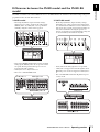 11
11
-
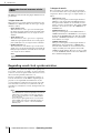 12
12
-
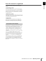 13
13
-
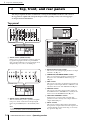 14
14
-
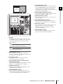 15
15
-
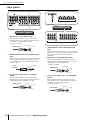 16
16
-
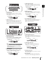 17
17
-
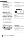 18
18
-
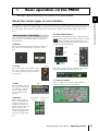 19
19
-
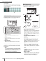 20
20
-
 21
21
-
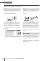 22
22
-
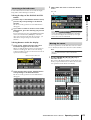 23
23
-
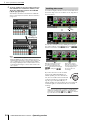 24
24
-
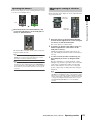 25
25
-
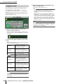 26
26
-
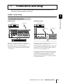 27
27
-
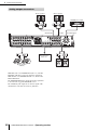 28
28
-
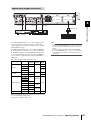 29
29
-
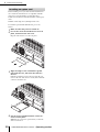 30
30
-
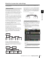 31
31
-
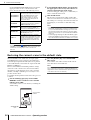 32
32
-
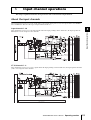 33
33
-
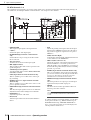 34
34
-
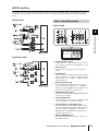 35
35
-
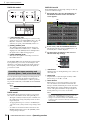 36
36
-
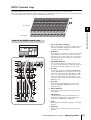 37
37
-
 38
38
-
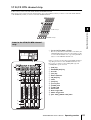 39
39
-
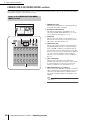 40
40
-
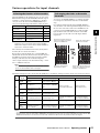 41
41
-
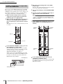 42
42
-
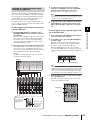 43
43
-
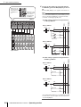 44
44
-
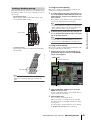 45
45
-
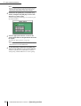 46
46
-
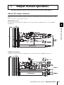 47
47
-
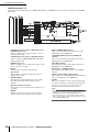 48
48
-
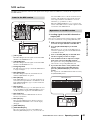 49
49
-
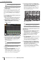 50
50
-
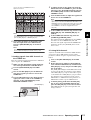 51
51
-
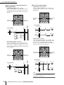 52
52
-
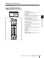 53
53
-
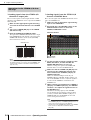 54
54
-
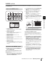 55
55
-
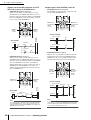 56
56
-
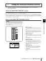 57
57
-
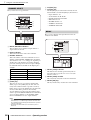 58
58
-
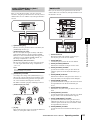 59
59
-
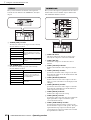 60
60
-
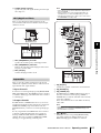 61
61
-
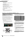 62
62
-
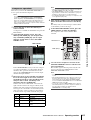 63
63
-
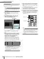 64
64
-
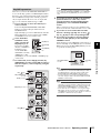 65
65
-
 66
66
-
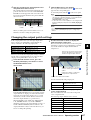 67
67
-
 68
68
-
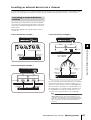 69
69
-
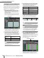 70
70
-
 71
71
-
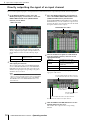 72
72
-
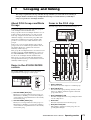 73
73
-
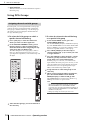 74
74
-
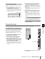 75
75
-
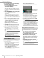 76
76
-
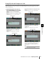 77
77
-
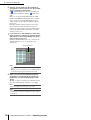 78
78
-
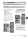 79
79
-
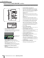 80
80
-
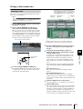 81
81
-
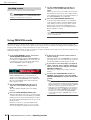 82
82
-
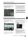 83
83
-
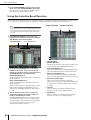 84
84
-
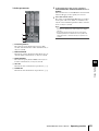 85
85
-
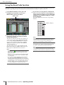 86
86
-
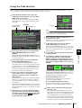 87
87
-
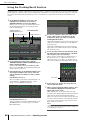 88
88
-
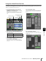 89
89
-
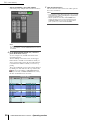 90
90
-
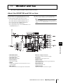 91
91
-
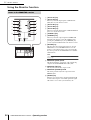 92
92
-
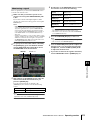 93
93
-
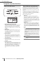 94
94
-
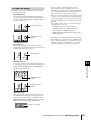 95
95
-
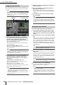 96
96
-
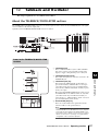 97
97
-
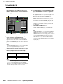 98
98
-
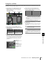 99
99
-
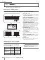 100
100
-
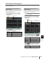 101
101
-
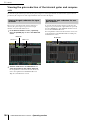 102
102
-
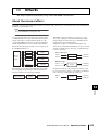 103
103
-
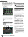 104
104
-
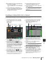 105
105
-
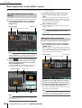 106
106
-
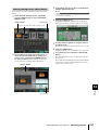 107
107
-
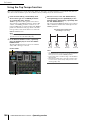 108
108
-
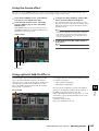 109
109
-
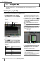 110
110
-
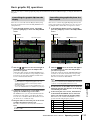 111
111
-
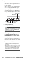 112
112
-
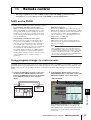 113
113
-
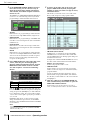 114
114
-
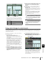 115
115
-
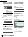 116
116
-
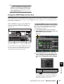 117
117
-
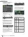 118
118
-
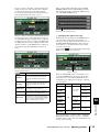 119
119
-
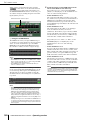 120
120
-
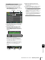 121
121
-
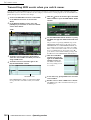 122
122
-
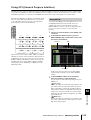 123
123
-
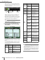 124
124
-
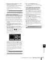 125
125
-
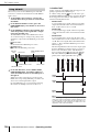 126
126
-
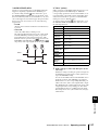 127
127
-
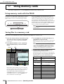 128
128
-
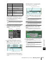 129
129
-
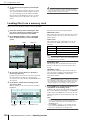 130
130
-
 131
131
-
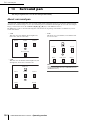 132
132
-
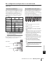 133
133
-
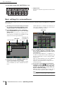 134
134
-
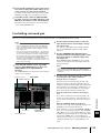 135
135
-
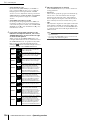 136
136
-
 137
137
-
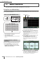 138
138
-
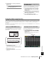 139
139
-
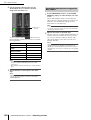 140
140
-
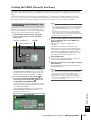 141
141
-
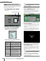 142
142
-
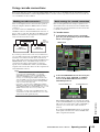 143
143
-
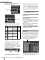 144
144
-
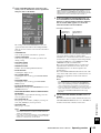 145
145
-
 146
146
-
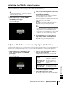 147
147
-
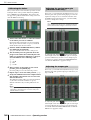 148
148
-
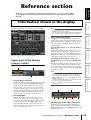 149
149
-
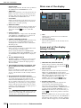 150
150
-
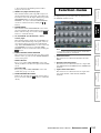 151
151
-
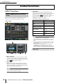 152
152
-
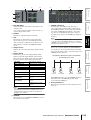 153
153
-
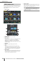 154
154
-
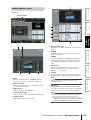 155
155
-
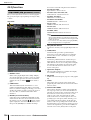 156
156
-
 157
157
-
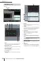 158
158
-
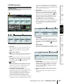 159
159
-
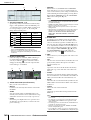 160
160
-
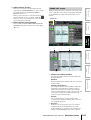 161
161
-
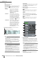 162
162
-
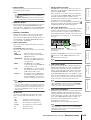 163
163
-
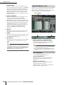 164
164
-
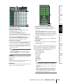 165
165
-
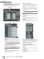 166
166
-
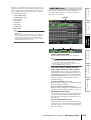 167
167
-
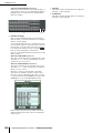 168
168
-
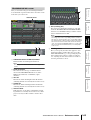 169
169
-
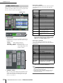 170
170
-
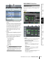 171
171
-
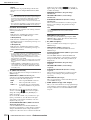 172
172
-
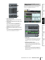 173
173
-
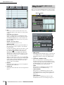 174
174
-
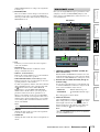 175
175
-
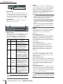 176
176
-
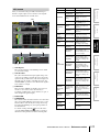 177
177
-
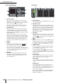 178
178
-
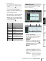 179
179
-
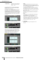 180
180
-
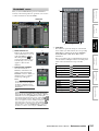 181
181
-
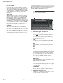 182
182
-
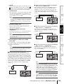 183
183
-
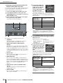 184
184
-
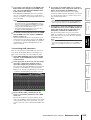 185
185
-
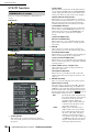 186
186
-
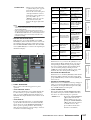 187
187
-
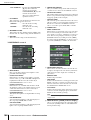 188
188
-
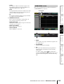 189
189
-
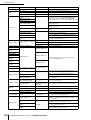 190
190
-
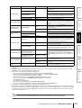 191
191
-
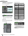 192
192
-
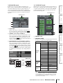 193
193
-
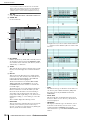 194
194
-
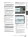 195
195
-
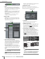 196
196
-
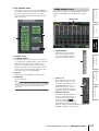 197
197
-
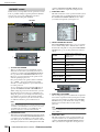 198
198
-
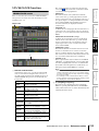 199
199
-
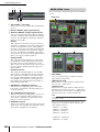 200
200
-
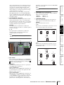 201
201
-
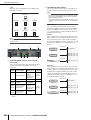 202
202
-
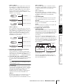 203
203
-
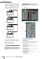 204
204
-
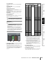 205
205
-
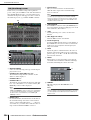 206
206
-
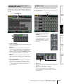 207
207
-
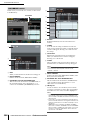 208
208
-
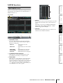 209
209
-
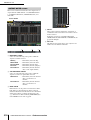 210
210
-
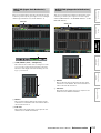 211
211
-
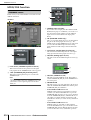 212
212
-
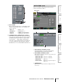 213
213
-
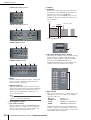 214
214
-
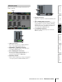 215
215
-
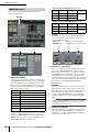 216
216
-
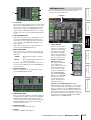 217
217
-
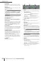 218
218
-
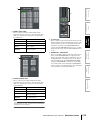 219
219
-
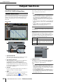 220
220
-
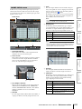 221
221
-
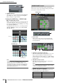 222
222
-
 223
223
-
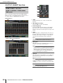 224
224
-
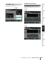 225
225
-
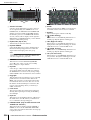 226
226
-
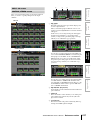 227
227
-
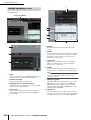 228
228
-
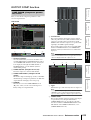 229
229
-
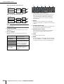 230
230
-
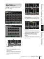 231
231
-
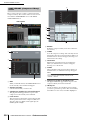 232
232
-
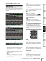 233
233
-
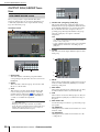 234
234
-
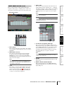 235
235
-
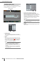 236
236
-
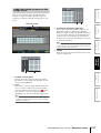 237
237
-
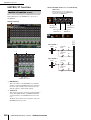 238
238
-
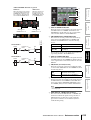 239
239
-
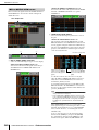 240
240
-
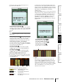 241
241
-
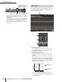 242
242
-
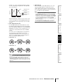 243
243
-
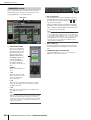 244
244
-
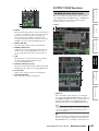 245
245
-
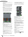 246
246
-
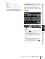 247
247
-
 248
248
-
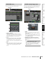 249
249
-
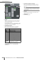 250
250
-
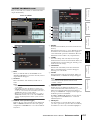 251
251
-
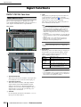 252
252
-
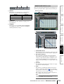 253
253
-
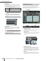 254
254
-
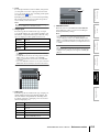 255
255
-
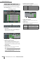 256
256
-
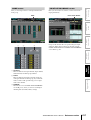 257
257
-
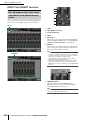 258
258
-
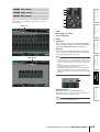 259
259
-
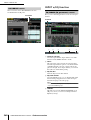 260
260
-
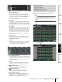 261
261
-
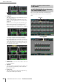 262
262
-
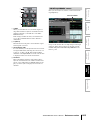 263
263
-
 264
264
-
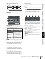 265
265
-
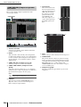 266
266
-
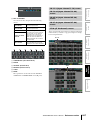 267
267
-
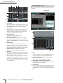 268
268
-
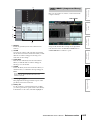 269
269
-
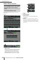 270
270
-
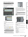 271
271
-
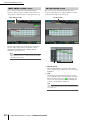 272
272
-
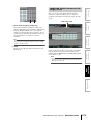 273
273
-
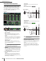 274
274
-
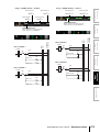 275
275
-
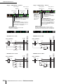 276
276
-
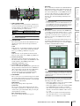 277
277
-
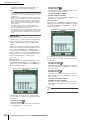 278
278
-
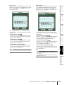 279
279
-
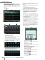 280
280
-
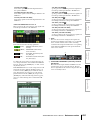 281
281
-
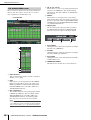 282
282
-
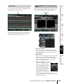 283
283
-
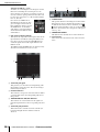 284
284
-
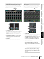 285
285
-
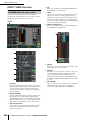 286
286
-
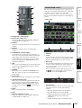 287
287
-
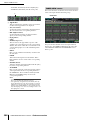 288
288
-
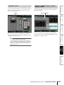 289
289
-
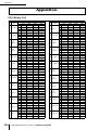 290
290
-
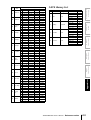 291
291
-
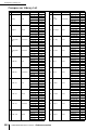 292
292
-
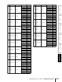 293
293
-
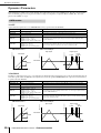 294
294
-
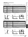 295
295
-
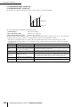 296
296
-
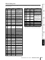 297
297
-
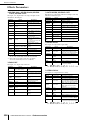 298
298
-
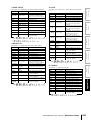 299
299
-
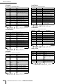 300
300
-
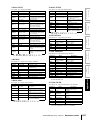 301
301
-
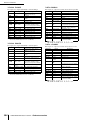 302
302
-
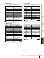 303
303
-
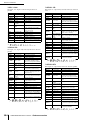 304
304
-
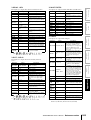 305
305
-
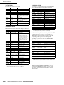 306
306
-
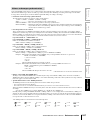 307
307
-
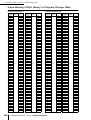 308
308
-
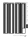 309
309
-
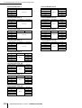 310
310
-
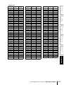 311
311
-
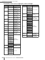 312
312
-
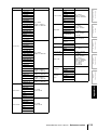 313
313
-
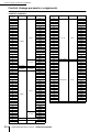 314
314
-
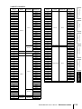 315
315
-
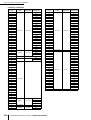 316
316
-
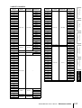 317
317
-
 318
318
-
 319
319
-
 320
320
-
 321
321
-
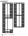 322
322
-
 323
323
-
 324
324
-
 325
325
-
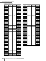 326
326
-
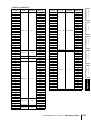 327
327
-
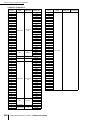 328
328
-
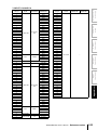 329
329
-
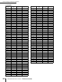 330
330
-
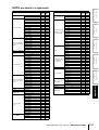 331
331
-
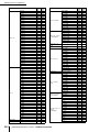 332
332
-
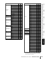 333
333
-
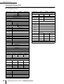 334
334
-
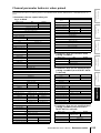 335
335
-
 336
336
-
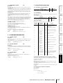 337
337
-
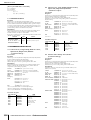 338
338
-
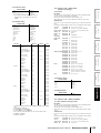 339
339
-
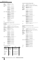 340
340
-
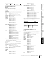 341
341
-
 342
342
-
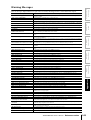 343
343
-
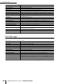 344
344
-
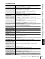 345
345
-
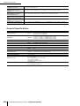 346
346
-
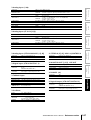 347
347
-
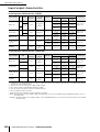 348
348
-
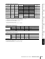 349
349
-
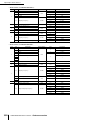 350
350
-
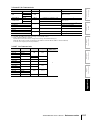 351
351
-
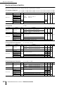 352
352
-
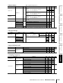 353
353
-
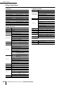 354
354
-
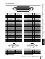 355
355
-
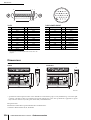 356
356
-
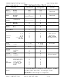 357
357
-
 358
358
-
 359
359
-
 360
360
-
 361
361
-
 362
362
-
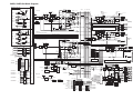 363
363
-
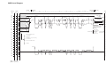 364
364
-
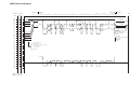 365
365
-
 366
366
-
 367
367


Yamaha PM5D Manuale del proprietario
- Categoria
- Mixer audio
- Tipo
- Manuale del proprietario
- Questo manuale è adatto anche per
in altre lingue
- English: Yamaha PM5D Owner's manual
- français: Yamaha PM5D Le manuel du propriétaire
- español: Yamaha PM5D El manual del propietario
- Deutsch: Yamaha PM5D Bedienungsanleitung
- русский: Yamaha PM5D Инструкция по применению
- Nederlands: Yamaha PM5D de handleiding
- português: Yamaha PM5D Manual do proprietário
- dansk: Yamaha PM5D Brugervejledning
- čeština: Yamaha PM5D Návod k obsluze
- polski: Yamaha PM5D Instrukcja obsługi
- svenska: Yamaha PM5D Bruksanvisning
- Türkçe: Yamaha PM5D El kitabı
- suomi: Yamaha PM5D Omistajan opas
- română: Yamaha PM5D Manualul proprietarului
Documenti correlati
-
Yamaha DSP5D Manuale utente
-
-
Yamaha PM1D Manuale utente
-
-
Yamaha V3 Manuale del proprietario
-
Yamaha CL3 Manuale del proprietario
-
-
-
-
Altri documenti
-
Biamp Rauland All-American Series AP4601 and AP4603 Manuale utente
-
LD Systems AM8 Manuale utente
-
-
TC Electronic M-ONE XL Manuale del proprietario
-
dbx 274 (Project 1) Manuale del proprietario
-
Grace m906 Manuale del proprietario
-
Prince Castle DHB-BK7PC Istruzioni per l'uso