ProLights 91x3 W RGB lime high power full colour LED ellipsoidal Manuale utente
- Categoria
- Stroboscopi
- Tipo
- Manuale utente

ECLIPSEFC
ECLIPSELB05
ECLIPSELB10
ECLIPSELB14
ECLIPSELB19
ECLIPSELB26
ECLIPSELB36
ECLIPSELB50
USER MANUAL
MANUALE UTENTE
ECLIPSEFC
EN - IT
LED PROFILER

All rights reserved by Music & Lights S.r.l. No part of this instruction manual may be
reproduced in any form or by any means for any commercial use.
In order to improve the quality of products, Music&Lights S.r.l. reserves the right to modify the
characteristics stated in this instruction manual at any time and without prior notice.
All revisions and updates are available in the ‘manuals’ section on site www.musiclights.it
REV. 05-11/19

1
ECLIPSEFC
Packing content
• ECLIPSEFC
• Mount bracket
• Power cable
• User manual
TABLE OF CONTENTS
Safety
General instructions
Warnings and installation precautions
1 Introduction
1. 1 Description
1. 2 Technical specifications
1. 3 The configurations
1. 4 Operating elements and connections
2 Installation
2. 1 Mounting
3 Functions and settings
3. 1 Operation
3. 2 Basic
3. 3 Menu structure
3. 4 Static mode
3. 5 Manual mode
3. 6 Master/Slave mode
3. 7 Full on mode
3. 8 White Balance mode
3. 9 Linking
3. 10 DMX configuration
3. 11 DMX mode
3. 12 Connection of the DMX line
3. 13 Construction of the DMX termination
3. 14 DMX control
3. 15 Fixture settings
3. 16 Fixure information
4 Maintenance
4. 1 Maintenance and cleaning the unit
4. 2 Fuse replacement
4. 3 Trouble shooting
2
2
3
3
5
6
7
8
8
9
12
12
12
12
12
13
13
13
15
15
16
19
19
21
21
21

ECLIPSEFC
2
SAFETY
General instruction
• The products referred to in this manual conform to the European Community Directives and are there-
fore marked with .
• The unit is supplied with hazardous network voltage (230V~). Leave servicing to skilled personnel only.
Never make any modifications on the unit not described in this instruction manual, otherwise you will
risk an electric shock.
• Connection must be made to a power supply system fitted with efficient earthing (Class I appliance ac-
cording to standard EN 60598-1). It is, moreover, recommended to protect the supply lines of the units
from indirect contact and/or shorting to earth by using appropriately sized residual current devices.
• The connection to the main network of electric distribution must be carried out by a qualified electrical
installer. Check that the main frequency and voltage correspond to those for which the unit is designed
as given on the electrical data label.
• This unit is not for home use, only professional applications.
• Never use the fixture under the following conditions:
- in places wet;
- in places subject to vibrations or bumps;
- in places with a temperature of over 45 °C.
• Make certain that no inflammable liquids, water or metal objects enter the fixture.
• Do not dismantle or modify the fixture.
• All work must always be carried out by qualified technical personnel. Contact the nearest sales point for
an inspection or contact the manufacturer directly.
• If the unit is to be put out of operation definitively, take it to a local recycling
plant for a disposal which is not harmful to the environment.
Warnings and installation precautions
• If this device will be operated in any way different to the one described in this manual, it may suffer
damage and the guarantee becomes void. Furthermore, any other operation may lead to dangers like
short circuit, burns, electric shock, etc.
• Before starting any maintenance work or cleaning the projector, cut off power from the main supply.
• Always additionally secure the projector with the safety rope. When carrying out any work, always com-
ply scrupulously with all the regulations (particularly regarding safety) currently in force in the country
in which the fixture’s being used.
• Install the fixture in a well ventilated place.
• Keep any inflammable material at a safe distance from the fixture.
• Shields, lenses or ultraviolet screens shall be changed if they have become damaged to such an extent
that their effectiveness is impaired.
• The lamp (LED) shall be changed if it has become damaged or thermally deformed.
• Never look directly at the light beam. Please note that fast changes in lighting, e. g. flashing light, may
trigger epileptic seizures in photosensitive persons or persons with epilepsy.
• Do not touch the product’s housing when operating because it may be very hot.
• This product was designed and built strictly for the use indicated in this documentation. Any other use,
not expressly indicated here, could compromise the good condition/operation of the product and/or
be a source of danger.
• We decline any liability deriving from improper use of the product.
WARNING! Before carrying out any operations with the unit, carefully read this instruction
manual and keep it with cure for future reference. It contains important information about
the installation, usage and maintenance of the unit.

3
ECLIPSEFC
- 1 - INTRODUCTION
1.1 DESCRIPTION
ECLIPSEFC is a full colour LED Ellipsoidal designed to deliver a full range of pastels, whites or saturates
smoothly, consistently and both with or without gobos.
The ECLIPSEFC’s RGB + Lime LED engine has been specially engineered to provide a full spectrum and full
output in the most discerning environments, regardless of which role the ECLIPSEFC is playing.
1.2 TECHNICAL SPECIFICATIONS
LIGHT SOURCE
• Source: 91x3W RGB + lime LEDs
• Luminous flux: (5°) 3’538 lm - (10°) 4’088 lm - (14°) 4’618 lm - (19°) 3’921 lm - (26°) 4’918 lm - (36°) 4’918
lm - (50°) 4’557lm
• Lux: (5°) 36’042 lx - (10°) 17’857 lx - (14°) 9’201 lx - (19°) 5’850 lx - (26°) 3’769 lx - (36°) 2’280 lx, (50°)
1’050lx @3 m full
• Source life expectancy: > 50.000 h
OPTICS
• Beam angle: optional 5° / 10° / 14° / 19° / 26° / 36° / 50° / Z15 - 30° / Z25 - 50°
• Lens type: high-quality glass lens optics
COLOUR SYSTEM
• Colour mixing: RGB + lime / full colour
• CTC: CTC control through independent DMX channel, + / - green and magenta correction and amber
shift activation by DMX
• White presets: 2.700 K ~10.000K
• Macros: built-in white presets
DYNAMIC EFFECTS
• Gobo size: B, outer: 86 mm - image: 64,5 mm - thickness: 1,1 mm
• Static colour mode: selection of static colour
• Manual colour mode: manual adjustment of colour
• Special features: automatic software colour balance when fixture warms up - linear crossfade from a
white to any color and CTO applied on colours
BODY
• Body: sturdy die-cast aluminium body conceived for long-time durability
• Body colour: black, white finishing available
CONTROL
• Protocols: DMX512, RDM
• DMX channels: Theater 1 / 3 / 5 / 17 channel - Tour 4 / 8 / 11channel
• RDM: RDM ready for fixture remote monitor and settings
• Display: black OLED high resolution display
• Firmware upgrade: yes, via USB - DMX interface (UPBOX1) not included
• Master/Slave: for synchronized operation of more units linked in a chain

ECLIPSEFC
4
ELECTRONICS
• Dimmer: linear 0 ~ 100% electronic dimmer
• Dimmer curves: 4 different dimming curves available
• Strobe / shutter: 1 - 30 Hz, electronic
• Battery backup: battery backup for user operation without connecting to the main power
• Operating temperature: -10° ~ +45°
• Flicker: flicker free operation
• Selectable PWM: 600 ~ 25.000 Hz
ELECTRICAL
• Power supply: 100-240 V – 50/60 Hz
• Power consumption (at 230 V): 216W
• Output (at 230 V): 6 units on a single power line
PHYSICAL
• Cooling: combination of heat pipe cooling system and low noise fan
• Sospension and fixing: hanging bracket suitable for safe hanging and positioning
• Signal connection: Amphenol XLR 5p IN/OUT connectors
• Power connection: Neutrik powerCON IN/OUT connectors
• IP rating: 20
• Dimensions (WxHxD): 342x506x530 mm
• Weight: 9 kg
Technical drawing Fig.1
342 528
526

5
ECLIPSEFC
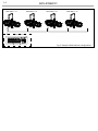
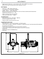
1.3 THE CONFIGURATIONS
Configuration
1 Reflector Housing
Middle part, compatible with
5 °, 10 °, 14 °, 19°, 26°, 36°,
50° optics
2
ECLIPSELB05
Optics for ECLIPSE profiler,
5° beam
ECLIPSELB10
Optics for ECLIPSE profiler,
10° beam
ECLIPSELB14
Optics for ECLIPSE profiler,
14° beam
ECLIPSELB19
Optics for ECLIPSE profiler,
19° beam
ECLIPSELB26
Optics for ECLIPSE profiler,
26° beam
ECLIPSELB36
Optics for ECLIPSE profiler,
36° beam
ECLIPSELB50
Optics for ECLIPSE profiler,
50° beam
ECLIPSEFC
OR

ECLIPSEFC
6
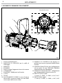
Fig.2
Rear panel
1.4 OPERATING ELEMENTS AND CONNECTIONS
1. MOUNTING BRACKET
2. LOCKING KNOB for the mounting bracket
3. HANDLE
4. ECLIPSEFC
5. SAFETY EYE to attach safety cable.
6. SHUTTER
7. ECLIPSEMP - Aluminium middle part
8. OPTIC
9. FILTER FRAME
10. FUSE OLDER in the event of breakage, always
replace the fuse with the same type and
rating (T3.15A).
11. CONTROL PANEL with display and 4 button
used to access the control panel functions
and manage them.
12. POWER IN (PowerCON IN): for connection to a
socket (100-240V~/50-60Hz) via the supplied
mains cable.
13. POWER OUT (PowerCON OUT): connect to
supply power to the next unit.
14. DMX OUT (5-pole XLR):
1 = ground, 2 = DMX-, 3 = DMX+, 4 N/C, 5 N/C
15. DMX IN (5-pole XLR):
1 = ground, 2 = DMX-, 3 = DMX+, 4 N/C, 5 N/C
1
2
4
5
3
7
6
12
11
13
15
10
14
8
9

Fig.3
CLAMP
SAFETY
CABLE
2
1
7
ECLIPSEFC
- 2 - INSTALLATION
2.1 MOUNTING
ECLIPSEFC may be set up on a solid and even surface. The unit can also be mounted upside down to a
cross arm. For fixing, stable mounting clips are required. The mounting place must be of sufficient stability
and be able to support a weight of 10 times of the unit’s weight.
When carrying out any installation, always comply scrupulously with all the regulations (particularly re-
garding safety) currently in force in the country in which the fixture’s being used.
• Install the projector at a suitable location by means of the mounting bracket (1).
• Always additionally secure the projector with the safety rope from falling down. For this purpose, fas-
ten the safety rope at a suitable position so that the maximum fall of the projector will be 20 cm.
• Adjust the projector and use the knob (2) to slightly release or tighten the locking mechanism of the
bracket if is necessary.

ECLIPSEFC
8
- 3 - FUNCTIONS AND SETTINGS
3.1 OPERATION
Connect the supplied main cable to a socket (100-240 VAC-50/60 Hz). Then the unit is ready for operation
and can be operated via a DMX controller or it independently performs its show program in succession.
To switch off, disconnect the mains plug from the socket. For a more convenient operation it is recom-
mended to connect the unit to a socket which can be switched on and off via a light switch.
3.2 BASIC
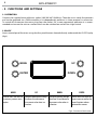
Access control panel functions using the four panel buttons located directly underneath the OLED Display
(fig.4).
MENU UP DOWN ENTER
Used to access the menu or
to return a previous menu
option
Navigates downwards through
the menu list and increases
the numeric value when in a
function
Navigates upwards through
the menu list and decreases
the numeric value when in
a function
Used to select and store the
current menu or confirm the
current function value or
option within a menu
Fig.4 - Functions of the buttons
MENU UP
DOWNENTER

9
ECLIPSEFC
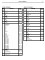
3.3 MENU STRUCTURE
MENU Remark
1 DMX Address
ð
Value (001-512) Default: 001
2 DMX Channel
ð
Theater
ð
1 Ch Default: 8 CH
3 Ch
5 Ch
17 Ch
Tour
ð
4 Ch
8 Ch
11 Ch
3 Full on Mode
ð
HB Mode
Studio Mode
Default: Studio
4 Dimmer Mode
ð
Off Default: Off
Dimmer 1
Works only in DMX Channels
without DIMMER FADE
channel (1, 5, 4, 11)
Dimmer 2
Dimmer 3
5 White Calibrat.
ð
2700K Default: 3200 K
3200K
Not customizable
4200K
5500K
6000K
8000K
Full RGBL RGBL (all 255)
Custom
ð
Red
ð
Value (000-255)
User can see and edit every
single RGBL parameter
Green
ð
Value (000-255)
Blue
ð
Value (000-255)
Lime
ð
Value (000-255)

ECLIPSEFC
10
6 Stand Alone
ð
Master/Slave
ð
Master
Slave
Effects
ð
Effect 1
Effect 2
Effect 3
Effect 4
Effect 5
Statics
ð
Fixed Color
ð
R
G
B
L
RG
RB
RL
GB
GL
BL
RGB
RGL
RBL
GBL
RGBL
Default:
RGBL
ð
Color Temperature
ð
White 2700K
Default:
3200 K
White 3200K
White 4200K
White 5000K
White 5500K
White 6000K
White 7000K
White 8000K
White 9000K
White 10000K
ð
Manual color Mix
ð
Red
ð
Value (000-255)
Green
ð
Value (000-255)
Blue
ð
Value (000-255)
Lime
ð
Value (000-255)

11
ECLIPSEFC
7 White Balance
ð
Off
Manual
ð
Red
Green
Blue
Lime
ð
Value (125-255Value)
8 LED Frequency
ð
600 Hz
1200 Hz
2000 Hz
4000 Hz
25 kHz
Default: 1200 kHz
9 Fan Mode
ð
Auto Speed Default: Auto speed
High Speed
10 Back Light
ð
On Default: 10 s
10 s
20s
30 s
11 Information
ð
Fixture Hours < 9999 H >
Fixture running time
0-9999H
Version < V1.0 > Version number
UID
Settings Reset factory

ECLIPSEFC
12
3.4 STATIC MODE
This fixture has the ability to accept custom static color settings. Access these chases via the control panel
on the back of the fixture.
• Press the button MENU so many times until the display shows STATIC, then press the button ENTER.
• Select Fixed Color through the buttons UP/DOWN, then press the button ENTER.
• Set the colors Red, Green, Blue, Lime, Red Green, Red Blue, Red Lime, Green Blue, Green Lime, Red Green Blue, Red
Green Lime, Red Blue Lime, Green Blue Lime, Red Green Blue Lime, through the buttons UP/DOWN, then press
the button ENTER.
• Select Color Temperature through the buttons UP/DOWN, then press the button ENTER.
• Set the color temperature White 2700K, White 3200K, White 4200K, White 5000K, White 5500K, White 6000K, White
7000K, White 8000K, White 9000K, White 10000K, through the buttons UP/DOWN, then press the button EN-
TER.
• Press the MENU button to go back or to meet the waiting time to exit the setup menu.
3.5 MANUAL MODE
This mode allows to combine the colors red, green, blue and lime.
• Press the button MENU so many times until the display shows STATIC, then press the ENTER button.
• Select STATIC, and next select Manual Color Mixer through the buttons UP/DOWN, then press the ENTER
button.
• Select the color Red, Green, Blue, Lime through the buttons UP/DOWN, then press the ENTER button.
• Using UP/DOWN button, select the desired color value 000 - 255.
• Press ENTER button to continue to the next color Red, Green, Blue, Lime.
• Continue until the desired mix is obtained.
• Press the MENU button to go back or to meet the waiting time to exit the setup menu.
3.6 MASTER/SLAVE MODE
This mode will allow you to link up the units together without a controller. Choose a unit to function as the
Master. The unit must be the first unit in line; other units will work as slave with the same effect.
• Press the button MENU so many times until the display shows STAND ALONE and press the ENTER button.
• Press UP/DOWN to set the unit as master or slave (MASTER, SLAVE).
• Use standard DMX cables to daisy chain your units together via the DMX connector on the rear of the
units. For longer cable runs we suggest a terminator at the last fixture (see page 15).
3.7 FULL ON MODE
• Press the MENU button until FULL ON MODE appears on the display, then press the ENTER button.
• Select the desired mode: HB (High Brightness mode, with maximum color value) or Studio, with an au-
tomatic white balance.
• Press the ENTER key to confirm.
• Press the MENU button to go back or wait a few seconds to exit the setup menu.
3.8 WHITE BALANCE MODE
• To set the white balance, press the MENU button until WHITE BALANCE appears on the display, then press
the ENTER button.
• Use the UP / DOWN keys to select the color: Red, Gree, Blue, Lime. Press ENTER to confirm.
• Use the UP / DOWN keys to set the desired value 125-255.
• Press the ENTER key to continue and go to the next color Red, Gree, Blue or Lime.

13
ECLIPSEFC
• Continue until the desired values are set.
• Press the MENU button to go back or wait a few seconds to exit the setup menu.
3.9 LINKING
1. Connect the DMX OUT of the master unit via 5-pole XLR cable to the DMX IN of the first slave unit.
2. Connect the DMX OUT of the first slave unit to the DMX IN of the second slave unit, etc. until all units
are connected in a chain.
3.10 DMX CONFIGURATION
ECLIPSEFC is equipped with different DMX configuration.
• Press the button MENU so many times until shows DMX CHANNEL, and press the button ENTER to confirm.
• Select THEATER or TOUR through the buttons UP/DOWN, then press the button ENTER.
• Select the desired DMX configuration (1CH - 3CH - 5CH - 17CH or 4CH - 8CH - 11CH) through the buttons UP/
DOWN.
The tables on page 16, 17 e 18 indicate the operating mode and DMX value. The ECLIPSEFC is equipped
with 5-pole XLR connections.
3.11 DMX MODE
• Press the button MENU so many times until the display shows DMX ADDRESS, and press the button ENTER
to confirm.
• Press UP/DOWN button to select the desired value (001-512). Press and hold to scroll quickly.
• Press ENTER button to store.
• Press the MENU button to go back or to meet the waiting time to exit the setup menu.
To able to operate the ECLIPSE with a light controller, adjust the DMX start address for the first a DMX
channel. If e. g. address 33 on the controller is provided for controlling the function of the first DMX
channel, adjust the start address 33 on the ECLIPSE. The other functions of the light effect panel are then
automatically assigned to the following addresses.
An example with the start address 33 is shown below:
Number of
DMX channels
Start address
(example)
DMX Address
occupied
Next possible start
address for unit No. 1
Next possible start
address for unit No. 2
Next possible start
address for unit No. 3
1 33 33 34 35 36
3 33 33-34 35 37 39
4 33 33-36 37 41 45
5 33 33-37 38 43 48
8 33 33-40 41 49 57
11 33 33-43 44 55 66
17 33 33-49 50 67 84

ECLIPSEFC
14
DMX Address: 48DMX Address: 38DMX Address: 33 DMX Address: 43
Fig.5 - Example 5 DMX channels configuration
DMX512 Controller
. . . . . . . . . . . .

15
ECLIPSEFC
Fig.6
Fig.7
3.12 CONNECTION OF THE DMX LINE
DMX connection employs standard XLR connectors. Use shielded pair-twisted cables with 120Ω imped-
ance and low capacity.
The following diagram shows the connection mode:
ATTENTION
The screened parts of the cable (sleeve) must never be connected to the system’s earth, as this would
cause faulty fixture and controller operation.
Over long runs can be necessary to insert a DMX level matching amplifier.
For those connections the use of balanced microphone cable is not recommended because it cannot
transmit control DMX data reliably.
• Connect the controller DMX input to the DMX output of the first unit.
• Connect the DMX output to the DMX input of the following unit. Connect again the output to the input
of the following unit until all the units are connected in chain.
• When the signal cable has to run longer distance is recommended to insert a DMX termination on the
last unit.
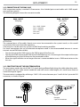
3.13 CONSTRUCTION OF THE DMX TERMINATION
The termination avoids the risk of DMX 512 signals being reflected back along the cable when they reach-
es the end of the line: under certain conditions and with certain cable lengths, this could cause them to
cancel the original signals.
The termination is prepared by soldering a 120Ω 1/4 W resistor between pins 2 and 3 of the 5-pin male XLR
connector, as shown in figure.
DMX - OUTPUT
XLR socket
DMX - INPUT
XLR plug
Pin1 : GND - Shield
Pin2 : - Negative
Pin3 : + Positive
Pin4 : N/C
Pin5 : N/C
Example:
5 pin XLR connector
4

ECLIPSEFC
16
3.14 DMX CONTROL
THEATER - 1 CHANNEL
MODE
FUNCTION DMX
Value
1 Ch
1
DIMMER
0~100% 000 - 255
NOTE - CHOOSE THE COLOR PRESET IN WHITE CALIBRATION
THEATER - 3 CHANNELS
MODE
FUNCTION DMX
Value
3 Ch
1
DIMMER
0~100% 000 - 255
2
WHITE PRESET
White 2700K
White 3200K
White 4200K
White 5000K
White 5500K
White 6000K
White 7000K
White 8000K
White 9000K
White 10000K
000 - 026
027 - 051
052 - 076
077 - 101
102 - 126
127 - 151
152 - 176
177 - 201
202 - 226
227 - 255
3
DIMMER FADE
0~100% (0-1,5 s) 000 - 255
TOUR - 4 CHANNELS
MODE
FUNCTION DMX
Value
4 Ch
1
RED
0~100% 000 - 255
2
GREEN
0~100% 000 - 255
3
BLUE
0~100% 000 - 255
4
LIME
0~100% 000 - 255
THEATER - 5 CHANNELS
MODE
FUNCTION DMX
Value
5 Ch
1
DIMMER
0~100% 000 - 255
2
RED
0~100% 000 - 255
3
GREEN
0~100% 000 - 255
4
BLUE
0~100% 000 - 255
5
LIME
0~100% 000 - 255

17
ECLIPSEFC
TOUR - 11 CHANNELS
MODE
FUNCTION DMX
Value
11 Ch
1
DIMMER
0~100% 000 - 255
2
DIMMER FINE
0~100% 000 - 255
3
RED
0~100% 000 - 255
4
RED FINE
0~100% 000 - 255
5
GREEN
0~100% 000 - 255
6
GREEN FINE
0~100% 000 - 255
7
BLUE
0~100% 000 - 255
8
BLUE FINE
0~100% 000 - 255
9
LIME
0~100% 000 - 255
10
LIME FINE
0~100% 000 - 255
11
STROBE
No Function
Strobe slow to fast
000 - 010
011 - 255
TOUR - 8 CHANNELS
MODE
FUNCTION DMX
Value
8 Ch
1
DIMMER
0~100% 000 - 255
2
RED
0~100% 000 - 255
3
GREEN
0~100% 000 - 255
4
BLUE
0~100% 000 - 255
5
LIME
0~100% 000 - 255
6
COLOR PRESET
No Function
Red
Green
Blue
Lime
Cyan
Magenta
Yellow
Orange
Light Yellow
Light Blue
Light Pink
White 2700K
White 3200K
White 4200K
White 5000K
White 5500K
White 6000K
White 7000K
White 8000K
White 9000K
White 10000K
000 - 003
004 - 015
016 - 027
028 - 039
040 - 051
052 - 063
064 - 075
076 - 087
088 - 099
100 - 111
112 - 123
124 - 135
136 - 147
148 - 159
160 - 171
172 - 183
184 - 195
196 - 207
208 - 219
220 - 231
232 - 243
244 - 255
7
STROBE
No Function
Strobe slow to fast
000 - 010
011 - 255
8
DIMMER FADE
0~100% (0-1,5 s) 000 - 255

ECLIPSEFC
18
THEATER - 17 CHANNELS
MODE
FUNCTION DMX
Value
17 Ch
1
DIMMER
0~100% 000 - 255
2
DIMMER FINE
0~100% 000 - 255
3
STROBE
No Function shutter open
Strobe effect slow to fast
No Function shutter open
Random strobe effect slow to fast
No Function shutter open
000 - 030
031 - 100
101 - 130
131 - 200
201 - 255
4
CTO
2700K -3200K
3200K - 4200K
4200K - 5000K
5000K - 5500K
5500K - 6000K
6000K - 7000K
7000K - 8000K
8000K - 9000K
9000K - 10000K
000 - 027
028 - 055
056 - 083
084 - 111
112 - 139
140 - 167
168 - 195
196 - 223
224 - 255
5
HUE
-25 to 0
No Function
0 to +25
000 - 126
127 - 127
128 - 255
6
CROSSFADE
0~100% 000 - 255
THEATER - 17 CHANNELS
MODE
FUNCTION DMX
Value
17 Ch
7
RED
0~100% 000 - 255
8
RED FINE
0~100% 000 - 255
9
GREEN
0~100% 000 - 255
10
GREEN FINE
0~100% 000 - 255
11
BLUE
0~100% 000 - 255
12
BLUE FINE
0~100% 000 - 255
13
LIME
0~100% 000 - 255
14
LIME FINE
0~100% 000 - 255
15
COLOR MACRO
No Function
Amber Shift on
Color Macro
000 - 002
003 - 005
006 - 255
16
CTO
0~100% 000 - 255
17
DIMMER FADE
Preset dimmer speed from display menu
Dimmer speed mode off
Dimmer speed mode1 (fast speed)
Dimmer speed mode2 (middle speed)
Dimmer speed mode3 (slow speed)
000 - 051
052 - 101
102 - 152
153 - 203
204 - 255
La pagina sta caricando ...
La pagina sta caricando ...
La pagina sta caricando ...
La pagina sta caricando ...
La pagina sta caricando ...
La pagina sta caricando ...
La pagina sta caricando ...
La pagina sta caricando ...
La pagina sta caricando ...
La pagina sta caricando ...
La pagina sta caricando ...
La pagina sta caricando ...
La pagina sta caricando ...
La pagina sta caricando ...
La pagina sta caricando ...
La pagina sta caricando ...
La pagina sta caricando ...
La pagina sta caricando ...
La pagina sta caricando ...
La pagina sta caricando ...
La pagina sta caricando ...
La pagina sta caricando ...
La pagina sta caricando ...
La pagina sta caricando ...
La pagina sta caricando ...
La pagina sta caricando ...
La pagina sta caricando ...
La pagina sta caricando ...
La pagina sta caricando ...
La pagina sta caricando ...
-
 1
1
-
 2
2
-
 3
3
-
 4
4
-
 5
5
-
 6
6
-
 7
7
-
 8
8
-
 9
9
-
 10
10
-
 11
11
-
 12
12
-
 13
13
-
 14
14
-
 15
15
-
 16
16
-
 17
17
-
 18
18
-
 19
19
-
 20
20
-
 21
21
-
 22
22
-
 23
23
-
 24
24
-
 25
25
-
 26
26
-
 27
27
-
 28
28
-
 29
29
-
 30
30
-
 31
31
-
 32
32
-
 33
33
-
 34
34
-
 35
35
-
 36
36
-
 37
37
-
 38
38
-
 39
39
-
 40
40
-
 41
41
-
 42
42
-
 43
43
-
 44
44
-
 45
45
-
 46
46
-
 47
47
-
 48
48
-
 49
49
-
 50
50


ProLights 91x3 W RGB lime high power full colour LED ellipsoidal Manuale utente
- Categoria
- Stroboscopi
- Tipo
- Manuale utente
in altre lingue
Documenti correlati
-
ProLights ECLIPSELB10 Manuale utente
-
-
-
-
-
-
-
-
-