La pagina si sta caricando...

Installation Instructions
PowerFlex
®
70 Adjustable Frequency
AC Drive
When reading this document, look for this symbol “ ” to guide
you through the 5 BASIC STEPS needed to install and perform a Basic
Start-Up of the PowerFlex 70. A Human Interface Module (HIM) is
required to perform the Basic Start-Up routine covered in this manual.
The information provided Does Not
replace the User Manual and is
intended for qualified drive service personnel only.
For detailed PowerFlex 70 information including advanced start-up
routines, programming, application considerations and related
precautions refer to the following publications online at
www.rockwellautomation.com/literature:
To order paper copies of technical documentation, contact your local
Rockwell Automation distributor or sales representative.
To find your local Rockwell Automation distributor, visit
www.rockwellautomation.com/locations
Allen-Bradley Drives Technical Support
Title Publication
PowerFlex 70 User Manual 20A-UM001
DriveGuard Safe-Off Option (Series B) for PowerFlex 40P and
PowerFlex 70 AC Drives
20A-UM003
PowerFlex Comm Adapter Manuals 20COMM-UM
Dynamic Braking Resistor Calculator PFLEX-AT001
PowerFlex 70 and 700 Reference Manual - Volume 1 PFLEX-RM001
PowerFlex Reference Manual PFLEX-RM004
Wiring and Grounding Guidelines for Pulse Width Modulated (PWM)
AC Drives
DRIVES-IN001
Online at… By Email at… By Telephone at…
www.ab.com/support/abdrives support@drives.ra.rockwell.com 262-512-8176
Step x

Publication 20A-IN009C-EN-P
2 PowerFlex® 70 Adjustable Frequency AC Drive Installation Instructions
Installation Instructions in Other Languages
English This instruction sheet is available in multiple languages at
http://rockwellautomation.com/literature
.
Select publication language and type “20A-IN009” in the search field.
Deutsch Dieses Instruktionsblatt kann in mehreren Sprachen unter
http://rockwellautomation.com/literature
gelesen werden.
Bitte Ihre Sprache anwählen und “20A-IN009” im Suchfeld eintippen.
Français Ces instructions sont disponibles dans différentes langues à l’adresse suivante:
http://rockwellautomation.com/literature
.
Sélectionner la langue puis taper << 20A-IN009 >> dans le champ de recherche.
Italiano La presente scheda d’istruzione è disponibile in varie lingue sul sito
http://rockwellautomation.com/literature
.
Selezionare la lingua desiderata e digitare “20A-IN009” nel campo di ricerca.
Español Puede encontrar esta hoja de instrucciones en varios idiomas en
http://rockwellautomation.com/literature
.
Seleccione el idioma de publicación y escriba “20A-IN009” en el campo de búsqueda.
Português Esta folha de instruções está disponível em várias línguas em
http://rockwellautomation.com/literature
.
Seleccione a língua de publicação e entre com “20A-IN009” no espaço de busca.
Dutch Dit instructieblad is beschikbaar in diverse talen op:
http://rockwellautomation.com/literature
.
Kies taal van publicatie en tik “20A-IN009” in het zoekveld.
Chinese
(simplified)
从以下网页可以获得本说明书的多种语言的版本 :
http://rockwellautomation.com/literature 。
请选择出版物的语言 , 并在搜索栏输入 “20A-IN009 印ٛ

Publication 20A-IN009C-EN-P
PowerFlex® 70 Adjustable Frequency AC Drive Installation Instructions 3
Catalog Number Explanation . . . . . . . . . . . . . . . . . . . . .4
Step 1
Read the General Precautions . . . . . . . . . . . . . . . . . . . .4
Qualified Personnel. . . . . . . . . . . . . . . . . . . . . . . . . . . . . . . . .4
Personal Safety . . . . . . . . . . . . . . . . . . . . . . . . . . . . . . . . . . . .5
Product Safety. . . . . . . . . . . . . . . . . . . . . . . . . . . . . . . . . . . . .5
EMC Instructions . . . . . . . . . . . . . . . . . . . . . . . . . . . . . . . .7
CE Conformity . . . . . . . . . . . . . . . . . . . . . . . . . . . . . . . . . . . .7
Low Voltage Directive (2006/95/EC) . . . . . . . . . . . . . . . . . . .7
EMC Directive (89/336/EEC). . . . . . . . . . . . . . . . . . . . . . . . .7
General Notes . . . . . . . . . . . . . . . . . . . . . . . . . . . . . . . . . . . . .7
Essential Requirements for CE Compliance. . . . . . . . . . . . . .8
Step 2
Mount the Drive – Minimum Requirements . . . . . . . .9
Minimum Mounting Clearances . . . . . . . . . . . . . . . . . . . . . . .9
Maximum Surrounding Air Temperature . . . . . . . . . . . . . . . .9
Dimensions . . . . . . . . . . . . . . . . . . . . . . . . . . . . . . . . . . . . . .10
Step 3
Wire the Drive – Wire Recommendations . . . . . . . . .11
Terminal Block Specifications . . . . . . . . . . . . . . . . . . . . . . .12
Power & Ground Wiring. . . . . . . . . . . . . . . . . . . . . . . . . . . .14
Drive, Fuse & Circuit Breaker Ratings. . . . . . . . . . . . . . . . .14
Disconnecting MOVs and Common Mode Capacitors. . . . .21
Step 4
I/O Wiring . . . . . . . . . . . . . . . . . . . . . . . . . . . . . . . . . . . . . .27
I/O Terminal Positions . . . . . . . . . . . . . . . . . . . . . . . . . . . . .29
I/O Wiring Examples . . . . . . . . . . . . . . . . . . . . . . . . . . . . . .29
Hardware Enable Circuitry (Enhanced Control Only) . . . . .31
Safe Off Board Option (Enhanced Control Only) . . . . . . . .32
Encoder Interface Option (Enhanced Control Only) . . . . . .33
Step 5
Start-Up Check List . . . . . . . . . . . . . . . . . . . . . . . . . . . . .34
Prepare For Drive Start-Up. . . . . . . . . . . . . . . . . . . . . . . . . .34
Information About Start-Up Motor Tests . . . . . . . . . . . . . . .35
Appendix
First Powerup Menu Structure . . . . . . . . . . . . . . . . . . . . . . .36
Human Interface Module (HIM) Overview . . . . . . . . . . . . .37
Drive Status Indicators . . . . . . . . . . . . . . . . . . . . . . . . . . . . .41
Common I/O Programming Changes . . . . . . . . . . . . . . . . . .42
Troubleshooting – Abbreviated Fault & Alarm Listing . . . .43
Common Symptoms and Corrective Actions . . . . . . . . . . . .45
Manually Clearing Faults . . . . . . . . . . . . . . . . . . . . . . . . . . .47
Parameter List . . . . . . . . . . . . . . . . . . . . . . . . . . . . . . . . . . . .48
Table of Contents

Publication 20A-IN009C-EN-P
4 PowerFlex® 70 Adjustable Frequency AC Drive Installation Instructions
Qualified Personnel
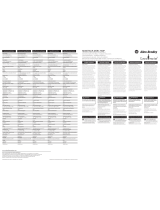
Catalog Number Explanation
Position Number
1-3 45-78 9 10111213141516
20A B 2P2 A 3 A Y Y N N C 0
abcdefghi jkl
a
Drive
Code Type
20A PowerFlex 70
b
Voltage Rating
Code Voltage Ph.
B 240V ac 3
C 400V ac 3
D 480V ac 3
E 600V ac 3
c
ND Output Rating for Voltage Rating
Examples:
Code Amps kW (Hp)
2P2 2.2 0.37 (0.5)
022 22 5.5 (7.5)
e
HIM
Code Interface Module
0 Blank Cover
3 Full Numeric LCD
5 Prog. Only LCD
8
Wireless Interface Module -
IP66, NEMA/UL Type 4X/12
Only
g
Brake IGBT
Code w/Brake IGBT
seYY
h
Internal Brake Resistor
Code w/Resistor
seYY
oNN
l
Feedback
Code Feedback
N NA - Standard Control
0
No Feedback - Enhanced
Control
1
5V/12V Encoder w/Enhanced
Control
j
Comm Slot
Code Version
B BACnet
C ControlNet (Coax)
D DeviceNet
E EtherNet/IP
OIRR
S RS485 DF1
N None
d
Enclosure
Code Enclosure
A
Panel Mount - IP 20, NEMA/UL
Type 1
C
Wall/Machine Mount = IP66,
NEMA/UL Type 4X/12 for
indoor use only
F
Flange Mount - Front Chassis =
IP 20, NEMA/UL Type 1; Rear
Heatsink = IP66, NEMA/UL
Type 4X/12 for indoor/outdoor
use
G
Wall/Machine Mount - IP54,
NEMA/UL Type 12
L
Flange Mount with Conformal
Coat
M
Panel Mount with Conformal
Coat
Only available on Frame E.
f
Documentation
Code Type
A Manual
N No Manual
i
Emission Class
Code Rating
A
Filtered
A & B Frames (Optional)
C, D, & E Frames (Standard)
N
Not Filtered
A & B Frames (Optional)
C, D, & E Frames
600V Frames A through D available only
without filter (Cat. Code N). 600V Frame E
available only with filter (Cat. Code A).
Increases size to Frame B.
k
Control & I/O
Code Control Safe-Off
N Standard N/A
C Enhanced No
G
Enhanced Yes
Not available as factory installed option for
600V ratings.
Step 1 Read the General Precautions
!
ATTENTION: Only qualified personnel familiar with adjustable
frequency AC drives and associated machinery should plan or
implement the installation, start-up and subsequent maintenance of the
system. Failure to comply may result in personal injury and/or
equipment damage.

Publication 20A-IN009C-EN-P
PowerFlex® 70 Adjustable Frequency AC Drive Installation Instructions 5
Personal Safety
Product Safety
!
ATTENTION: To avoid an electric shock hazard, verify that the
voltage on the bus capacitors has discharged before performing any
work on the drive. Measure the DC bus voltage at the +DC terminal of
the Power Terminal Block and the -DC test point (refer to page 13
for
location). The voltage must be zero.
!
ATTENTION: Risk of injury or equipment damage exists. DPI or
SCANport host products must not be directly connected together via
1202 cables. Unpredictable behavior can result if two or more devices
are connected in this manner.
!
ATTENTION: The drive start/stop/enable control circuitry includes
solid state components. If hazards due to accidental contact with
moving machinery or unintentional flow of liquid, gas or solids exist,
an additional hardwired stop circuit may be required to remove the AC
line to the drive. An auxiliary braking method may be required.
!
ATTENTION: An incorrectly applied or installed drive can result in
component damage or a reduction in product life. Wiring or application
errors, such as, undersizing the motor, incorrect or inadequate AC
supply, or excessive ambient temperatures may result in malfunction of
the system.
!
ATTENTION: This drive contains ESD (Electrostatic Discharge)
sensitive parts and assemblies. Static control precautions are required
when installing, testing, servicing or repairing this assembly.
Component damage may result if ESD control procedures are not
followed. If you are not familiar with static control procedures,
reference Guarding Against Electrostatic Damage, publication
8000-4.5.2 or any other applicable ESD protection handbook.
!
ATTENTION: Configuring an analog input for 0-20 mA operation
and driving it from a voltage source could cause component damage.
Verify proper configuration prior to applying input signals.
!
ATTENTION: A contactor or other device that routinely disconnects
and reapplies the AC line to the drive to start and stop the motor can
cause drive hardware damage. The drive is designed to use control input
signals that will start and stop the motor. If an input device is used,
operation must not exceed one cycle per minute or drive damage will
occur.

Publication 20A-IN009C-EN-P
6 PowerFlex® 70 Adjustable Frequency AC Drive Installation Instructions
Output Contactor Precaution
!
ATTENTION: The “adjust freq” portion of the bus regulator function
is extremely useful for preventing nuisance overvoltage faults resulting
from aggressive decelerations, overhauling loads, and eccentric loads. It
forces the output frequency to be greater than commanded frequency
while the drive’s bus voltage is increasing towards levels that would
otherwise cause a fault; however, it can also cause either of the
following two conditions to occur.
1. Fast positive changes in input voltage (more than a 10% increase
within 6 minutes) can cause uncommanded positive speed changes;
however an “OverSpeed Limit” fault will occur if the speed reaches
[Max Speed] + [Overspeed Limit]. If this condition is unacceptable,
action should be taken to 1) limit supply voltages within the
specification of the drive and, 2) limit fast positive input voltage
changes to less than 10%. Without taking such actions, if this operation
is unacceptable, the “adjust freq” portion of the bus regulator function
must be disabled (see parameters 161 and 162).
2. Actual deceleration times can be longer than commanded
deceleration times; however, a “Decel Inhibit” fault is generated if the
drive stops decelerating altogether. If this condition is unacceptable, the
“adjust freq” portion of the bus regulator must be disabled (see
parameters 161 and 162). In addition, installing a properly sized
dynamic brake resistor will provide equal or better performance in most
cases.
Note: These faults are not instantaneous and have shown test results
that take between 2 and 12 seconds to occur.
!
ATTENTION: To guard against drive damage when using output
contactors, the following information must be read and understood.
One or more output contactors may be installed between the drive and
motor(s) for the purpose of disconnecting or isolating certain motors/
loads. If a contactor is opened while the drive is operating, power will
be removed from the respective motor, but the drive will continue to
produce voltage at the output terminals. In addition, reconnecting a
motor to an active drive (by closing the contactor) could produce
excessive current that may cause the drive to fault. If any of these
conditions are determined to be undesirable or unsafe, an auxiliary
contact on the output contactor should be wired to a drive digital input
that is programmed as “Enable.” This will cause the drive to execute a
coast-to-stop (cease output) whenever an output contactor is opened.

Publication 20A-IN009C-EN-P
PowerFlex® 70 Adjustable Frequency AC Drive Installation Instructions 7
CE Conformity
(1)
Conformity with the Low Voltage (LV) Directive and Electromagnetic
Compatibility (EMC) Directive has been demonstrated using
harmonized European Norm (EN) standards published in the Official
Journal of the European Communities. PowerFlex Drives comply with
the EN standards listed below when installed according to the User and
Reference Manuals.
CE Declarations of Conformity are available online at:
www.ab.com/certification/ce/docs
Low Voltage Directive (2006/95/EC)
• EN50178 Electronic equipment for use in power installations.
EMC Directive (89/336/EEC)
• EN61800-3 Adjustable speed electrical power drive systems Part 3:
EMC product standard including specific test methods.
General Notes
• Some drives are equipped with an adhesive label on the top of the
drive. If the adhesive label is removed from the top of the drive, the
drive must be installed in an enclosure with side openings less than
12.5 mm (0.5 in) and top openings less than 1.0 mm (0.04 in) to
maintain compliance with the LV Directive.
• The motor cable should be kept as short as possible in order to avoid
electromagnetic emission as well as capacitive currents.
• Use of line filters in ungrounded systems is not recommended.
• PowerFlex drives may cause radio interference if used in a
residential or domestic environment. The installer is required to take
measures to prevent interference, in addition to the essential
requirements for CE compliance listed below, if necessary.
• Conformity of the drive with CE EMC requirements does not
guarantee an entire machine or installation complies with CE EMC
requirements. Many factors can influence total machine/installation
compliance.
• PowerFlex drives can generate conducted low frequency
disturbances (harmonic emissions) on the AC supply system. More
information regarding harmonic emissions can be found in the
PowerFlex Reference Manual, publication PFLEX-RM004.
EMC Instructions
(1) CE Certification testing has not been completed for 600 Volt class drives.

Publication 20A-IN009C-EN-P
8 PowerFlex® 70 Adjustable Frequency AC Drive Installation Instructions
Essential Requirements for CE Compliance
Conditions 1…6 listed below must be satisfied for PowerFlex drives to
meet the requirements of EN61800-3.
1. Standard PowerFlex 70 CE compatible Drive.
2. Review important precautions/attention statements throughout this
manual before installing drive.
3. Grounding as described in Chapter 1 of the User Manual, publication
20A-UM001.
4. Output power, control (I/O) and signal wiring must be braided,
shielded cable with a coverage of 75% or better, metal conduit or
equivalent attenuation.
5. All shielded cables should terminate with the proper shielded
connector.
6. Conditions in Table A.
Table A PowerFlex 70 EN61800-3 EMC Compatibility
Frame(s)
Drive Description
Second Environment
First Environment
Restricted
Distribution
Restrict Motor
Cable to
40 m (131 ft)
Internal
Filter
Option
External
Filter
Input
Ferrite
(1)
A
Drive Only ✔✔
See PowerFlex
Reference Manual
with any Comm Option ✔✔
with Remote I/O ✔✔✔
B
Drive Only ✔✔
with any Comm Option ✔✔
with Remote I/O ✔✔ ✔
C,
D,
E
Drive Only ✔
with any Comm Option ✔
with Remote I/O ✔✔
(1) Input cables through a Ferrite Core (Frames A, B and C Fair-Rite #2643102002 or equivalent,
Frames D and E Fair-Rite #2643251002 or equivalent).

Publication 20A-IN009C-EN-P
PowerFlex® 70 Adjustable Frequency AC Drive Installation Instructions 9
Minimum Mounting Clearances
Specified vertical clearance requirements are
intended to be from drive to drive. Other objects
can occupy this space; however, airflow must not
be reduced and inlet air temperature must not
exceed the product specification.
Maximum Surrounding Air Temperature
Important: Some drives are equipped with an adhesive label on the top
of the chassis. Removing the adhesive label from the drive
changes the NEMA/UL enclosure rating from Type 1
Enclosed to Open Type.
Step 2 Mount the Drive – Minimum Requirements
Enclosure Rating Temperature Range
Open Type, IP 20, NEMA/UL Type 1 & Flange Mount 0…50 °C (32…22 °F)
IP54, IP 66 & NEMA/UL Type 4X/12 0…40 °C (32…104 °F)
76.2 mm
(3.0 in)
76.2 mm
(3.0 in)

Publication 20A-IN009C-EN-P
10 PowerFlex® 70 Adjustable Frequency AC Drive Installation Instructions
Table B PowerFlex 70 Frames
Dimensions
Output Power Frame Size
kW
ND (HD)
HP
ND (HD)
208…240V AC Input 400…480V AC Input 600V AC Input
Not
(1)
Filtered
(2)
Filtered
IP66
(4X/12)
Not
(1)
Filtered
(2)
Filtered
IP66
(4X/12)
Not
(1)
Filtered
(2)
Filtered
IP66
(4X/12)
0.37 (0.25) 0.5 (0.33) A B B A B B A – B
0.75 (0.55) 1 (0.75) A B B A B B A – B
1.5 (1.1)2 (1.5)BBBABBA–B
2.2 (1.5)3 (2)BBBBBBB–B
4 (3)5 (3)–CDBBBB– B
5.5 (4) 7.5 (5) – D D – C D C – D
7.5 (5.5) 10 (7.5) – D D – C D C – D
11 (7.5) 15 (10) – D D – D D D – D
15 (11) 20 (15) – E E – D D D – D
18.5 (15) 25 (20) – E E – D D D – D
22 (18.5) 30 (25) – – – – D D D – D
30 (22) 40 (30) – – – – E E – E E
37 (30) 50 (40) – – – – E E – E E
(1) Not Filtered indicated if Position 13 of the Catalog Number = N.
(2) Filtered indicated if Position 13 of the Catalog Number = A.
A
E
B
D
F
C
B
AC
D E
IP20/66 (NEMA/UL Type 1/4X/12) Flange Mount
Frame
Dimension Dimensions are in millimeters and (inches)
Weight
(1)
kg (lb)ABCDEF
IP20 / NEMA Type 1
A 122.4 (4.82) 225.7 (8.89) 179.8 (7.08) 94.2 (3.71) 211.6 (8.33) 5.8 (0.23) 2.71 (6.0)
B 171.7 (6.76) 234.6 (9.24) 179.8 (7.08) 122.7 (4.83) 220.2 (8.67) 5.8 (0.23) 3.60 (7.9)
C 185.0 (7.28) 300.0 (11.81) 179.8 (7.08) 137.6 (5.42) 285.6 (11.25) 5.8 (0.23) 6.89 (15.2)
D 219.9 (8.66) 350.0 (13.78) 179.8 (7.08) 169.0 (6.65) 335.6 (13.21) 5.8 (0.23) 9.25 (20.4)
E 280.3 (11.04) 555.8 (21.88) 207.1 (8.15) 200.0 (7.87) 491.0 (19.33) 6.9 (0.27) 18.60 (41.0)
IP66 / NEMA Type 4X/12
B 171.7 (6.76) 239.8 (9.44) 203.3 (8.00) 122.7 (4.83) 220.2 (8.67) 5.8 (0.23) 3.61 (8.0)
D 219.9 (8.66) 350.0 (13.78) 210.7 (8.29) 169.0 (6.65) 335.6 (13.21) 5.8 (0.23) 9.13 (20.1)
E 280.3 (11.04) 555.8 (21.88) 219.8 (8.65) 200.0 (7.87) 491.0 (19.33) 6.9 (0.27) 18.60 (41.0)
Flange Mount
A 156.0 (6.14) 225.8 (8.89) 178.6 (7.03) 123.0 (4.84) 55.6 (2.19) – 2.71 (6.0)
B 205.2 (8.08) 234.6 (9.24) 178.6 (7.03) 123.0 (4.84) 55.6 (2.19) – 3.60 (7.9)
C 219.0 (8.62) 300.0 (11.81) 178.6 (7.03) 123.0 (4.84) 55.6 (2.19) – 6.89 (15.2)
D 248.4 (9.78) 350.0 (13.78) 178.6 (7.03) 123.0 (4.84) 55.6 (2.19) – 9.25 (20.4)
E 280.3 (11.04) 555.8 (21.88) 207.1 (8.15) 117.2 (4.61) 89.9 (3.54) – 18.60 (41.0)
(1) Weights include Human Interface Module (HIM).

Publication 20A-IN009C-EN-P
PowerFlex® 70 Adjustable Frequency AC Drive Installation Instructions 11
Input Power Conditioning
Certain events on the power system supplying a drive can cause
component damage or shortened product life. These conditions are
divided into 2 basic categories:
1. All drives
– The power system has power factor correction capacitors
switched in and out of the system, either by the user or by the
power company.
– The power source has intermittent voltage spikes in excess of
6000 volts. These spikes could be caused by other equipment on
the line or by events such as lightning strikes.
– The power source has frequent interruptions.
2. 5 HP or Less Drives (in addition to “1
” above)
– The nearest supply transformer is larger than 100 kVA or the
available short circuit (fault) current is greater than 100,000 A.
– The impedance in front of the drive is less than 0.5%.
Step 3 Wire the Drive – Wire Recommendations
Type Wire Type(s) Description
Min. Insulation
Rating
Power
(1)(2)
Standard 600V, 90 °C (194 °F)
XHHW2/RHW-2
Anixter
B209500-B209507, Belden
29501-29507, or
equivalent
• Four tinned copper
conductors with XLPE
insulation.
• Copper braid/aluminum foil
combination shield and
tinned copper drain wire.
• PVC jacket.
Signal
(1) (3) (4)
Standard
Analog I/O
Belden 8760/9460(or
equiv.)
0.750 mm
2
(18AWG), twisted
pair, 100% shield with drain.
300V,
75…90 °C
(167…194 °F)
Belden 8770(or equiv.) 0.750 mm
2
(18AWG), 3
cond., shielded for remote pot
only.
Digital I/O
(1) (3) (4)
Shielded Multi-conductor shielded
cable such as Belden
8770(or equiv.)
0.750 mm
2
(18AWG), 3
conductor, shielded.
300V,
60 °C (140 °F)
(1) Control and signal wires should be separated from power wires by at least 0.3 meters (1 foot).
(2) The use of shielded wire for AC input power may not be necessary but is always recommended.
(3) If the wires are short and contained within a cabinet which has no sensitive circuits, the use of
shielded wire may not be necessary, but is always recommended.
(4) I/O terminals labeled “(–)” or “Common” are not referenced to earth ground and are designed to
greatly reduce common mode interference. Grounding these terminals can cause signal noise.

Publication 20A-IN009C-EN-P
12 PowerFlex® 70 Adjustable Frequency AC Drive Installation Instructions
If any or all of these conditions exist, it is recommended that the user
install a minimum amount of impedance between the drive and the
source. This impedance could come from the supply transformer itself,
the cable between the transformer and drive or an additional transformer
or reactor. The impedance can be calculated using the information
supplied in the Wiring and Grounding Guidelines for Pulse Width
Modulated (PWM) AC Drives, publication DRIVES-IN001.
Single-Phase Input Power
The PowerFlex 70 drive is typically used with a three-phase input
supply. The drive has been listed by U.L. to operate on single-phase
input power. Single-phase operation provides 50% of the three-phase
rated current. Refer to Table F
through Table H.
Generator Input Power
Contact Allen-Bradley Drives Technical Support for details on how to
properly power a drive using generator power.
Terminal Block Specifications
Name Frame Description
Wire Size Range
(1)
Torque
Maximum Minimum Maximum Recommended
Power Terminal
Block
A, B, C Input power and
motor connections
4.0 mm
2
(10 AWG)
0.3 mm
2
(22 AWG)
1.1 N•m
(10 lb•in)
0.8 N•m
(7 lb•in)
D Input power and
motor connections
10.0 mm
2
(6 AWG)
0.8 mm
2
(18 AWG)
1.7 N•m
(15 lb•in)
1.4 N•m
(12 lb•in)
E Input power and
motor connections
25.0 mm
2
(3 AWG)
2.5 mm
2
(14 AWG)
2.71 N•m
(24 lb•in)
2.71 N•m
(24 lb•in)
I/O Terminal
Block
All Signal & control
connections
1.5 mm
2
(16 AWG)
0.05 mm
2
(30 AWG)
0.55 N•m
(4.9 lb•in)
0.5 N•m
(4.4 lb•in)
SHLD Terminal All Terminating point
for wiring shields
— — 1.6 N•m
(14 lb•in)
1.6 N•m
(14 lb•in)
(1) Maximum/minimum sizes that the terminal block will accept - these are not recommendations.

Publication 20A-IN009C-EN-P
PowerFlex® 70 Adjustable Frequency AC Drive Installation Instructions 13
Figure 1 Frame A, B, C, D Power Terminal Block and DC Bus Test Points
Figure 2 Frame E Power Terminal Block
Figure 3 Power Input Terminals on Frame B with Internal RFI Filter Option
Terminal Description Notes
RR (L1)
3-Phase AC Line Input Power
For 1-Phase Input, connect to any two terminals.
SS (L2)
TT (L3)
BR1 DC Brake DB Resistor Connection - Important: Do not
connect both an internal and external DB resistor at
the same time. This may violate the minimum
allowed DB resistance and cause drive damage.
BR2 DC Brake
U U (T1) To Motor
V V (T2) To Motor
W W (T3) To Motor
PE PE Ground
PE PE Ground
-DC DC Bus (–)
➊ Test point on Frames A, B, C, and D located to
the left or right of the Power Terminal Block.
Frame E has a dedicated terminal.
+DC DC Bus (+)
L1
R
L2
S
L3
T
BR1
+DC
BR2
BRK
T1
U
T2
V
T3
W
PE PE
-DC
-DC
➊
L1
R
L2
S
L3
T
+DC –DC BR1 BR2 T1
U
T2
V
T3
W
PEPE
M6 M6
L1
R
L2
S
L3
T
BR1
+DC
BR2
BRK
T1
U
T2
V
T3
W
PE PE
-DC
-DC
L1
R
L2
S
L3
T

Publication 20A-IN009C-EN-P
14 PowerFlex® 70 Adjustable Frequency AC Drive Installation Instructions
The tables on the following pages provide drive ratings (including
continuous, 1 minute and 3 second) and recommended AC line input
fuse and circuit breaker information. Both types of short circuit
protection are acceptable for UL and IEC requirements. Sizes listed are
the recommended sizes based on 40 °C and the U.S. N.E.C.
Other
country, state or local codes may require different ratings.
Fusing
If fuses are chosen as the desired protection method, refer to the
recommended types listed below. If available amp ratings do not match
the tables provided, the closest fuse rating that exceeds the drive rating
should be chosen.
• IEC – BS88 (British Standard) Parts 1 & 2
(1)
, EN60269-1, Parts 1 &
2, type gG or equivalent should be used.
• UL – UL Class CC, T, RK1 or J should be used.
Circuit Breakers
The “non-fuse” listings in the following tables include both circuit
breakers (inverse time or instantaneous trip) and 140M Self-Protecting
Motor Starters. If one of these is chosen as the desired protection
method, the following requirements apply.
• IEC and UL – Both types of devices are acceptable for IEC and UL
installations.
Power & Ground Wiring
U (T1)
V (T2)
W (T3)
R (L1)
S (L2)
T (L3)
PE
SHLD
Drive, Fuse & Circuit Breaker Ratings
(1) Typical designations include, but may not be limited to the following; Parts 1 & 2: AC,
AD, BC, BD, CD, DD, ED, EFS, EF, FF, FG, GF, GG, GH.

Publication 20A-IN009C-EN-P
PowerFlex® 70 Adjustable Frequency AC Drive Installation Instructions 15
Table C 208/240 Volt AC Three-Phase Input Drive Ratings and Input Protection Devices (See page 17 for Notes)
Drive
Catalog
Number
Frame
(1)
HP
Rating
Input
Ratings Output Amps
Dual
Element Time
Delay Fuse
Non-Time
Delay Fuse
Circuit
Breaker
(4)
Motor
Circuit
Protector
(6)
140M Motor Protector with Adjustable Current Range
(7)
(8)
ND HD Amps kVA Cont. 1 Min. 3 Sec. Min.
(2)
Max.
(3)
Min.
(2)
Max.
(3)
Max.
(5)
Max.
(5)
Available Catalog Numbers
(9)
208 Volt AC Input
20AB2P2 A 0.5 0.33 2.9 1.1 2.5 2.7 3.7 6 6 6 10 15 7 140M-C2E-B40 140M-D8E-B40 – –
20AB4P2 A 1 0.75 5.6 2 4.8 5.5 7.4 10 10 10 17.5 15 7 140M-C2E-B63 140M-D8E-B63 – –
20AB6P8 B 2 1.5 10 3.6 7.8 10.3 13.8 15 15 15 30 30 15 140M-C2E-C10 140M-D8E-C10 140M-F8E-C10 –
20AB9P6 B 3 2 14 5.1 11 12.1 16.5 20 25 20 40 40 30 140M-C2E-C16 140M-D8E-C16 140M-F8E-C16 –
20AB015 C 5 3 16 5.8 17.5 19.2 26.6 20 35 20 70 70 30 140M-C2E-C20 140M-D8E-C20 140M-F8E-C20 –
20AB022 D 7.5 5 23.3 8.3 25.3 27.8 37.9 30 50 30 100 100 30 140M-C2E-C25 140M-D8E-C25 140M-F8E-C25 140-CMN-2500
20AB028 D 10 7.5 29.8 10.7 32.2 37.9 50.6 40 70 40 125 125 50 – – 140M-F8E-C32 140-CMN-4000
20AB042 D 15 10 39.8 14.3 43 55.5 74 60 100 60 175 175 70 – – 140M-F8E-C45 140-CMN-6300
20AB054 E 20 15 57.5 20.7 62.1 72.4 96.6 80 125 80 200 200 100 – – – 140-CMN-6300
20AB070 E 25 20 72.3 26.0 78.2 93.1 124 90 175 90 300 300 100 – – – 140-CMN-9000
240 Volt AC Input
20AB2P2 A 0.5 0.33 2.5 1.1 2.2 2.4 3.3 3 4.5 3 8 15 3 140M-C2E-B25 140M-D8E-B25 – –
20AB4P2 A 1 0.75 4.8 2 4.2 4.8 6.4 6 9 6 15 15 7 140M-C2E-B63 140M-D8E-B63 – –
20AB6P8 B 2 1.5 8.7 3.6 6.8 9 12 15 15 15 25 25 15 140M-C2E-C10 140M-D8E-C10 140M-F8E-C10 –
20AB9P6 B 3 2 12.2 5.1 9.6 10.6 14.4 20 20 20 35 35 15 140M-C2E-C16 140M-D8E-C16 140M-F8E-C16 –
20AB015 C 5 3 13.9 5.8 15.3 17.4 23.2 20 30 20 60 60 30 140M-C2E-C16 140M-D8E-C16 140M-F8E-C16 –
20AB022 D 7.5 5 19.9 8.3 22 24.4 33 25 45 25 80 80 30 140M-C2E-C25 140M-D8E-C25 140M-F8E-C25 140-CMN-2500
20AB028 D 10 7.5 25.7 10.7 28 33 44 35 60 35 110 110 50 – – 140M-F8E-C32 140-CMN-4000
20AB042 D 15 10 38.7 16.1 42 46.2 63 50 90 50 150 150 50 – – 140M-F8E-C45 140-CMN-6300
20AB054 E 20 15 49.8 20.7 54 63 84 60 100 60 200 200 100 – – – 140-CMN-6300
20AB070 E 25 20 64.5 26.8 70 81 108 90 150 90 275 275 100 – – – 140-CMN-9000

Publication 20A-IN009C-EN-P
16 PowerFlex® 70 Adjustable Frequency AC Drive Installation Instructions
Table D 400/480 Volt AC Three-Phase Input Drive Ratings and Input Protection Devices (See page 17 for Notes).
Drive
Catalog
Number
Frame
(1)
kW (400V)
HP (480V)
Rating
Input
Ratings Output Amps
Dual
Element Time
Delay Fuse
Non-Time
Delay Fuse
Circuit
Breaker
(4)
Motor
Circuit
Protector
(6)
140M Motor Protector with Adjustable Current Range
(7)
(8)
ND HD Amps kVA Cont. 1 Min. 3 Sec. Min.
(2)
Max.
(3)
Min.
(2)
Max.
(3)
Max.
(5)
Max.
(5)
Available Catalog Numbers
(9)
400 Volt AC Input
20AC1P3 A 0.37 0.25 1.6 1.1 1.3 1.4 1.9 3 3 3 5 15 3 140M-C2E-B16 – – –
20AC2P1 A 0.75 0.55 2.5 1.8 2.1 2.4 3.2 4 6 4 8 15 7 140M-C2E-B25 140M-D8E-B25 – –
20AC3P5 A 1.5 1.1 4.3 3 3.5 4.5 6 6 6 6 12 15 7 140M-C2E-B63 140M-D8E-B63 – –
20AC5P0 B 2.2 1.5 6.5 4.5 5 5.5 7.5 10 10 10 20 20 15 140M-C2E-C10 140M-D8E-C10 140M-F8E-C10 –
20AC8P7 B 4 3 11.3 7.8 8.7 9.9 13.2 15 17.5 15 30 30 15 140M-C2E-C16 140M-D8E-C16 140M-F8E-C16 –
20AC011 C 5.5 4 10.5 7.6 11.5 13 17.4 15 25 15 45 40 15 140M-C2E-C16 140M-D8E-C16 140M-F8E-C16 –
20AC015 C 7.5 5.5 145.1 10.4 15.4 17.2 23.1 20 30 20 60 60 20 140M-C2E-C16 140M-D8E-C16 140M-F8E-C16 –
20AC022 D 11 7.5 21.9 15.2 22 24.2 33 30 45 30 80 80 30 140M-C2E-C25 140M-D8E-C25 140M-F8E-C25 140-CMN-2500
20AC030 D 15 11 30.3 21 30 33 45 40 60 40 120 120 50 – – 140M-F8E-C32 140-CMN-4000
20AC037 D 18.5 15 35 24.3 37 45 60 50 80 50 125 140 50 – – 140M-F8E-C45 140-CMN-4000
20AC043 D 22 18.5 40.7 28.2 43 56 74 60 90 60 150 160 70 – – – 140-CMN-6300
20AC060 E 30 22 56.8 39.3 60 66 90 80 125 80 225 240 80 – – – 140-CMN-6300
20AC072 E 37 30 68.9 47.8 72 90 120 90 150 90 250 280 100 – – – 140-CMN-9000
480 Volt AC Input
20AD1P1 A 0.5 0.33 1.3 1.1 1.1 1.2 1.6 3 3 3 4 15 3 140M-C2E-B16 – – –
20AD2P1 A 1 0.75 2.4 2 2.1 2.4 3.2 3 6 3 8 15 3 140M-C2E-B25 140M-D8E-B25 – –
20AD3P4 A 2 1.5 3.8 3.2 3.4 4.5 6 6 6 6 12 15 7 140M-C2E-B40 140M-D8E-B40 – –
20AD5P0 B 3 2 5.6 4.7 5 5.5 7.5 10 10 10 20 20 15 140M-C2E-B63 140M-D8E-B63 – –
20AD8P0 B 5 3 9.8 8.4 8 8.8 12 15 15 15 30 30 15 140M-C2E-C10 140M-D8E-C10 140M-F8E-C10 –
20AD011 C 7.5 5 9.4 7.9 11 12.1 16.5 15 20 15 40 40 15 140M-C2E-C16 140M-D8E-C16 140M-F8E-C16 –
20AD014 C 10 7.5 12.4 10.4 14 16.5 22 20 30 20 50 50 20 140M-C2E-C16 140M-D8E-C16 140M-F8E-C16 –
20AD022 D 15 10 19.9 16.6 22 24.2 33 25 45 25 80 80 30 140M-C2E-C25 140M-D8E-C25 140M-F8E-C25 –
20AD027 D 20 15 24.8 20.6 27 33 44 35 60 35 100 100 50 – – 140M-F8E-C32 140-CMN-2500
20AD034 D 25 20 31.2 25.9 34 40.5 54 40 70 40 125 125 50 – – 140M-F8E-C45 140-CMN-4000
20AD040 D 30 25 36.7 30.5 40 51 68 50 90 50 150 150 50 – – 140M-F8E-C45 140-CMN-4000
20AD052 E 40 30 47.7 39.7 52 60 80 60 110 60 200 200 70 – – – 140-CMN-6300
20AD065 E 50 40 59.6 49.6 65 78 104 80 125 80 250 250 100 – – – 140-CMN-9000

Publication 20A-IN009C-EN-P
PowerFlex® 70 Adjustable Frequency AC Drive Installation Instructions 17
Table E 600 Volt AC Three-Phase Input Drive Ratings and Input Protection Devices
Drive
Catalog
Number
Frame
(1)
(1) For IP 66 (NEMA/UL Type 4X/12) enclosures, drives listed as Frame A increase to Frame B and drives listed as Frame C increase to Frame D.
HP
Rating
Input
Ratings Output Amps
Dual
Element Time
Delay Fuse
Non-Time
Delay Fuse
Circuit
Breaker
(4)
(4) Circuit Breaker - inverse time breaker. For US NEC, minimum size is 125% of motor FLA. Ratings shown are maximum.
Motor
Circuit
Protector
(6)
(6) Motor Circuit Protector - instantaneous trip circuit breaker. For US NEC, minimum size is 125% of motor FLA. Ratings shown are maximum.
140M Motor Protector with Adjustable Current Range
(7)
(8)
(7) Bulletin 140M with adjustable current range should have the current trip set to the minimum range that the device will not trip.
(8) Manual Self-Protected (Type E) Combination Motor Controller, UL listed for 208 Wye or Delta, 240 Wye or Delta, 480Y/277 or 600Y/347. Not UL listed for use on 480V or
600V Delta/Delta systems in single motor applications.
ND HD Amps kVA Cont. 1 Min. 3 Sec. Min.
(2)
(2) Minimum protection device size is the lowest rated device that supplies maximum protection without nuisance tripping.
Max.
(3)
(3) Maximum protection device size is the highest rated device that supplies drive protection. For US NEC, minimum size is 125% of motor FLA. Ratings shown are maximum.
Min.
(2)
Max.
(3)
Max.
(5)
(5) Maximum allowable rating by US NEC. Exact size must be chosen for each installation.
Max.
(5)
Available Catalog Numbers
(9)
(9) The AIC ratings of the Bulletin 140M Motor Protector may vary. See publication 140M-SG001B-EN-P.
600 Volt AC Input
20AE0P9 A 0.5 0.33 1.3 1.3 0.9 1.1 1.4 3 3 3 3.5 15 3 140M-C2E-B16 – – –
20AE1P7 A 1 0.75 1.9 2 1.7 2 2.6 3 6 3 6 15 3 140M-C2E-B25 140M-D8E-B25 – –
20AE2P7 A 2 1.5 3 3.1 2.7 3.6 4.8 4 6 4 10 15 7 140M-C2E-B40 140M-D8E-B40 – –
20AE3P9 B 3 2 4.4 4.5 3.9 4.3 5.9 6 8 6 15 15 7 140M-C2E-B63 140M-D8E-B63 – –
20AE6P1 B 5 3 7.5 7.8 6.1 6.7 9.2 10 12 10 20 20 15 140M-C2E-C10 140M-D8E-C10 140M-F8E-C10 –
20AE9P0 C 7.5 5 7.7 8 9 9.9 13.5 10 20 10 35 35 15 140M-C2E-C10 140M-D8E-C10 140M-F8E-C10 –
20AE011 C 10 7.5 9.8 10.1 11 13.5 18 15 20 15 40 40 15 140M-C2E-C16 140M-D8E-C16 140M-F8E-C16 –
20AE017 D 15 10 15.3 15.9 17 18.7 25.5 20 35 20 60 60 30 140M-C2E-C20 140M-D8E-C20 140M-F8E-C20 –
20AE022 D 20 15 20 20.8 22 25.5 34 25 45 25 80 80 30 140M-C2E-C25 140M-D8E-C25 140M-F8E-C25 140-CMN-2500
20AE027 D 25 20 24.8 25.7 27 33 44 35 60 35 100 100 50 – – 140M-F8E-C25 140-CMN-2500
20AE032 D 30 25 29.4 30.5 32 40.5 54 40 70 40 125 125 50 – – 140M-F8E-C32 140-CMN-4000
20AE041 E 40 30 37.6 39.1 41 48 64 50 90 50 150 150 100 – – 140M-F8E-C45 140-CMN-4000
20AE052 E 50 40 47.7 49.6 52 61.5 82 60 110 60 200 200 100 – – – 140-CMN-6300

Publication 20A-IN009C-EN-P
18 PowerFlex® 70 Adjustable Frequency AC Drive Installation Instructions
Table F 208/240 Volt AC Single-Phase Input Drive Ratings and Input Protection Devices (See page 20 for Notes)
Drive
Catalog
Number
Frame
(1)
HP
Rating
Input
Ratings Output Amps
Dual
Element Time
Delay Fuse
Non-Time
Delay Fuse
Circuit
Breaker
(4)
Motor
Circuit
Protector
(6)
140M Motor Protector with Adjustable Current Range
(7)
(8)
ND HD Amps kVA Cont. 1 Min. 3 Sec. Min.
(2)
Max.
(3)
Min.
(2)
Max.
(3)
Max.
(5)
Max.
(5)
Available Catalog Numbers
(9)
208 Volt AC Input
20AB2P2 A 0.5 0.33 2.9 0.6 1.3 1.6 1.9 6 6 6 10 15 7 140M-C2E-B40 140M-D8E-B40 – –
20AB4P2 A 1 0.75 5.6 1 2.4 2.8 3.7 10 10 10 17.5 15 7 140M-C2E-B63 140M-D8E-B63 – –
20AB6P8 B 2 1.5 10 1.8 3.9 5.2 6.9 15 15 15 30 30 15 140M-C2E-C10 140M-D8E-C10 140M-F8E-C10 –
20AB9P6 B 3 2 14 2.6 5.5 6.1 8.3 20 25 20 40 40 30 140M-C2E-C16 140M-D8E-C16 140M-F8E-C16 –
20AB015 C 5 3 16 2.9 8.6 9.6 13.3 20 35 20 70 70 30 140M-C2E-C20 140M-D8E-C20 140M-F8E-C20 –
20AB022 D 7.5 5 23.3 4.2 12.7 13.9 19.0 30 50 30 100 100 30 140M-C2E-C25 140M-D8E-C25 140M-F8E-C25 140-CMN-2500
20AB028 D 10 7.5 29.8 5.4 16.1 19 25.3 40 70 40 125 125 50 – – 140M-F8E-C32 140-CMN-4000
20AB042 D 15 10 39.8 7.2 21.5 27.8 37 60 100 60 175 175 70 – – 140M-F8E-C45 140-CMN-6300
20AB054 E 20 15 57.5 10.4 31.1 36.2 48.3 80 125 80 200 200 100 – – – 140-CMN-6300
20AB070 E 25 20 72.3 13.0 39.1 46.6 62 90 175 90 300 300 100 – – – 140-CMN-9000
240 Volt AC Input
20AB2P2 A 0.5 0.33 2.5 0.6 1.1 1.2 1.7 3 4.5 3 8 15 3 140M-C2E-B25 140M-D8E-B25 – –
20AB4P2 A 1 0.75 4.8 1 2.1 2.4 3.2 6 9 6 15 15 7 140M-C2E-B63 140M-D8E-B63 – –
20AB6P8 B 2 1.5 8.7 1.8 3.4 4.5 6 15 15 15 25 25 15 140M-C2E-C10 140M-D8E-C10 140M-F8E-C10 –
20AB9P6 B 3 2 12.2 2.6 4.8 5.3 7.2 20 20 20 35 35 15 140M-C2E-C16 140M-D8E-C16 140M-F8E-C16 –
20AB015 C 5 3 13.9 2.9 7.7 8.7 11.6 20 30 20 60 60 30 140M-C2E-C16 140M-D8E-C16 140M-F8E-C16 –
20AB022 D 7.5 5 19.9 4.2 11 12.2 16.5 25 45 25 80 80 30 140M-C2E-C25 140M-D8E-C25 140M-F8E-C25 140-CMN-2500
20AB028 D 10 7.5 25.7 5.4 14 16.5 22 35 60 35 110 110 50 – – 140M-F8E-C32 140-CMN-4000
20AB042 D 15 10 38.7 8.1 21 23.1 31.5 50 90 50 150 150 50 – – 140M-F8E-C45 140-CMN-6300
20AB054 E 20 15 49.8 10.4 27 31.5 42 60 100 60 200 200 100 – – – 140-CMN-6300
20AB070 E 25 20 64.5 13.4 35 40.5 54 90 150 90 275 275 100 – – – 140-CMN-9000

Publication 20A-IN009C-EN-P
PowerFlex® 70 Adjustable Frequency AC Drive Installation Instructions 19
Table G 400/480 Volt AC Single-Phase Input Drive Ratings and Input Protection Devices (See page 20 for Notes).
Drive
Catalog
Number
Frame
(1)
kW (400V)
HP (480V)
Rating
Input
Ratings Output Amps
Dual
Element Time
Delay Fuse
Non-Time
Delay Fuse
Circuit
Breaker
(4)
Motor
Circuit
Protector
(6)
140M Motor Protector with Adjustable Current Range
(7)
(8)
ND HD Amps kVA Cont. 1 Min. 3 Sec. Min.
(2)
Max.
(3)
Min.
(2)
Max.
(3)
Max.
(5)
Max.
(5)
Available Catalog Numbers
(9)
400 Volt AC Input
20AC1P3 A 0.37 0.25 1.6 0.6 0.7 0.7 1.0 3 3 3 5 15 3 140M-C2E-B16 – – –
20AC2P1 A 0.75 0.55 2.5 0.9 1.1 1.2 1.6 4 6 4 8 15 7 140M-C2E-B25 140M-D8E-B25 – –
20AC3P5 A 1.5 1.1 4.3 1.5 1.8 2.3 3 6 6 6 12 15 7 140M-C2E-B63 140M-D8E-B63 – –
20AC5P0 B 2.2 1.5 6.5 2.3 2.5 2.8 3.8 10 10 10 20 20 15 140M-C2E-C10 140M-D8E-C10 140M-F8E-C10 –
20AC8P7 B 4 3 11.3 3.9 4.4 5.0 6.6 15 17.5 15 30 30 15 140M-C2E-C16 140M-D8E-C16 140M-F8E-C16 –
20AC011 C 5.5 4 11 3.8 5.8 6.5 8.7 15 25 15 45 40 15 140M-C2E-C16 140M-D8E-C16 140M-F8E-C16 –
20AC015 C 7.5 5.5 15.1 5.2 7.7 8.6 11.6 20 30 20 60 60 20 140M-C2E-C16 140M-D8E-C16 140M-F8E-C16 –
20AC022 D 11 7.5 21.9 7.6 11 12.1 16.5 30 45 30 80 80 30 140M-C2E-C25 140M-D8E-C25 140M-F8E-C25 140-CMN-2500
20AC030 D 15 11 30.3 10.5 15 16.5 22.5 40 60 40 120 120 50 – – 140M-F8E-C32 140-CMN-4000
20AC037 D 18.5 15 35 12.2 18.5 22.5 30 50 80 50 125 140 50 – – 140M-F8E-C45 140-CMN-4000
20AC043 D 22 18.5 40.7 14.1 21.5 28 37 60 90 60 150 160 70 – – – 140-CMN-6300
20AC060 E 30 22 56.8 19.7 30 33 45 80 125 80 225 240 80 – – – 140-CMN-6300
20AC072 E 37 30 68.9 23.9 36 45 60 90 150 90 250 280 100 – – – 140-CMN-9000
480 Volt AC Input
20AD1P1 A 0.5 0.33 1.3 0.6 0.6 0.6 0.8 3 3 3 4 15 3 140M-C2E-B16 – – –
20AD2P1 A 1 0.75 2.4 1 1.1 1.2 1.6 3 6 3 8 15 3 140M-C2E-B25 140M-D8E-B25 – –
20AD3P4 A 2 1.5 3.8 1.6 1.7 2.3 3 6 6 6 12 15 7 140M-C2E-B40 140M-D8E-B40 – –
20AD5P0 B 3 2 5.6 2.4 2.5 2.6 3.8 10 10 10 20 20 15 140M-C2E-B63 140M-D8E-B63 – –
20AD8P0 B 5 3 9.8 4.2 4 4.4 6 15 15 15 30 30 15 140M-C2E-C10 140M-D8E-C10 140M-F8E-C10 –
20AD011 C 7.5 5 9.5 4 5.5 6.1 8.3 15 20 15 40 40 15 140M-C2E-C16 140M-D8E-C16 140M-F8E-C16 –
20AD014 C 10 7.5 12.5 5.2 7 8.3 11 20 30 20 50 50 20 140M-C2E-C16 140M-D8E-C16 140M-F8E-C16 –
20AD022 D 15 10 19.9 8.3 11 12.1 16.5 25 45 25 80 80 30 140M-C2E-C25 140M-D8E-C25 140M-F8E-C25 –
20AD027 D 20 15 24.8 10.3 13.5 16.5 22 35 60 35 100 100 50 – – 140M-F8E-C32 140-CMN-2500
20AD034 D 25 20 31.2 13 17 20.3 27 40 70 40 125 125 50 – – 140M-F8E-C45 140-CMN-4000
20AD040 D 30 25 36.7 19.9 20 25.5 34 50 90 50 150 150 50 – – 140M-F8E-C45 140-CMN-4000
20AD052 E 40 30 47.7 12.8 26 30 40 60 110 60 200 200 70 – – – 140-CMN-6300
20AD065 E 50 40 59.6 24.8 32.5 39 52 80 125 80 250 250 100 – – – 140-CMN-9000

Publication 20A-IN009C-EN-P
20 PowerFlex® 70 Adjustable Frequency AC Drive Installation Instructions
Table H 600 Volt AC Single-Phase Input Drive Ratings and Input Protection Devices
Drive
Catalog
Number
Frame
(1)
(1) For IP 66 (NEMA/UL Type 4X/12) enclosures, drives listed as Frame A increase to Frame B and drives listed as Frame C increase to Frame D.
HP
Rating
Input
Ratings Output Amps
Dual
Element Time
Delay Fuse
Non-Time
Delay Fuse
Circuit
Breaker
(4)
(4) Circuit Breaker - inverse time breaker. For US NEC, minimum size is 125% of motor FLA. Ratings shown are maximum.
Motor
Circuit
Protector
(6)
(6) Motor Circuit Protector - instantaneous trip circuit breaker. For US NEC, minimum size is 125% of motor FLA. Ratings shown are maximum.
140M Motor Protector with Adjustable Current Range
(7)
(8)
(7) Bulletin 140M with adjustable current range should have the current trip set to the minimum range that the device will not trip.
(8) Manual Self-Protected (Type E) Combination Motor Controller, UL listed for 208 Wye or Delta, 240 Wye or Delta, 480Y/277 or 600Y/347. Not UL listed for use on 480V or
600V Delta/Delta systems in single motor applications.
ND HD Amps kVA Cont. 1 Min. 3 Sec. Min.
(2)
(2) Minimum protection device size is the lowest rated device that supplies maximum protection without nuisance tripping.
Max.
(3)
(3) Maximum protection device size is the highest rated device that supplies drive protection. For US NEC, minimum size is 125% of motor FLA. Ratings shown are maximum.
Min.
(2)
Max.
(3)
Max.
(5)
(5) Maximum allowable rating by US NEC. Exact size must be chosen for each installation.
Max.
(5)
Available Catalog Numbers
(9)
(9) The AIC ratings of the Bulletin 140M Motor Protector may vary. See publication 140M-SG001B-EN-P.
600 Volt AC Input
20AE0P9 A 0.5 0.33 1.3 0.7 0.5 0.6 0.7 3 3 3 3.5 15 3 140M-C2E-B16 – – –
20AE1P7 A 1 0.75 1.9 1 0.9 1 1.3 3 6 3 6 15 3 140M-C2E-B25 140M-D8E-B25 – –
20AE2P7 A 2 1.5 3 1.6 1.4 1.8 2.4 4 6 4 10 15 7 140M-C2E-B40 140M-D8E-B40 – –
20AE3P9 B 3 2 4.4 2.3 2 2.2 3 6 8 6 15 15 7 140M-C2E-B63 140M-D8E-B63 – –
20AE6P1 B 5 3 7.5 3.9 3.1 3.4 4.6 10 12 10 20 20 15 140M-C2E-C10 140M-D8E-C10 140M-F8E-C10 –
20AE9P0 C 7.5 5 7.7 4 4.5 5 6.8 10 20 10 35 35 15 140M-C2E-C10 140M-D8E-C10 140M-F8E-C10 –
20AE011 C 10 7.5 9.8 5.1 5.5 6.8 9 15 20 15 40 40 15 140M-C2E-C16 140M-D8E-C16 140M-F8E-C16 –
20AE017 D 15 10 15.3 8 8.5 9.4 12.8 20 35 20 60 60 30 140M-C2E-C20 140M-D8E-C20 140M-F8E-C20 –
20AE022 D 20 15 20 10.4 11 12.8 17 25 45 25 80 80 30 140M-C2E-C25 140M-D8E-C25 140M-F8E-C25 140-CMN-2500
20AE027 D 25 20 24.8 12.9 13.5 16.5 22 35 60 35 100 100 50 – – 140M-F8E-C25 140-CMN-2500
20AE032 D 30 25 29.4 15.3 16 20.3 27 40 70 40 125 125 50 – – 140M-F8E-C32 140-CMN-4000
20AE041 E 40 30 37.6 19.6 20.5 24 32 50 90 50 150 150 100 – – 140M-F8E-C45 140-CMN-4000
20AE052 E 50 40 47.7 24.8 26 30.8 41 60 110 60 200 200 100 – – – 140-CMN-6300
/