
R-25AM
SHARP CORPORATION
SERVICE MANUAL
S0315R25AMH//
COMMERCIAL
MICROWAVE OVEN
MODEL
R-25AM
In interests of user-safety the oven should be restored to its
original condition and only parts identical to those specified
should be used.
TABLE OF CONTENTS
Page
CAUTION, MICROWAVE RADIATION....................................................................... INSIDE FRONT COVER
WARNING ..........................................................................................................................................................1
SERVICING ...................................................................................................................................................... 2
PRODUCT SPECIFICATIONS ......................................................................................................................... 5
GENERAL INFORMATION ................................................................................................................................5
APPEARANCE VIEW ....................................................................................................................................... 6
OPERATION SEQUENCE................................................................................................................................ 7
FUNCTION OF IMPORTANT COMPONENTS ................................................................................................ 9
TROUBLESHOOTING GUIDE ........................................................................................................................10
TEST PROCEDURE ........................................................................................................................................12
TOUCH CONTROL PANEL ASSEMBLY ........................................................................................................ 18
COMPONENT REPLACEMENT AND ADJUSTMENT PROCEDURE ........................................................... 25
MICROWAVE MEASUREMENT .................................................................................................................... 32
TEST DATA AT A GLANCE ........................................................................................................................... 33
WIRING DIAGRAM ......................................................................................................................................... 34
PICTORIAL DIAGRAM ................................................................................................................................... 36
CONTROL PANEL CIRCUIT ........................................................................................................................... 37
PRINTED WIRING BOARD .............................................................................................................................38
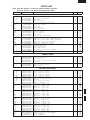
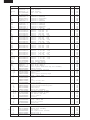
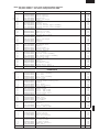
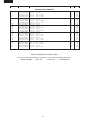
PARTS LIST ................................................................................................................................................... 39
2100W/R-25AM

R-25AM
CAUTION
MICROWAVE RADIATION
Personnel should not be exposed to the microwave energy which may radiate from the
magnetron or other microwave generating devices if it is improperly used or connected.
All input and output microwave connections, waveguides, flanges and gaskets must be
secured.
Never operate the device without a microwave energy absorbing load attached.
Never look into an open waveguide or antenna while the device is energized.
VARNING
MICKROVAGSSTRALING
Personal får inte utsättas för mikrovågsenergi som kan ustrala från magnetronen eller
andre mikrovågsalstrande anordningar om dessa är felanslutna eller används på fel sätt.
Alla in-och utgångsanslutningar för mikrovågor, vagledare, flänsar och packningar måste
vara fast anslutna.
Mikrovågsgeneratorn får inte arbeta utan att absorberande belastning är ansluten. Titta
aldrig in i ën öppen vågledare eller antenn när mikrovågsgeneratorn är påkopplad eller
laddad.
VAROITUS
MIKROAALTOSÄTELYÄ
Käyttäjä ei saa joutua alttiiksi mikroaaltoenergialle, jota voi säteillä magnetronista tai
muusta mikroaaltoja kehittävästä laitteesta, jos sitä käytetään tai jos se kytketään väärin.
Kaikkien mikroaaltoliitäntöjen sekä syöttö-että ulostulopuolella, aaltoputkien laippojen ja
tiivisteiden tulee olla varmistettuja.
Mikroaaltouunnia ei koskaan saa käyttää ilman kuormaa jossa mikroaaltoenergiaa kuluu.
Avoimeen aaltoputkeen tai antenniin ei koskaan saa katsoa virran ollessa kytkettynä.
ADVARSEL
MIKROBØLGESTRÅLING
Personell må ikke utsettes for mikrobølge-energi som kan utståles fra magnetronen eller
andre mikrobølge-generende deler dersom apparatet feilbetjenes eller blir feiltikoplet.
Alle inn-og ut-tilkoplinger i forbindelse med mikrobølge-strålingen, bølgeledere, flenser og
tetningsringer/pakninger må festes ordentlig.
Aldri bruk apparatet med mindre en mikrobålge-absorberende last er plassert i
ovnsrommet.
Aldri se direkte inn i en åpen bølgeleder eller antenne imens apparatet er strømførende.
ADVARSEL
MIKROBØLGEBESTRÄLING
Man bør ikke udsætte sig for mikrobølgebestråling fra magnetronen eller andre
mikrobølgefrembringende anordninger, hvilket kan ske hvis apparatet er forkert tilsluttet
eller bruges forkert. Alle mikrobølgeindgange og-udgange, bølgeledere, flanger og
tætningsstrimler må være forsvarligt udført.
Anvend aldrig ovnen uden en mikrobølgesabsorberende anordning. Se aldrig ind i en
åben bølgeleder eller antenne, mens ovnen er i brug.

1
R-25AM
SERVICE MANUAL
COMMERCIAL MICROWAVE OVEN
R-25AM
GENERAL IMPORTANT INFORMATION
This Manual has been prepared to provide Sharp Corp. Service
engineers with Operation and Service Information.
It is recommended that service engineers carefully study the entire
text of this manual, so they will be qualified to render satisfactory
customer service.
CAUTION
MICROWAVE RADIATION
DO NOT BECOME EXPOSED TO RADIATION FROM THE
MICROWAVE GENERATOR OR OTHER PARTS THAT CON-
DUCT MICROWAVE ENERGY.
WARNING
Note: The parts marked "*" are used in voltage more
than 250V. (Parts List)
Anm: Delar märket med "*" har en spänning
överstigande 250V.
Huom: Huolto-ohjeeseen merkitty "tähdella" osat joissa
jännite on yli 250 V.
Bemerk: Deler som er merket "asterisk" er utsatt for
spenninger over 250V til jord.
Bemærk: "Dele mærket med stjerne benyttes med højere
spænding end 250 volt.
WARNING
Never operate the oven until the following points are ensured.
(A) The door is tightly closed.
(B) The door brackets and hinges are not defective.
(C) The door packing is not damaged.
(D) The door is not deformed or warped.
(E) There is not any other visible damage with the oven.
Servicing and repair work must be carried out only by trained service
engineers.
All the parts marked "*" on parts list are used at voltage more than
250V.
Removal of the outer wrap gives access to potential above 250V.
All the parts marked "∆" on the parts list may cause undue
microwave exposure, by themselves, or when they are damaged,
loosened or removed.
SHARP CORPORATION
OSAKA, JAPAN
SERVICING
PRODUCT SPECIFICATIONS
GENERAL INFORMATION
APPEARANCE VIEW
OPERATING SEQUENCE
FUNCTION OF IMPORTANT
COMPONENTS
TROUBLESHOOTING GUIDE
AND TEST PROCEDURE
TOUCH CONTROL PANEL
COMPONENT REPLACEMENT
AND ADJUSTMENT PROCEDURE
MICROWAVE MEASUREMENT
TEST DATA AT A GLANCE
WIRING DIAGRAM
PARTS LIST

2
R-25AM
REMEMBER TO CHECK 3D
1) Disconnect the supply.
2) Door opened, and wedged open.
3) Discharge two high voltage capacitors.
WARNING: AGAINST THE CHARGE OF THE TWO
HIGH-VOLTAGE CAPACITORS
The two high-voltage capacitors remains charged about 60
seconds after the oven has been switched off. Wait for 60
seconds and then short-circuit the connection of the two
high-voltage capacitors (that is, of the connecting lead of the
high-voltage rectifier) against the chassis with the use of an
insulated screwdriver.
Sharp recommend that wherever possible fault-finding is
carried out with the supply disconnected. It may in, some
cases, be necessary to connect the supply after the outer
case has been removed, in this event carry out 3D checks and
then disconnect the leads to the primary of the two High
voltage transformers. Ensure that these leads remain isolated
from other components and the oven chassis. (Use insulation
tape if necessary.) When the testing is completed carry out 3D
checks and reconnect the leads to the primary of the two High
voltage transformers.
SERVICING
WARNING TO SERVICE PERSONNEL
GB Microwave ovens contain circuitry capable of producing very high voltage and current, contact with following parts will result
in electrocution. High voltage capacitor, High voltage transformer, Magnetron, High voltage rectifier assembly, High voltage
fuses, High voltage harness.
REMEMBER TO CHECK 4R
1) Reconnect all leads removed from components during
testing.
2) Replace the outer case (cabinet).
3) Reconnect the supply.
4) Run the oven. Check all functions.
Microwave ovens should not be run empty. To test for the
presence of microwave energy within a cavity, place a cup of
cold water on the oven turntable, close the door and set the
power to HIGH and set the microwave timer for one (1) minute.
When the one minute has elapsed (timer at zero) carefully
check that the water is now hot. If the water remains cold carry
out
3D checks and re-examine the connections to the compo-
nent being tested.
When all service work is completed, and the oven is fully
assembled, the microwave power output should be checked and
a microwave leakage test should be carried out.
NL Magnetronovens bevatten circuits die een zeer hoge spanning en stroom kunnen voortbrengen. Contact met de
volgende onderdelen kan elektrocutie tot gevolg hebben.
Hoogspanningscondensator, hoogspanningstransformator, magnetron, hoogspanningsgelijkrichter, hoogspannings
kabelboom.
VERGEET DE VOLGENDE 3 STAPPEN NIET
1) Haal de stekker uit het stopcontact.
2) Open de deur en zorg ervoor dat hij niet dicht kan vallen.
3) Ontlaad de hoogspanningscondensator.
PAS OP VOOR DE ELECTRISCHE LADING VAN DE
HOOGSPANNINGSCONDENSATOR
De hoogspanningscondensator blijft nog ongeveer 60
seconden lang opgeladen, nadat de oven is uitgeschakeld.
Wacht 60 seconden voordat u de verbinding van de
hoogspannings-condensator (m.a.w. de verbindingsdraad
van de hoogspanningsgelijkrichter) met een geïsoleerde
schroevedraaier kortsluit tegen het chassis.
Sharp beveelt ten sterkste aan dat, voor zover mogelijk,
defecten worden opgespoord wanneer de stekker uit het
stopcontact is gehaald. Soms is het nodig om de stroomtoevoer
weer tot stand te brengen nadat de buitenmantel verwijderd
is. Herhaal dan de bovengenoemde 3 stappen en haal de
electrische draden uit de primaire zijde van de
vermogenstransformator. Zorg ervoor dat deze draden
geïsoleerd blijven van andere elementen en van het chassis
van de oven. (Gebruik zo nodig isolatieband.) Wanneer de
test is uitgevoerd, herhaalt u de bovenstaande 3 stappen en
verbindt u de electrische draden weer aan de primaire zijde
van de vermogenstransformator.
VERGEET DE VOLGENDE 4 STAPPEN NIET
1) Sluit de draden weer aan diezijn losgehaald voor de test.
2) Plaats de buitenmantel weer om het toestel heen (kabinet).
3) Stop de stekker weer in het stopcontact.
4) Zet de oven aan. Controleer alle functies.
Magnetronovens mogen niet leeg aangezet worden. Om te
controleren of er microgolf-energie binnen de oven wordt
geproduceerd, plaatst u een mok met koud water op de
draaitafel van de oven, sluit de deur, zet de oven op HIGH en
stelt de klok van de magnetron in op twee (2) minuten. Wanneer
de twee minuten voorbij zijn (klok staat op nul), controleert u
voorzichtig of het water heet is. Indien het water nog steeds
koud is, herhaalt u de allereerste drie stappen en controleer
nogmaals de aansluitingen naar de geteste onderdelen.
Wanneer alle reparaties zijn uitgevoerd en de oven weer in
elkaar is gezet, moet de het magnetronvermogen worden
gecontroleerd en moet worden gecontroleerd of er geen
microgolflekkage is.

3
R-25AM
E Los hornos de microondas contienen circuitos eléctricos capaces de producir voltajes de alta tensión y descargas
eléctricas. Para evitar el riesgo de electrocución, absténgase de tocar los siguientes componentes: condensador de alta
tensión, transformador de alta tensión, magnetrón, dispositivo del rectificador de alta tensión y arnés de alta tensión.
RECUERDE LA COMPROBACION 3D
1) Desconecte la alimentación.
2) Deje la puerta abierta y calzada.
3) Descargue el condensador de alto voltaje.
ADVERTENCIA SOBRE LA CARGA DEL
CONDENSADOR DE ALTO VOLTAJE
El condensador de alto voltaje permanece cargado unos
60 segundos después de haber apagado el horno. Espere
60 segundos y luego ponga en cortocircuito la conexión del
condensador de alto voltaje (esto es, del conductor de
conexión del rectificador de alto voltaje) al chasis con un
destornillador de mango aislado.
Se recomienda encarecidamente que siempre que sea
posible la localización de fallos se realice con la alimentación
desconectada. Puede ser que en algunos casos sea
necesario conectar la alimentación después de haber retirado
la carcasa exterior. En este caso, realice las comprobaciones
3D y luego desconecte los conductores del primario del
transformador de alimentación. Asegúrese de que estos
conductores permanezcan aislados de otros componentes y
del chasis del horno. (Use cinta aislante si es necesario).
Cuando termine la prueba efectúe las comprobaciones 3D y
reconecte los conductores al primario del transformador de
alimentación.
RECUERDE LA COMPROBACION 4C
1) Conecte todos los componentes desconectados de los
componentes durante la prueba.
2) Coloque la carcasa exterior (cabina).
3) Conecte la alimentación.
4) Compruebe todas sus funciones despues de poner en
marcha el horno.
Los hornos de microondas no deben funcionar vacíos. Para
comprobar la presencia de energía de microondas dentro de
una cavidad, coloque una taza de agua fría en el plato giratorio
del horno, cierre la puerta y ponga la potencia en HIGH (alta)
y coloque el temporizador en dos (2) minutos. Cuando
transcurran los dos minutos (temporizador a cero) compruebe
cuidadosamente que el agua se ha calentado. Si el agua
permaneciese fría, efectúe las comprobaciones 3D y vuelva a
examinar las conexiones de los componentes que han sido
probados.
Cuando haya terminado la intervención en el equipo y el horno
haya sido ensamblado de nuevo completamente, deberá
comprobar la potencia de salida de microondas y realizar una
prueba de fugas de microondas.
SV Mikrovågsugnar innehåller kretsar som producerar mycket höga spänningar och strömmar.
Kontakt med följande komponenter kan leda till dödsfall:
Högspänningskondensator, transformator, magnetron, högspännings likriktare, högspännings kablage.
KOM IHÅG ATT KONTROLLERA 3 STEG
1) Koppla från strömkällan.
2) Öppna dörren på glänt.
3) Ladda ur högspänningskondensatorn.
VARNING FÖR LADDNINGEN I
HÖGSPÄNNINGSKONDENSATORN
Högspänningskondensatorn är laddad i 60 sekunder efter
det att ugnen stängts av. Vänta 60 sekunder och korislut
sedan kondensatoms anslutning (dvs anslutningen till
högspänningslikriktaren) till chassiet med hjälp av en isolerad
skruvmejsel.
Sharp rekommenderar att felsökning sker med strömmen
fränkopplad. Ibland kan det var nödvändigt att koppla på
strömmen efter det att höljet avlägsnats, utför da 3 Steg
kontrollen och koppla sedan från ledarna till transformatorns
primärsida. Se till att ledarna är isolerade från andra
komponenter och chassiet. (Använd isoleringsband om det
behövs). När Du testat färdigt utför Du 3 Steg kontrollen och
ansluter ledningarna till transformatorns primärsida igen.
KOM IHÅG ATT KONTROLLERA 4 STEG
1) Anslut alla ledningar som använts vid testning
2) Sätt tillbaka ytterhöljet.
3) Anslut strömkällan på nytt.
4) Sätt på ugnen. Kontrollera alla funktioner.
Mikrovågsugnar får inte användas tomma. Kontrollera
mikrovågsstrålningen i olika delar av ugnen genom att placera
en kopp med kallt vatten på ugnens tallrik, stäng dörren, ställ
in HIGH och ställ in 2 minuter på timern. När två minuter har gått
(timem visar 0) kontrollerar du om vattnet är varmt. Om vattnet
fortfarande är kallt utför Du 3 steg kontroller och kontrollerar
anslutningarna till varje enskild komponent på nytt.
När all service är klar och ugnen ihopskruvad skall ugnens
uteffekt och eventuellt mikrovågsläckage kontrolleras.

4
R-25AM
II forni a microonde contengono un circuito elettrico in grado di generare tensioni e correnti estremamente elevate.
L’eventuale contatto con i seguenti componenti può causare la folgorazione:
condensatore ad alta tensione; trasformatore ad alta tensione; magnetron; rettificatore alta tensione; cablaggio ad
alta tensione.
TRE OPERAZIONI IMPORTANTI PER
INCOMINCIARE
1) Scollegare l'alimentazione elettrica.
2) Verificare che la porta sia bloccata in posizione
aperta.
3) Scaricare il condensatore ad alta tensione.
ATTENZIONE AL CONDENSATORE AD ALTA
TENSIONE: PUO ESSERE CARICO
Il condensatore ad alta tensione rimane carico per circa
60 secondi dopo lo spegnimento del forno. Occorre quindi
spettare 60 secondi prima di cortocircuitare, utilizzando
un cacciavite con impugnatura isolata, il collegamento
del condensatore ad alta tensione (cioè del conduttore
di collegamento del raddrizzatore ad alta tensione) sul
telaio del forno.
Sharp raccomanda, nei limiti del possibile, che la ricerca
dei guasti avvenga in assenza di alimentazione elettrica.
In alcuni casi tuttavia, può essere necessario alimentare
l'apparecchio dopo aver rimosso la scatola esterna. In
questo caso eseguire i tre controlli sopra citati e quindi
scollegare i connettori dal primario del trasformatore.
Assicurarsi che tali connettori non vengano a contatto con
altri componenti, ne con il telaio del forno (fare uso, se
necessario, di nastro isolante). Al termine dell'intervento,
eseguire nuovamente i tre controlli e ricollegare i conduttori
al primario del trasformatore.
QUATTRO VERIFICHE IMPORTANTI DA NON
DIMENTICARE
1) Ricollegare tutti i conduttori staccati dai vari componenti
durante l'intervento.
2) Rimontare la scatola esterna.
3) Ripristinare l'alimentazione elettrica.
4) Rimettere in funzione il forno. Controllare tutte le funzioni.
I forni a microonde non devono mai funzionare a vuoto. Per
verificare la presenza di energia da microonde all'interno
di una cavitá, mettere una tazza di acqua fredda sul piatto
rotante del forno, chiudere la porta, regolare la potenza su
HIGH ed impostate il temporizzatore su due (2) minuti.
Trascorsi i due minuti (temporizzatore a zero), controllare
accuratamente che ora l'acqua sia calda. Se l'acqua è
rimasta fredda, eseguire i tre controlli iniziali e verificare
nuovamente i collegamenti del componente in questione.
Dopo aver portato a termine le operazioni di manutenzione
e rimontato il forno, è necessario controllare la potenza delle
microonde emesse ed eseguire un test per verificare che
non vi sia alcuna dispersione.

5
R-25AM
GENERAL INFORMATION
WARNING
THIS APPLIANCE MUST BE EARTHED
IMPORTANT
THE WIRES IN THIS MAINS LEAD ARE COLOURED IN ACCORDANCE WITH THE FOLLOWING CODE:
GREEN-AND-YELLOW : EARTH
BLUE : NEUTRAL
BROWN : LIVE
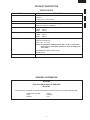
PRODUCT DESCRIPTION
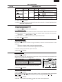
SPECIFICATION
ITEM DESCRIPTION
Power Requirements 230 Volts
50 Hertz
Single phase, 3 wire earthed
Power Comsumption
3.15 kW Approx. 15 A
Power Output
2100 W nominal of RF microwave energy (measured by method of IEC 60705)
Operating frequency 2450 MHz
Case Dimensions Width 510mm
Height 335 mm
Depth 470mm
Cooking Cavity Dimensions Width 330 mm
Height 180 mm
Depth 330mm
Control Complement Electronic Timer (0 - 30 minutes)
Microwave Power level
100% 50% 20% 10%
NOTE: The maximum cooking time for 100% or 50% is 15 minutes.
If the time you set exceeds a maximum time, the display will
show "EE9".
MICROWAVE POWER LEVEL buttons
START button
Set Weight Approx. 33 kg

6
R-25AM
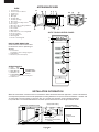
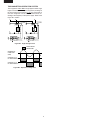
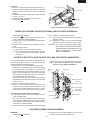
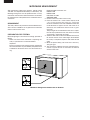
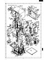
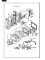
APPEARANCE VIEW
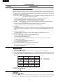
OVEN
1. Control panel
2. Hole for safety door latches
3. Ceramic floor
4. Splash cover
5. Oven light
6. Air intake filter
7. Air intake openings
8. Oven cavity
9. Door seals and sealing surfaces
10. Door hinges
11. Oven door with see-through window
12. Door safety latches
13. Door handle.
14. Outer cabinet
15. Removable cover over oven light bulb
16. Air vent openings
17. Power supply cord
18 Mounting plate
19 Screw for mounting plate
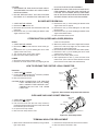
DISPLAY AND INDICATORS
Check indicators after the oven starts
to confirm the oven is operating as
desired.
1. Cook indicator
This indicator shows cooking in progress.
2. Digital display
3. Microwave power level display
OPERATING KEYS
4. HIGH 100%
5. MEDIUM 50%
6. MED LOW 20%
7. DEFROST 10%
8. ELECTRONIC TIMER
Rotate the control to enter cooking time.
9. START button
AUTO TOUCH CONTROL PANEL
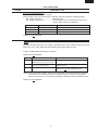
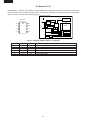
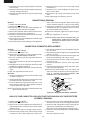
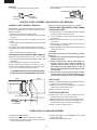
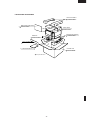
INSTALLATION INFORMATION
When this commercial microwave oven is installed near other commercial electrical appliances, connect a lead wire to
each equivalent potential terminal with equipotential marking between them (insert a lead wire between a washer and
an earth angle, and screw them), as shown in Fig. A-1, to make sure that they are at equivalent potential.
If any lead wire is not connected between them, when person touch them he/she will get a electric shock.
Figure A-1
4
1
5
2
10
3
679
8
11
12
13
17
16
14
15
19
18
COMMERCIAL MICROWAVE OVEN OTHER COMMERCIAL
ELECTRICAL APPLIANCE
Lead wire
Equipotential marking
Earth angle
(Equivalent potential terminal)
Equivalent
potential terminal
Screw
Washer
Lead wire
MICROWAVE
POWER LEVEL
buttons
4
5
6
7
8
9
POWER
%
ON
2
1
3

7
R-25AM
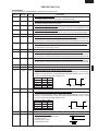
OPERATION SEQUENCE
4. When the cooking time is up, a signal tone is heard and
the relays RY3+RY4 go back to their home position.
The circuits to the high voltage transformers T1+T2.
The relay RY1 remains and oven lamp, blower motor
and antenna motors work for 1 minute.
5. When the door is opened during a cook cycle, the
switches come to the following condition.
CONDITION
DURING DOOR OPEN
SWITCH CONTACT COOKING
(NO COOKING)
Interlock switches COM-NO Closed Open
Monitor switches COM-NC Open Closed
Stop switch COM-NO Closed Open
The circuits to the high voltage transformers T1+T2 are
cut off when the interlock and stop switches
SW1+SW2+SW5 are made open. The blower motor BM,
antenna motors and oven lamp remains on even if the
oven door is opened after the cooking cycle has been
interrupted, because the relay RY1 stays closed. Shown
in the display is the remaining time, but the program is
cancelled if the oven is not started within 1 minute.
6. MONITOR SWITCH CIRCUIT
The monitor switches SW3+SW4 are mechanically
controlled by oven door, and monitors the operation of
the interlock switches SW1+SW2.
6-1. When the oven door is opened during or after the
cycle of a cooking program, the interlock switches
SW1+SW2 and stop switches SW5 must open their
contacts first. After that the contacts (COM-NC) of the
monitor switches SW3+SW4 can be closed.
6-2. When the oven door is closed, the contacts (COM-
NC) of the monitor switches SW3+SW4 must be
opened first. After that the contacts (COM-NO) of the
interlock switches SW1+SW2 and stop switch SW5
must be closed.
6-3. When the oven door is opened and the contacts of the
interlock switch SW1 (or SW2) remain closed, re-
mains closed, the fuse F1 F10A (or F2 F10A) will
blow, because the monitor switch SW3 (or SW4) is
closed and a short circuit is caused.
MICROWAVE VARIABLE COOKING
When the microwave oven is preset for variable cooking
power, the line voltage is supplied to the high voltage
transformers T1+T2 intermittently within a 48 second time
base through the contacts of the relays RY3+RY4.
The following levels of microwaves power are given.
Closing the door activates all door interlock switches
(interlock switches and stop switch).
IMPORTANT
When the oven door is closed, the monitor switch contacts
COM-NC must be open. When the microwave oven is
plugged in a wall outlet (230 volts, 50Hz), the line voltage
is supplied to the control unit through the noise filter.
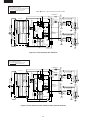
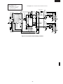
Figure O-1 on page 34
1. The digital display shows . 0
IDLE CONDITION
When the door is opened, the contacts of the interlock
switches SW1+SW2 and stop switch SW5 open, initiating
the following:
Figure O-2 on page 34
1. A signal is input to the control unit energizing the coil of
shut-off relay RY-1.
2. The shut-off relay RY-1 contacts close completing
circuits to turn on the oven lamp, blower motor and
antenna motors.
3. If the door remains open, 60 seconds later the control
unit de-energizes shut-off relay RY-1 turning off the
oven lamp, blower motor and antenna motors.
When the door is closed, the contacts of the interlock switches
SW1+SW2 and stop switch SW5 close. With the closing of the
stop switch SW5 contacts, an additional circuit is provided which
will permit the operation of the oven when one of the touch pads
is depressed. Since the control is enabled through the stop
switch SW5, the door must be closed before the touch pads will
be effective. When the door is closed, a full 60 second IDLE
condition is always provided for selecting and pressing the
desired touch pads. A 60 second IDLE condition will also follow
the end of each cook cycle.
MICROWAVE COOKING CONDITION
Enter a desired cooking time by turning ELECTRONIC
TIMER knob. And then touch START button.
NOTE: The programme is canceled when any buttons
are not touched for more than 3 minutes dur-
ing programming.
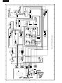
Function sequence Figure O-3 on page 35
CONNECTED COMPONENTS RELAY
Oven lamp/ Blower motor/ Antenna motors RY1
High voltage transformer T1 RY3
High voltage transformer T2 RY4
1. The line voltage is supplied to the primary winding of
the two high voltage transformers. The voltage is
converted to about 3.3 volts A.C. output on the filament
winding and high voltage of approximately 2000 volts
A.C. on the secondary winding.
2. The filament winding voltage (3.3 volts) heats the
magnetron filament and the high voltage (2000 volts) is
sent to the voltage doubling circuit, where it is doubled
to negative voltage of approximately 4000 volts D.C..
3. The 2450 MHz microwave energy produced in the magnet-
ron generates a wave length of 12.24 cm. This energy is
channelled through the waveguide (transport channel) into
the oven cavity, where the food is placed to be cooked.
NOTE: The ON/OFF time ratio does not exactly corre-
spond to the percentage of microwave power,
because approx. 3 seconds are needed for heat-
ing up the magnetron filament.
48 sec. ON
10%
26 sec. ON
50%
12 sec. ON
20%
8 sec. ON
10%

8
R-25AM
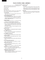
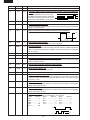
TWO MAGNETRON OPERATION SYSTEM
Two magnetrons MG1+MG2 are equipped in order to get
higher microwave power output. The primary windings of
the high voltage transformers T1+T2 are connected so
that each magnetron can be oscillated alternatively ac-
cording to the frequency of the power supply. Refer to the
Figure B-1 and B-2.
Figure B-1. High Voltage Circuit
Figure B-2. Operation of Magnetron
T1: HIGH VOLTAGE
TRANSFORMER
H. V. RECTIFIER
C1: H.V. CAPACITOR
MG1: MAGNETRON (UPPER)
(REAR)
H. V. RECTIFIER
H. V. FUSE H. V. FUSE
C2: H.V. CAPACITOR
MG2: MAGNETRON (LOWER)
T2: HIGH VOLTAGE
TRANSFORMER
(FRONT)
COMMERCIAL
FREQUENCY
(50HZ)
POWER OUTPUT
BY MAGNETRON T1
POWER OUTPUT
BY MAGNETRON T2
OPERATION OF
MAGNETRON

9
R-25AM
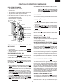
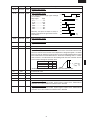
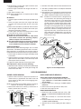
DOOR OPEN MECHANISM
1. The door release lever is pulled.
2. The upper latch head is lifted up by the linked door
release lever.
3. The head lever is lifted up by the door release lever.
4. The joint lever is lifted up by the head lever.
5. The lower latch head is lifted up by the joint lever.
6. Now both latch heads are lifted up, so they can be
released from the latch hook.
7. Now the door can be opened.
Figure D-1. Door Open Mechanism
INTERLOCK SWITCHES SW1, SW2 AND STOP
SWITCH SW5
1. When the oven door is closed, the contacts COM-NO
must be closed.
2. When the oven door is opened, the contacts COM-NO
must be opened.
MONITOR SWITCHES SW3, SW4
The monitor switches SW3, SW4 are activated (the con-
tacts opened) the upper latch head and switch lever A
while the door is closed. The switch SW3 (or SW4) is
intended to render the oven inoperative by means of
blowing the fuse F1 F10A (or F2 F10A) when the contacts
of the interlock switch SW1 (or SW2) fail to open when the
door is opened.
Function
1. When the door is opened, the monitor switches SW3
+SW4 contacts close (to the ON condition) due to their
being normally closed. At this time the interlock switch
SW1+SW2 are in the OFF condition (contacts open)
due to their being normally open contact switches.
2. As the door goes to a closed position, the monitor
switches SW3+SW4 contacts are opened and inter-
lock switch SW1+SW2 contacts are closed (On open-
ing the door, each of these switches operate inversely.)
3. If the door is opened and the interlock switch SW1 (or
SW2) contacts fail to open, the fuse F1 F10A (or F2
F10A) blows simultaneously with closing of the monitor
switch SW3 (or SW4) contacts.
FUNCTION OF IMPORTANT COMPONENTS
CAUTION:BEFORE REPLACING A BLOWN FUSE F1
F10A (OR F2 F10A) TEST THE INTERLOCK
SWITCH SW1 (OR SW2) AND MONITOR
SWITCHE SW3 (OR SW4) FOR PROPER
OPERATION. (REFER TO CHAPTER “TEST
PROCEDURE”).
NOISE FILTER
The noise filter assembly prevents radio frequency inter-
ference that might flow back in the power circuit.
FUSES F1, F2 F10A 250V
1. If the wire harness or electrical components are short-
circuited, this fuse blows to prevent an electric shock or
fire hazard.
2. The fuse F1 F10A (or F2 F10A) also blows when
interlock switch SW1 (or SW2) remains closed with the
oven door open and when the monitor switches SW3
(or SW4) closes.
WEAK POINT F3
If the wire harness or electrical components make a short-
circuit, this weak point F3 blows to prevent an electric
shock or fire hazard.
HIGH VOLTAGE FUSE(S) F4, F5
The high voltage fuse blows when the high voltage rectifier
or the magnetron is shorted.
MAGNETRON TEMPERATURE FUSES TF1, TF2
The temperature fuses TF1, TF2 located on the top of the
upper and lower waveguide, are designed to prevent
damage to the magnetrons MG1, MG2. If an over heated
condition develops in the tube due to blower motor failure,
obstructed air ducts, dirty or blocked air intake, etc., the
circuit to the magnetrons are interrupted. Under normal
operation, the temperature fuses remains closed. How-
ever, when abnormally high temperatures are generated
within the magnetrons, the temperature fuses will open at
150˚C causing the microwave energy to stop. The defec-
tive temperature fuses must be replaced with new rated
ones.
EXHAUST TEMPERATURE FUSE TF3
The temperature fuse TF3, located on the side of the
exhaust duct assembly, is designed to prevent damage to
the oven by fire. If the food load is overcooked, by either
error in cook time or defect in the control unit, the tempera-
ture fuse will open. Under normal operation, the oven
temperature fuse remains closed. However, when abnor-
mally high temperatures are generated within the oven
cavity, the oven temperature fuse will open at 120˚C,
causing the oven to shut down. The defective temperature
fuse must be replaced with new rated one.
EXHAUST OVEN THERMISTOR TH3
The thermistor is a negative temperature coefficient type.
The temperature in the exhaust duct is detected through
the resistance of the thermistor.
If the temperature is high, the control panel will display
“EE7” and the oven will stop to avoid overheating and
Latch head
SW4: Monitor switch
(Oven side)
SW3: Monitor switch
Latch hook
SW1: Interlock switch
SW2: Interlock switch
(Oven side)
SW5: Stop switch
Latch head
Joint lever
Door release
lever
Head lever

10
R-25AM
catching fire.
If the thermistor is open, the control panel will display
"EE6" and the oven will stop.
MAGNETRON THERMISTORS TH1, TH2
The thermistor is a negative temperature coefficient type.
The air temperature around the magnetron is detected
through the resistance of the thermistor.
If the temperature is high, the control panel will display
"EE17" and the oven will stop to protect the lower magn-
etron against overheat.
If the magnetron thermistor is open, the control panel will
display "EE16" and the oven will stop.
If the magnetron thermistor is short, the control panel will
display "EE19" and the oven will stop.
BLOWER MOTOR BM
The blower motor BM drives a blade which draws external
cool air into the oven. This cool air is directed through the
air vanes surrounding the magnetrons and cools the
magnetrons. This air is channelled through the oven cavity
to remove steam and vapours given off from the heating
foods. It is then exhausted through the exhausting air
vents at the oven cavity.
ANTENNA MOTORS SM
The upper and lower antenna motors SM drive stirrer
antennas.
OVEN LAMP OL
The oven cavity light illuminates the interior of the oven so
that food being cooked can be examined visually through the
door window without having to open the door. The oven lamp
is on during the cooking cycle and idle condition.
TROUBLESHOOTING GUIDE
When troubleshooting the microwave oven, it is helpful to follow the Sequence of Operation in performing the checks.
Many of the possible causes of trouble will require that a specific test be performed. These tests are given a procedure
letter which will be found in the “Test Procedure”section.
IMPORTANT: If the oven becomes inoperative because of a blown fuse F1 F10A (or F2 F10A) in the interlock switch
SW1 (or SW2) - monitor switches SW3 (or SW4) , check the interlock switch SW1 (or SW2) and monitor
switches SW3 (or SW4) before replacing the fuse F1 F10A (or F2 F10A).

11
R-25AM
. does not appear on display when power cord is plugged into
wall outlet.
Control panel can not accept buttons or timer in.
Fuse F1 or F2 blows when the door is opened.
Home fuse blows when power cord is plugged into wall outlet.
Weak point F3 blows when power cord is plugged into wall outlet.
Oven lamp, fan motor and antenna motors do not work for 1
minute when the door is opened or after cooking.
Fuse F1 or F2 blows when power cord is plugged into wall outlet.
Oven lamp does not light when door is opened. (Blower and antenna
motors work)
Blower motor does not work when door is opened. (Oven lamp
lights and antenna motors work)
EE 1 (Magnetron MG1 failure)
EE 2 (Magnetron MG2 failure)
EE 3 (Magnetron MG1 and MG2 failure)
EE 6 (Exhaust thermistoropen)
EE 7 (Exhaust air temperature is high)
EE 9 (Exceeded max. heating time)
Oven lamp, blower motor and antenna motors do not work.
Oven lamp does not work.
Blower motor does not work.
Oven does not stop after end of cooking cycle.
Home fuse blows when starting the oven.
Oven goes into cook cycle but shuts down before end of cooking cycle.
It passed more than 1 minute after cooking but oven lamp, blower
motor and stirrer motors do not stop.
EE 16 (Thermistor of magnetron are open.)
EE 17 (Magnetron temperature is high.)
EE 19 (Magnetron thermistor short)
EE 10 (Fault of memory)
Antenna motors do not work.
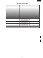
TESTPROCEDURE
POSSIBLE CAUSE
AND
DEFECTIVE PARTS
CONDITION
OFF
CONDITION
ON
CONDITION
PROBLEM
EEP ROM I-2
N SWITCH UNIT
TOUCH CONTROL TRANSFORMER T3
Due to programme lock
Over the max. cooking time
No power at wall outlet
HOME FUSE or BREAKER
Mis adjustment of switches
P FUSE 2.5A
O RELAY RY-4
O RELAY RY-3
O RELAY RY-1
M TOUCH CONTROL PANEL
Opened wire harness
Shorted wire harness
POWER SUPPLY CORD
K NOISE FILTER
OVEN LAMP OR SOCKET
J BLOWER MOTOR BM
J ANTENNA MOTORS SM
I EXHAUST THERMISTOR TH3
I MAGNETRON THERMISTOR (Lower) TH2
I MAGNETRON THERMISTOR (Upper) TH1
L HIGH VOLTAGE FUSE F5
L HIGH VOLTAGE FUSE F4
H EXHAUST TEMPERATURE FUSE TF3
H MAGNETRON TEMPERATURE FUSE TF2
H MAGNETRON TEMPERATURE FUSE TF1
F WEAK POINT F3
G FUSE F10A F2
G FUSE F10A F1
E STOP SWITCH SW5
E MONITOR SWITCH SW4
E MONITOR SWITCH SW3
E INTERLOCK SWITCH SW2
D INTERLOCK SWITCH SW1
D H.V. CAPACITOR C2
D H.V. CAPACITOR C1
H.V. WIRE HARNESS
C H.V. RECTIFIER ASSEMBLY FOR MG2
C H.V. RECTIFIER ASSEMBLY FOR MG1
B HIGH VOLTAGE TRANSFORMER T2 (Rear)
B HIGH VOLTAGE TRANSFORMER T1 (Front)
A MAGNETRON MG2 (Lower)
A MAGNETRON MG1 (Upper)

12
R-25AM
A MAGNETRON TEST
TEST PROCEDURES
PROCEDURE
LETTER COMPONENT TEST
CARRY OUT
3D CHECKS.
Isolate the magnetron from high voltage circuit by removing all leads connected to filament terminal.
To test for an open circuit filament use an ohmmeter to make a continuity test between the magnetron
filament terminals, the meter should show a reading of less than 1 ohm.
To test for short circuit filament to anode condition, connect ohmmeter between one of the filament
terminals and the case of the magnetron (ground). This test should be indicated an infinite resistance.
If a low or zero resistance reading is obtained then the magnetron should be replaced.
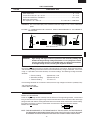
MICROWAVE OUTPUT POWER (1 litre water load)
The following test procedure should be carried out with the microwave oven in a fully assembled
condition (outer case fitted). Microwave output power from the magnetron can be measured by way
of IEC 60705, i.e. it is measured by how much power the water load can absorb. To measure the
microwave output power in the microwave oven, the relation of calorie and watt is used. When P(W)
heating works for t(second), approximately P x t/4.187 calorie is generated. On the other hand, if the
temperature of the water with V(ml) rises ∆T (°C) during this microwave heating period, the calorie of
the water is V x ∆T.
Measuring condition:
1. Container
The water container must be a cylindrical borosilicate glass vessel having a maximum material
thickness of 3 mm and an outside diameter of approximately 190 mm.
2. Temperature of the oven and vessel
The oven and the empty vessel are at ambient temperature prior to the start the test.
3. Temperature of the water
The initial temperature of the water is (10±1)°C.
4. Select the initial and final water temperature so that the maximum difference between the final water
temperature and the ambient temperature is 5°C.
5. Select stirring devices and measuring instruments in order to minimize addition or removal of heat.
6. The graduation of the thermometer must be scaled by 0.1°C at minimum and be an accurate
thermometer.
7. The water load must be (1000±5) g.
8. “t” is measured while the microwave generator is operating at full power. Magnetron filament heat-
up time is not included.
NOTE: The operation time of the microwave oven is “t + 3” sec. (3 sec. is magnetron filament heat-up time.)
Measuring method:
1. Measure the initial temperature of the water before the water is added to the vessel.
(Example: The initial temperature T1 = 11°C)
2. Add the 1 litre water to the vessel.
3. Place the load on the centre of the shelf.
4. Operate the microwave oven at HIGH until the temperature of the water rises by a value ∆ T of
(10 ± 2) K.
5. Stir the water to equalize temperature throughout the vessel.
6. Measure the final water temperature. (Example: The final temperature T2 = 21°C)
7. Calculate the microwave power output P in watts from above formula.
NEVER TOUCH ANY PART IN THE CIRCUIT WITH YOUR HAND OR AN INSULATED TOOL
WHILE THE OVEN IS IN OPERATION.
The formula is as follows;
P x t / 4.187 = V x ∆ T+ 0.55 x mc (T2-T0) P (W) = 4.187 x V x ∆T / t + 0.55 x mc (T2-T0)/t
Our condition for water load is as follows:
Room temperature (T0) ...... around 20°CPower supply Voltage .............. Rated voltage
Water load.....................................1000 g Initial temperature (T1) ...................... 10±1°C
Heating time ................................. 20 sec. Mass of container (mc) ......................... 330 g
T2 ............... Final temperature P = 210 x ∆T+ 0.55 x mc(T2-T0)/20

13
R-25AM
Room temperature ................................................................................................. T0 = 21°C
Initial temperature .................................................................................................. T1 = 11°C
Temperature after (20 + 3) = 23 sec ...................................................................... T2 = 21°C
Temperature difference Cold-Warm...................................................................... ∆T1 = 10˚C
Measured output power
The equation is “P = 210 x ∆T” ................................................ P = 210 x 10°C = 2100 Watts
JUDGMENT: The measured output power should be within the range of ± 15 % of the rated output
power.
CAUTION: 1°C CORRESPONDS TO 210 WATTS. REPEAT MEASUREMENT IF THE POWER IS
INSUFFICIENT.
TEST PROCEDURES
PROCEDURE
LETTER COMPONENT TEST
Heat up for 23 sec.
B HIGH VOLTAGE TRANSFORMER TEST
WARNING: High voltage and large currents are present at the secondary winding and
filament winding of the high voltage transformer. It is very dangerous to work
near this part when the oven is on. NEVER make any voltage measurements
of the high-voltage circuits, including the magnetron filament.
CARRY OUT 3D CHECKS.
Disconnect the leads to the primary winding of the high voltage transformer. Disconnect the filament
and secondary winding connections from the rest of the HV circuitry. Using an ohmmeter, set on a low
range, it is possible to check the continuity of all three windings. The following readings should be
obtained:-
a. Primary winding approximately 1.2 Ω
b. Secondary winding approximately 75 Ω
c. Filament winding less than 1 Ω
If the readings obtained are not stated as above, then the high voltage transformer is probably faulty
and should be replaced.
CARRY OUT 4R CHECKS.
CARRY OUT 3D CHECKS.
Isolate the high voltage rectifier assembly from the HV circuit. The high voltage rectifier can be tested
using an ohmmeter set to its highest range. Connect the ohmmeter across the terminal B+C of the high
voltage rectifier and note the reading obtained. Reverse the meter leads and note this second reading.
The normal resistance is infinite in one direction and more than 100 kΩ in the other direction.
CARRY OUT 4R CHECKS.
NOTE: FOR MEASUREMENT OF THE RESISTANCE OF THE RECTIFIER, THE BATTERIES OF
THE MEASURING INSTRUMENT MUST HAVE A VOLTAGE AT LEAST 6 VOLTS, BECAUSE
OTHERWISE AN INFINITE RESISTANCE MIGHT BE SHOWN IN BOTH DIRECTIONS.
C HIGH VOLTAGE RECTIFIER ASSEMBLY TEST
B
C
HIGH VOLTAGE RECTIFIER
1000g
1000g
1000g
T1˚C
T2˚C

14
R-25AM
F WEAK POINT F3 TEST
CARRY OUT 3D CHECKS.
If the weak point F3 is blown, there could be a shorts or grounds in electrical parts or wire harness.
Check them and replace the defective parts or repair the wire harness.
CARRY OUT 4R CHECKS.
CAUTION: Only replace weak point F3 with the correct value replacement.
If incorrect readings are obtained, make the necessary switch adjustment or replace the switch.
CARRY OUT 4R CHECKS.
G FUSE F1, F2 F10A TEST
CARRY OUT 3D CHECKS.
If the fuse F1 F10A (or F2 F10A) is blown when the door is opened, check the interlock switch SW1
(or SW2) and monitor switch SW3 (or SW4).
If thefuse F1 F10A (or F2 F10A) is blown by incorrect door switching replace the defective switch(s)
and the fuse F1 F10A (or F2 F10A).
CARRY OUT 4R CHECKS.
CAUTION: Only replace fuse F1 F10A (or F2 F10A) with the correct value replacement.
H TEMPERATURE FUSE TF1, TF2, TF3 TEST
TEST PROCEDURES
PROCEDURE
LETTER COMPONENT TEST
E SWITCH TEST
CARRY OUT 3D CHECKS.
Isolate the switch to be tested and using an ohmmeter check between the terminals as described in
the following table.
D HIGH VOLTAGE CAPACITOR TEST
CARRY OUT 3D CHECKS.
A. Isolate the high voltage capacitor from the circuit.
B. Continuity check must be carried out with measuring instrument which is set to the highest
resistance range.
C. A normal capacitor shows continuity for a short time (kick) and then a resistance of about 10MΩ
after it has been charged.
D. A short-circuited capacitor shows continuity all the time.
E. An open capacitor constantly shows a resistance about 10 MΩ because of its internal 10MΩ
resistance.
F. When the internal wire is opened in the high voltage capacitor shows an infinite resistance.
G. The resistance across all the terminals and the chassis must be infinite when the capacitor is
normal.
If incorrect reading are obtained, the high voltage capacitor must be replaced.
CARRY OUT 4R CHECKS.
Table: Terminal Connection of Switch
Plunger Operation COM to NO COM to NC
Released Open circuit Short circuit
Depressed Short circuit Open circuit
COM; Common terminal,
NO; Normally open terminal
NC; Normally close terminal
1. CARRY OUT 3D CHECKS.
2. A continuity check across the temperature fuse terminals should indicate a closed circuit unless the
temperature of the temperature fuse reaches specfied temperature as shown below.

15
R-25AM
TEST PROCEDURES
PROCEDURE
LETTER COMPONENT TEST
3. CARRY OUT
4R CHECKS.
CAUTION: IF THE temperature fuse INDICATES AN OPEN CIRCUIT AT ROOM TEMPERATURE,
REPLACE temperature fuse.
1. CARRY OUT 3D CHECKS.
2. Follow the procedures below for each thermistor.
2-1. THERMISTOR TEST
Disconnect the connector of the thermistor from the switch harness. Measure the resistance of the
magnetron thermistor with an ohmmeter. Connect the ohmmeter leads to the leads of the thermistor.
Resistance: Approx. 500 kΩ -- 1 MΩ
If the meter does not indicate above resistance, replace the thermistor.
3. CARRY OUT 4R CHECKS.
I THERMISTOR TH1, TH2, TH3 TEST
Open Close Display or
temperature temperature Condition Check point
Magnetron tem-
perature fuse (Up-
per)
TF1
Magnetron tem-
perature fuse
(Lower)
TF2
Exhaust tempera-
ture fuse
TF3
150˚C
120˚C
Non resetable
type
Non resetable
type
EE1
EE3
EE2
Oven shut
off
Magnetron
MG1 Failure:
Test magnetron
MG1 and Blower motor.
Magnetron MG1, MG2 Failure: Test magnetron MG1,
MG2. Check blower motor and ventilation opening.
Magnetron MG2 Failure:
Test magnetron
MG2 and Blower motor.
Food has been burned in oven.
Temperature of oven inside is very high.
J MOTOR WINDING TEST
CARRY OUT 3D CHECKS.
Disconnect the leads from the motor. Using an ohmmeter, check the resistance between the two
terminals.
Resistance of Blower motor should be approximately 60Ω.
Resistance of Antenna motor should be approximately 8.8 kΩ.
If incorrect readings are obtained, replace the motor.
CARRY OUT 4R CHECKS.
If incorrect readings are absorbed, replace the noise filter.
CARRY OUT 4R CHECKS.
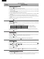
K NOISE FILTER TEST
CARRY OUT 3D CHECKS.
Disconnect the leads from the terminals of noise filter. Using an ohmmeter, check between the
terminals as described in the following table.
MEASURING POINT INDICATION OF OHMMETER
Between N and L Approx. 680 kΩ
Between terminal N and WHIT Short circuit
Between terminal L and BLK Short circuit
F3 : WEAK POINT
NOISE FILTER
NOISE SUPPRESSION COIL
DISCHARGE RESISTOR 680 kΩ 1/2W
DISCHARGE RESISTOR 10 MΩ 1/2W
LINE CROSS CAPACITOR 0.22µF/ AC250V
LINE CROSS CAPACITOR
10000 pF/ AC250V
LINE CROSS CAPACITOR
10000 pF/ AC250V
L
BLK
WHT
N
L HIGH VOLTAGE FUSE F4, F5 TEST
CARRY OUT 3D CHECKS.
If the high voltage fuse F4 (or F5) is blown, there could be a short in the high voltage rectifier or the magnetron
MG1 (or MG2). Check them and replace the defective parts and the high voltage fuse F4 (or F5).
CARRY OUT 4R CHECKS.
CAUTION: Only replace high voltage fuse with the correct value replacement.

16
R-25AM
M TOUCH CONTROL PANEL ASSEMBLY TEST
TEST PROCEDURES
PROCEDURE
LETTER COMPONENT TEST
The touch control panel consists of circuits including semiconductors such as LSI etc. Therefore,
unlike conventional microwave ovens, proper maintenance cannot be performed with only a
voltmeter and ohmmeter. In this service manual, the touch control panel assembly is divided into three
units, Control Unit, Switch Unit and Encoder Unit troubleshooting by unit replacement is described
according to the symptoms indicated.
1. Switch Unit Note :Check the lead wire harness connections among big and small switch units
and control unit before replacement.
The following symptoms indicate a defective switch unit. Replace the switch unit.
a) When touching the buttons, a certain button produces no signal at all.
b) When touching the buttons, sometimes a button produces no signal.
2. Encoder Note : Check the lead wire connection between encoder and control unit before
replacement.
The following symptoms indicate a defective encoder. Replace the encoder.
a) When rotating the encoder, the cooking time can not be entered.
3. Control Unit
The following symptoms may indicate a defective control unit. Replacing the control unit. Before
replacing the control unit, perform the switch unit test (Procedure N) to determine if control unit is
faulty.
3-1 Programming problems.
a) When touching the buttons, a certain group of buttons do not produce a signal.
3-2 Display problems.
a) For a certain digit, all or some segments do not light up.
b) For a certain digit, brightness is low.
c) Only one indicator does not light.
d) The corresponding segments of all digits do not light up; or they continue to light up.
e) Wrong figure appears.
f) A certain group of indicators do not light up.
g) The figure of all digits flicker.
3-3 Other possible problems caused by defective control unit.
a) Buzzer does not sound or continues to sound.
b) Cooking is not possible.
1. CARRY OUT
3D CHECKS.
2. Remove the switch unit from the control panel, referring to control panel removal.
3. To test the switches (SW1-SW5) on the switch unit, check between the terminals of the connector
CN-F as described in the following table by using ohmmeter when the switches are released and
depressed.
Switches Terminals Released Depressed
SW1 F1 - F4 O.C. S.C.
SW2 F1 - F5 O.C. S.C.
SW3 F2 - F4 O.C. S.C.
SW4 F2 - F5 O.C. S.C.
SW5 F3 - F4 O.C. S.C.
4. If incorrect readings are obtained, replace the defective switch.
5. CARRY OUT 4R CHECKS.
N SWITCH UNIT TEST
O RELAY TEST
CARRY OUT 3D CHECKS.
Remove the outer case and check voltage between Pin Nos. 3 and 5 of the connector (A) on the control
unit with an A.C. voltmeter. The meter should indicate 230 volts, if not check control unit circuity.
O.C. ----- Open Circuit
S.C. ----- Short Circuit

17
R-25AM
TEST PROCEDURES
PROCEDURE
LETTER COMPONENT TEST
RY1, RY3 and RY4 Relay Test
These relays are operated by D.C. voltage.
Check voltage at the relay coil with a D.C. voltmeter during the microwave cooking operation.
DC. voltage indicated .............................Defective relay.
DC. voltage not indicated .......................Check diode which is connected to the relay coil. If
diode is good, control unit is defective.
RELAY SYMBOL OPERATIONAL VOLTAGE CONNECTED COMPONENTS
RY1 APPROX. 25.9V D.C. Oven lamp, Blower motor and Antenna motors
RY3 APPROX. 25.0V D.C. High voltage transformer (MG1)
RY4 APPROX. 25.0V D.C. High voltage transformer (MG2)
CARRY OUT 4R CHECKS.
To protect the electronic circuits, this model is provided with a fine fuse added to the primary on the
PWB. If the fuse is open, follow the troubleshooting guide given below for repair.
Problem: POWER ON, indicator does not light up.
CARRY OUT 3D CHECKS.
STEPS OCCURRENCE CAUSE OR CORRECTION
1 The rated AC voltage is not present at Check supply voltage and oven power cord.
POWER terminal of CPU connector (CN-A).
2 The rated AC voltage is present at primary Touch control transformer or secondary circuit defective.
side of touch control transformer. Check and repair.
3 Fuse on the PWB is open. Replace the fuse with new one.
(CARRY OUT 3D CHECKS BEFORE REPAIR)
NOTE: *At the time of these repairs, make a visual inspection of the varistor for burning damage
and examine the transformer with tester for the presence of layer short-circuit (check
primary coil resistance). If any abnormal condition is detected, replace the defective parts.
CARRY OUT 4R CHECKS.
P PROCEDURES TO BE TAKEN WHEN THE FUSE ON THE PRINTED WIRING BOARD(PWB) IS
OPEN

18
R-25AM
2. Switch Unit
The switch unit is composed of a matrix circuit in which
when a switch it touched, one of signals P30 - P31
generated by the LSI, is passed through the switch
and returned to the LSI as one of signals P24 - P26.
3. Encoder
The encoder converts the signal generated by power
source circuit into the pulse signal, and the pulse
signal is sent to the LSI.
TOUCH CONTROL PANEL ASSEMBLY
OUTLINE OF TOUCH CONTROL PANEL
The touch control section consists of the following units as
shown in the touch control panel circuit.
(1) Control Unit
(2) Switch Unit
(3) Encoder Unit
The principal functions of these units and the signals
communicated among them are explained below.
1. Control Unit
Signal of key touch and oven function control are all
processed by one microcomputer.
1) Power Supply Circuit
This circuit changes output voltage at the secondary
side of the touch control transformer to voltages re-
quired at each part by full wave rectifying circuit,
constant voltage circuit, etc..
2) Reset Circuit
This is an Auto-clear Circuit, i.e., a reset circuit, which
enables IC1 to be activated from initial state.
3) Power Synchronizing Signal Generating Circuit
This is a circuit for generating power synchronizing
signal by virtue of the secondary side output of touch
control transformer.
This signal is used for a basic frequency to time
processing and so on.
4) Clock Circuit
This is a circuit for controlling clock frequency required
for operating I-1.
5) I-1 (Main Processor)
This is a one-chip microcomputer, responsible for
controlling the entire control unit.
6) I-2 (Memory Processor)
This is a memory IC, responsible for memory function.
7) Display Circuit
This is a circuit for driving display tubes by I-1 output.
8) Switch Input Circuit
This is a circuit for transmitting switch input information
to I-1.
9) Sound-body Driving Circuit
This is a circuit for driving sound body by I-1 output.
10) Relay Driving Circuit
This is a circuit for driving output relay by I-1 output.
11) Stop Switch Circuit
This is a circuit for driving I-1 to detect door opening/
closing.
12) Exhaust Air Temperature Detecting Circuit
This is a circuit for transmitting output change of
thermistor (Exhaust thermistor) to I-1.
13) Magnetron Temperature Circuit.
(Detect Noload or Fan Lock)
This is a circuit for transmitting output change of
thermistor (Magnetron thermistor) to I-1.
La pagina sta caricando ...
La pagina sta caricando ...
La pagina sta caricando ...
La pagina sta caricando ...
La pagina sta caricando ...
La pagina sta caricando ...
La pagina sta caricando ...
La pagina sta caricando ...
La pagina sta caricando ...
La pagina sta caricando ...
La pagina sta caricando ...
La pagina sta caricando ...
La pagina sta caricando ...
La pagina sta caricando ...
La pagina sta caricando ...
La pagina sta caricando ...
La pagina sta caricando ...
La pagina sta caricando ...
La pagina sta caricando ...
La pagina sta caricando ...
La pagina sta caricando ...
La pagina sta caricando ...
La pagina sta caricando ...
La pagina sta caricando ...
La pagina sta caricando ...
La pagina sta caricando ...
La pagina sta caricando ...
La pagina sta caricando ...
-
 1
1
-
 2
2
-
 3
3
-
 4
4
-
 5
5
-
 6
6
-
 7
7
-
 8
8
-
 9
9
-
 10
10
-
 11
11
-
 12
12
-
 13
13
-
 14
14
-
 15
15
-
 16
16
-
 17
17
-
 18
18
-
 19
19
-
 20
20
-
 21
21
-
 22
22
-
 23
23
-
 24
24
-
 25
25
-
 26
26
-
 27
27
-
 28
28
-
 29
29
-
 30
30
-
 31
31
-
 32
32
-
 33
33
-
 34
34
-
 35
35
-
 36
36
-
 37
37
-
 38
38
-
 39
39
-
 40
40
-
 41
41
-
 42
42
-
 43
43
-
 44
44
-
 45
45
-
 46
46
-
 47
47
-
 48
48


Sharp R-22AM Manuale utente
- Categoria
- Microonde
- Tipo
- Manuale utente
in altre lingue
- English: Sharp R-22AM User manual
Documenti correlati
Altri documenti
-
Stanley FME190 Manuale del proprietario
-
MrSteam Digital 30-Minute Timer Installation & Operation Manual
-
Biamp TC-225 Manuale utente
-
Blodgett Zephaire EF-111 Istruzioni per l'uso
-
Cembre MARKINGenius MG2 Manuale utente
-
Panasonic Microwave NE-1257C Manuale utente
-
Whirlpool UMV1160CB0 Guida d'installazione
-
Candy MSA 20 M Manuale utente
-
Kenmore 721.61282100 Manuale del proprietario
-
Realistic TM-1001 Manuale utente