Axial AXI03003T1 Manuale del proprietario
- Categoria
- Giocattoli telecomandati
- Tipo
- Manuale del proprietario

INSTRUCTION MANUAL
BEDIENUNGSANLEITUNG
MANUEL D’UTILISATION
MANUALE DI ISTRUZIONI
AXI03003 T1/T2

2
EN
Age Recommendation: Not for children under 14 years. This is not a toy.
WARNING: Read the ENTIRE instruction manual to become familiar with the features of the product before operating. Failure to operate
the product correctly can result in damage to the product, personal property and cause serious injury.
This is a sophisticated hobby product. It must be operated with caution and common sense and requires some basic mechanical ability. Failure to
operate this Product in a safe and responsible manner could result in injury or damage to the product or other property. This product is not intended for
use by children without direct adult supervision. Do not use with incompatible components or alter this product in any way outside of the instructions
provided by Horizon Hobby, LLC. This manual contains instructions for safety, operation and maintenance. It is essential to read and follow all the
instructions and warnings in the manual, prior to assembly, setup or use, in order to operate correctly and avoid damage or serious injury.
NOTICE
All instructions, warranties and other collateral documents are subject to change at the sole discretion of Horizon Hobby, LLC. For up-to-date
product literature, visit horizonhobby.com or towerhobbies.com and click on the support or resources tab for this product.
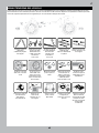
MEANING OF SPECIAL LANGUAGE
The following terms are used throughout the product literature to indicate various levels of potential harm when operating this product:
WARNING: Procedures, which if not properly followed, create the probability of property damage, collateral damage, and serious injury OR
create a high probability of superfi cial injury.
CAUTION: Procedures, which if not properly followed, create the probability of physical property damage AND a possibility of serious injury.
NOTICE: Procedures, which if not properly followed, create a possibility of physical property damage AND a little or no possibility of injury.
As the user of this product, you are solely responsible for operating in a manner that does not endanger yourself and others or result in damage
to the product or property of others.
This model is controlled by a radio signal subject to interference from many sources outside your control. This interference can cause momentary
loss of control, so it is advisable to always keep a safe distance in all directions around your model as this margin will help avoid collisions or injury.
• Never operate your model with low transmitter batteries.
• Always operate your model in open spaces away from full-size
vehicles, traffi c and people.
• Never operate the model in the street or in populated areas for any
reason.
• Carefully follow the directions and warnings for this and any optional
support equipment (chargers, rechargeable battery packs, etc.) you use.
• Keep all chemicals, small parts and anything electrical out of the
reach of children.
• Never lick or place any portion of the model in your mouth as it could
cause serious injury or even death.
• Exercise caution when using tools and sharp instruments.
• Take care during maintenance as some parts may have sharp edges.
• Immediately after using your model, do NOT touch equipment
such as the motor, electronic speed control and battery, because
they generate high temperatures. You may burn yourself seriously
touching them.
• Do not put fi ngers or any objects inside rotating and moving parts, as
this may cause damage or serious injury.
• Always turn on your transmitter before you turn on the receiver in the
car. Always turn off the receiver before turning your transmitter off.
• Keep the wheels of the model off the ground when checking the
operation of the radio equipment.
SAFETY PRECAUTIONS AND WARNINGS
WARNING AGAINST COUNTERFEIT PRODUCTS: Always purchase from a Horizon Hobby, LLC authorized dealer to ensure
authentic high-quality Spektrum product. Horizon Hobby, LLC disclaims all support and warranty with regards, but not limited to,
compatibility and performance of counterfeit products or products claiming compatibility with DSM® or Spektrum technology.

3
EN
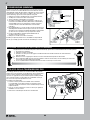
Your new Horizon Hobby vehicle has been designed and built with
a combination of waterproof and water-resistant components to
allow you to operate the product in many “wet conditions,” including
puddles, creeks, wet grass, snow and even rain.
While the entire vehicle is highly water-resistant, it is not completely
waterproof and your vehicle should NOT be treated like a submarine.
The various electronic components used in the vehicle, such as the
Electronic Speed Control (ESC), servo(s) and receiver are waterproof,
however, most of the mechanical components are water-resistant and
should not be submerged.
Metal parts, including the bearings, hinge pins, screws and nuts, as
well as the contacts in the electrical cables, will be susceptible to
corrosion if additional maintenance is not performed after running in
wet conditions. To maximize the long-term performance of your vehicle
and to keep the warranty intact, the procedures described in the “Wet
Conditions Maintenance” section below must be performed regularly
if you choose to run in wet conditions. If you are not willing to perform
the additional care and maintenance required, then you should not
operate the vehicle in those conditions.
CAUTION: Failure to exercise caution while using this
product and complying with the following precautions could
result in product malfunction and/or void the warranty.
GENERAL PRECAUTIONS
• Read through the wet conditions maintenance procedures and make
sure that you have all the tools you will need to properly maintain your
vehicle.
• Not all batteries can be used in wet conditions. Consult the battery
manufacturer before use. Caution should be taken when using Li-Po
batteries in wet conditions.
• Most transmitters are not water-resistant. Consult your transmitter’s
manual or the manufacturer before operation.
• Never operate your transmitter or vehicle where lightning may be present.
• Do not operate your vehicle where it could come in contact with salt
water (ocean water or water on salt-covered roads), contaminated
or polluted water. Salt water is very conductive and highly corrosive,
so use caution.
• Even minimal water contact can reduce the life of your motor if it
has not been certifi ed as water-resistant or waterproof. If the motor
becomes excessively wet, apply very light throttle until the water is
mostly removed from the motor. Running a wet motor at high speeds
may rapidly damage the motor.
• Driving in wet conditions can reduce the life of the motor. The
additional resistance of operating in water causes excess strain. Alter
the gear ratio by using a smaller pinion or larger spur gear. This will
increase torque (and motor life) when running in mud, deeper puddles,
or any wet conditions that will increase the load on the motor for an
extended period of time.
WET CONDITIONS MAINTENANCE
• Drain any water that has collected in the tires by spinning them at high
speed. With the body removed, place the vehicle upside down and pull
full throttle for a few short bursts until the water has been removed.
CAUTION: Always keep hands, fi ngers, tools and any loose
or hanging objects away from rotating parts when performing
the above drying technique.
• Remove the battery pack(s) and dry the contacts. If you have an air
compressor or a can of compressed air, blow out any water that may
be inside the recessed connector housing.
• Remove the tires/wheels from the vehicle and gently rinse the mud
and dirt off with a garden hose. Avoid rinsing the bearings and
transmission.
NOTICE: Never use a pressure washer to clean your vehicle.
• Use an air compressor or a can of compressed air to dry the vehicle
and help remove any water that may have gotten into small crevices or
corners.
• Spray the bearings, drive train, fasteners and other metal parts with
a water-displacing light oil. Do not spray the motor.
• Let the vehicle air dry before you store it. Water (and oil) may
continue to drip for a few hours.
• Increase the frequency of disassembly, inspection and lubrication of
the following:
- Front and rear axle hub assembly bearings.
- All transmission cases, gears and differentials.
- Motor—clean with an aerosol motor cleaner and re-oil the
bushings with lightweight motor oil.
WATER-RESISTANT VEHICLE WITH WATERPROOF ELECTRONICS
TABLE OF CONTENTS
Water-Resistant Vehicle with Waterproof Electronics ............................. 3
Box Contents.....................................................................................................4
Required Equipment ........................................................................................ 4
Recommended Tools ....................................................................................... 4
Getting Started Checklist ................................................................................ 5
Vehicle Parts ..................................................................................................... 5
Charge the Vehicle Battery ............................................................................6
Install the Transmitter Batteries ....................................................................6
Transmitter Functions ......................................................................................6
Adjusting the Vehicle Battery Tray................................................................7
Install the Vehicle Battery .............................................................................. 7
Binding ...............................................................................................................8
Range-Checking the Radio System ..............................................................8
Using the Dig Transmission ............................................................................8
Vehicle Maintenance ...................................................................................... 9
Spektrum Receiver/ESC Combo .................................................................. 10
Gear Ratios......................................................................................................10
Troubleshooting ..............................................................................................11
Limited Warranty ............................................................................................ 12
Warranty and Service Contact Information ..............................................12
FCC Information .............................................................................................. 13
IC Information .................................................................................................13
Compliance Information for the European Union ..................................... 13
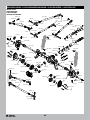
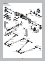
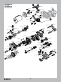
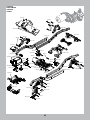
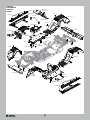
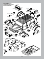
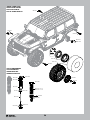
Exploded Views ..............................................................................................50
Parts List .......................................................................................................... 57
Optional Parts .................................................................................................60
Electronics ...................................................................................................... 60

4
EN
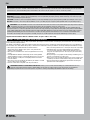
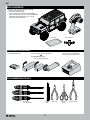
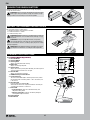
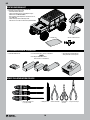
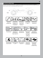
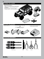
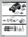
BOX CONTENTS
• Battery charger compatible with
the chosen vehicle battery type
• (4) AA Alkaline batteries
• Hex Drivers
(1.5, 2.0, 2.5mm)
• Hobby
Knife
• Side Cutter • Curved
Scissors
• Long-nose Plier
RECOMMENDED TOOLS
• Parts Bag • Cross Wrench
REQUIRED EQUIPMENT
• 2-3S Standard or “Shorty” LiPo Battery
OR
• 5-9 Cell NiMH/NiCd battery
(IC3
™
Connector Required)
• Spektrum
™
DX3
™
2.4GHz Transmitter (SPM2340)
• SCX10
™
III Jeep Wrangler RTR
- 35T Electric Motor (AX31312)
- Spektrum Receiver/ESC Combo (SPMXSE1040RX)
- Water Proof Metal Gear Surface Servo, 23T (SPMS614)
- SX107 Micro Analog Metal Gear Surface Servo
(For dig function) (SPMSSX107)

5
EN
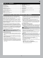
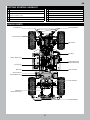
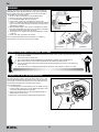
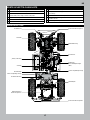
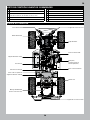
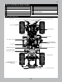
Steering Servo
Transmission
Driveshaft
Upper 4-link Bar
Differential
(inside axle housing)
Front Body Mount
Rear Body Mount
ESC Plug
Lower 4-link Bar
Shock Absorber
VEHICLE PARTS
GETTING STARTED CHECKLIST
Read the manual
Familiarize yourself with the vehicle and its components
Check all screws, especially the driveshaft setscrews, for
tightness from the factory
Charge the vehicle battery
Install 4 AA batteries in the transmitter
Power on the transmitter
Install the vehicle battery in the vehicle
Check for proper function of the throttle and steering
Range check the radio system
Drive the vehicle, challenge yourself and have FUN!
Perform any necessary vehicle maintenance
Steering Knuckle
“Shorty” Battery Tray
Standard Battery Tray
Receiver/Electronic
Speed Control (ESC)
Motor Cover

6
EN
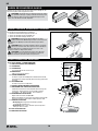
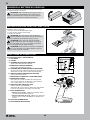
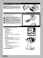
INSTALL THE TRANSMITTER BATTERIES
TRANSMITTER FUNCTIONS
This transmitter requires 4 AA batteries.
1. Remove the battery cover from the transmitter.
2. Install the batteries as shown.
3. Install the battery cover.
CAUTION: NEVER remove the transmitter batteries while the
model is powered on. Loss of model control, damage, or injury
may occur.
CAUTION: If using rechargeable batteries, charge only
rechargeable batteries. Charging non-rechargeable batteries
may cause the batteries to burst, resulting in injury to persons and/or
damage to property.
CAUTION: Risk of explosion if battery is replaced by an incorrect
type. Dispose of used batteries according to national regulations.
Channel 3 Button (Dig Function)
Throttle/Brake
Steering Wheel
Steering Rate
Adjusts the end point of the steering
Brake Rate
Adjusts the braking end point.
Steering Trim
Adjusts the steering center point. Normally, the steering trim is
adjusted until the vehicle tracks straight.
Throttle Trim
Adjusts the throttle neutral point
SMART Battery Level Indicator
Servo Reversing
To reverse the Throttle (TH) or Steering (ST) channel, switch
the position of the correlating switch—“N” is for normal, “R”
is for reverse.
Throttle Limit
Limits throttle output to 50/75/100%
Select 50% or 75% for less experienced drivers or when you
are driving the vehicle in a small area.
Power LED
• Solid red lights: Indicates radio connectivity and
adequate battery power
• Flashing red lights: Indicates the battery voltage is
critically low. Replace batteries
Power Button
Bind Button
C
D
H
J
K
L
I
G
F
E
M
N
A/B
A/B.
C.
D.
E.
F.
G.
H.
I.
J.
K.
L.
M.
N.
Follow the manufacturer’s directions for your charger to properly
charge the vehicle battery.
CAUTION: Only use chargers designed to charge the chosen
battery type. Using an incorrect charger or incorrect charger
settings could cause the battery to catch fi re or explode.
CHARGE THE VEHICLE BATTERY
Channel 3 Button (Dig Function)

7
EN
Power
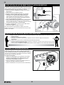
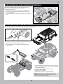
INSTALL THE VEHICLE BATTERY
2. Remove the four body clips from under the body.
3. Pull out slightly on the bottom sides of the body while lifting it
from the chassis.
4. Place the battery in the battery tray. The battery tray length may
be adjusted to fi t the battery as described in the previous section.
5. Secure the battery to the tray with the hook and loop strap.
6. Connect the battery to the ESC.
7. Power on the receiver/ESC.
8. Re-install the body and four body clips to the chassis.
NOTICE: Always power off the ESC and disconnect the battery
from the ESC before powering off the transmitter. Loss of vehicle
control may result.
1. Power on the transmitter.
ADJUSTING THE VEHICLE BATTERY TRAY
The battery trays may be adjusted to fi t a wide range of battery sizes.
The rear battery tray is shown in the illustration. The side battery tray
is adjustable in the same manner.
To adjust the battery tray:
1. Loosen the four fl athead screws shown in the illustration.
2. Slide the ends of the battery tray in or out to fi t the desired battery.
3. Tighten the four fl athead screws. Do not over-tighten the screws.
The following steps show the installation of a standard size battery in the rear battery tray of the vehicle. If you wish to use a “shorty” style
battery, it should be installed in the side battery tray location.

8
EN
BINDING
The radio system should be checked before operating the vehicle to ensure proper operation and adequate range.
1. Turn on the transmitter.
2. Connect the battery in the vehicle.
3. Have a friend hold the vehicle while keeping hands and loose clothing away from moving parts.
4. Walk away until you are at the maximum planned operating distance from the vehicle.
5. Turn the steering wheel side to side and operate the throttle, both forward and reverse, checking for any
erratic behavior.
6. If any erratic behavior is exhibited, DO NOT operate the vehicle. Call customer service for assistance.
RANGE-CHECKING THE RADIO SYSTEM
The vehicle includes a “Dig” transmission which allows the rear axle
to lock while still allowing the front wheels to spin. Use this feature in
close quarters to turn the vehicle tighter than is possible with normal
4 wheel drive or to preload the suspension when needed.
To use the Dig function:
1. Press and hold the channel 3 B button on the transmitter. The Dig
function engages, locking the rear axle. Hold the B button as long
as you want the dig function to be engaged.
2. Advance the throttle and turn the steering wheel left or right to
tightly pivot the vehicle around.
3. Release the channel 3 B button to disengage the Dig function.
USING THE DIG TRANSMISSION
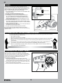
Binding is the process of programming the receiver to recognize the
GUID (Globally Unique Identifi er) code of a single specifi c transmitter.
The transmitter and receiver are bound at the factory. If you need to
rebind, follow the instructions below.
1. Connect a fully charged battery pack to the ESC/receiver.
2. Disconnect the “Dig” servo lead from the receiver.
3. Press and hold the bind button on the receiver.
4. Power ON the receiver. The red LED fl ashes, indicating the
receiver is in bind mode. Release the bind button after the red LED
begins to fl ash. The motor will make continuous descending tones
until binding is complete.
5. With the throttle trigger at neutral, press and hold the transmitter
bind button while powering on to put the transmitter in bind mode.
The throttle should be at neutral to set failsafe.
6. The bind process is complete when the green LED on the receiver
remains lit.
7. Connect the “Dig” servo lead to the receiver.
You must rebind when different failsafe positions are needed e.g.,
when throttle or steering reversing has been changed.
Bind Button
Bind ButtonPower Button
Power Switch

9
EN
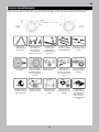
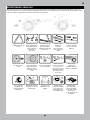
Replace any
noticeable bent or
broken parts
Check the wheel nuts
for tightness
If applicable, check
the slipper clutch for
proper operation
Check for wear on
the ball joints in
the steering and
suspension links
(replace if necessary)
Ensure the wheel
beads are still fi rmly
bonded around the
entire circumference
of the rim
Check the receiver
antenna for damage
Check driveshaft
set screws and
apply thread
locking compound if
necessary
Keep the chassis free
of dirt and debris
Check the steering
operation for any
binding
Inspect shock
absorbers for smooth
dampened operation
Check for loose
screws on the chassis,
especially the knuckle,
C-hub and axle lockout
screws
Inspect the spur
and pinion gears for
damage
Check for any loose
connections or frayed
wiring
Check the driveline
for smooth, bind free
operation
Replace the
transmitter batteries
when indicated by
the transmitter, as
described in the
Transmitter Functions
section
Just like a full size car or truck your RC vehicle must undergo periodic maintenance in order to ensure peak performance. Preventative maintenance
will also help avoid needless breakages which could result in costly repairs. Below are some suggestions to properly maintain your vehicle.
VEHICLE MAINTENANCE

10
EN
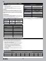
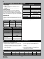
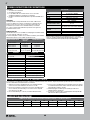
GEAR RATIOS
SPUR/PINION GEAR RATIO CHART - LCX TRANSMISSION
12 13 14 15 16 17 18
Low Speed (standard) 58.1 49.2 45.6 42.6 39.4 37.6 35.5
High Speed (optional) 39.8 36.5 31.3 29.2 27.3 25.7 24.3
SPEKTRUM RECEIVER/ESC COMBO
ESC AND TRANSMITTER CALIBRATION
OPERATION
1. Power on the transmitter.
2. Power on the receiver.
3. The green LED on the receiver will be illuminated when it is
connected to your transmitter.
4. Disconnect the battery from the ESC/Receiver after operation.
FAILSAFE
In the unlikely event that the radio link is lost during use, the 2-in-1 will
drive the throttle channel to the neutral (throttle off) position. If the 2-in-1 is
powered on prior to turning on the transmitter, it will enter failsafe mode,
leaving throttle off. When the transmitter is turned on, normal control will
resume.
LED INDICATORS
Upon powering ON the ESC, the red LED will blink and the motor will
emit a series of beeps to indicate its status.
The number of tones indicates (1) the ESC is in operation (2) the battery
mode detected and (3) the ESC is in a ready-to-use state.
FEATURE RED LED STATUS MOTOR SOUND
ESC Is In Operation
Rapid Blinking 4 Changing Tones
Ni-MH/Ni-CD Battery
2S Li-Po Battery
3S Li-Po Battery
1 Blink
2 Blinks
3 Blinks
1 Short Tone
2 Short Beeps
3 Short Beeps
ESC Ready,
No Transmitter Signal
2 Short Blinks,
Red Blink Repeating
2 Ascending Tones,
Descending Tones Repeating
OPERATION LED STATUS
Forward
Partial Throttle Green Solid, Red Blinks
Full Throttle Green and Red Solid
Reverse
Partial Throttle Green Solid, Red Blinks
Full Throttle Green and Red Solid
Brake
Partial Green Solid, Red Blinks
Full Green and Red Solid
Stop Green Solid
Battery Low Voltage or No Signal Red Blinks
Overheat Green Blinks
Over Current Protection Green and Red Triple Blinks
The included transmitter and ESC/receiver combo automatically
calibrate when powered on. Follow the procedure below to ensure
accurate calibration between the transmitter and ESC/receiver.
1. Connect a fully charged battery to the ESC/receiver. Ensure the
power switch is in the OFF position.
2. Power the transmitter ON. Ensure the throttle is not reversed, the
throttle trim is neutral and the throttle travel range is at 100%.
3. With the throttle at neutral, power ON the ESC/receiver.
4. Leave the throttle trigger and trims at neutral for at least 3
seconds.The ESC/Receiver automatically calibrates the throttle
range after 3 seconds.
5. The LED will blink and the motor will beep to indicate the battery
mode selection.
6. One long LED blink and one long beep indicates the ESC is ready to run.
SPECIFICATIONS
Type
Waterproof DSMR ESC/Receiver
2-in-1 with SMART Telemetry
Dimensions (L × W × H) 54mm × 33.5mm × 20.5mm
Antenna Length 31mm
Channels 4 (No Throttle Servo Output)
Weight 68g
Band 2404 MHz – 2476 MHz
Servo Output Voltage
6V up to 3A, Shared with Auxillary Light
Connectors
Telemetry Features
Battery Voltage, Current, ESC Temp,
Battery Data (with SMART Battery)
Battery Input Connector IC3
™
(EC3
™
Compatible)
Voltage Range 2–3S Li-Po*/5–9S NiMH
Max Current 40A Continuous/ 180A Burst
Motor Connectors 3.5mm Bullet
* Default setting for low voltage cutoff is Li-Po. Optional Dynamite
Program Card (DYNS3005) required to change the Battery Type Setting.

11
EN
TROUBLESHOOTING
PROBLEM POSSIBLE CAUSE SOLUTION
The system will not connect
Your transmitter and receiver are too
close together
Move transmitter 8 to 12 feet away from receiver
You are near metal objects Move to an area with less metal
The receiver is bound to a different
model memory
Make sure the correct model memory is active in your
transmitter
Your transmitter was placed into bind
mode and is no longer bound to your
receiver
Rebind your transmitter and receiver, and then re-calibrate
The receiver goes into failsafe a short
distance away from the transmitter
Check for damage on the receiver
antenna
Make sure your receiver antenna is protected and located
as high as practical
Replace the receiver or contact Horizon Product Support
The receiver stops responding during
operation
Low receiver battery voltage. If the
battery voltage is low, it may drop
below 3.5V momentarily, causing the
receiver to brown-out, then reconnect
Charge the receiver or vehicle battery. Spektrum receivers
require at least 3.5V to operate
Loose or damaged wires or connectors
between battery and receiver
Check the wires and connection between the battery and
receiver. Repair or replace wires and/or connectors
Vehicle does not move
Batteries are not installed properly in
the transmitter
Ensure the transmitter batteries are properly installed
Weak or no battery in the vehicle Install a freshly charged vehicle battery
Damaged motor Replace the motor
Frayed or broken wiring Replace any damaged wiring
ESC is shut down by heat protection circuit
Allow the ESC to cool down completely
Loss of vehicle control
Improper antenna placement
Ensure the transmitter antenna is not blocked and the
receiver antenna is located properly
Weak or no batteries in the transmitter
or vehicle
Install a freshly charged vehicle battery and new
transmitter batteries
Neutral or trim position is incorrect Adjust the steering trim
Receiver and/or battery not connected
properly
Check all receiver and battery connections
Steering and/or throttle function is
reversed
Servo travel is reversed at the transmitter Set the transmitter servo reversing switch to the correct position
Motor wires are not connected properly Check all motor wires for correct polarity and secure connection
ESC ON - No motor function, audible tone
or LED
Battery/connection issue Recharge/replace battery. Secure all connections
Damaged ESC/switch Repair/replace ESC switch/ESC
Damaged motor Repair/replace
Motor- Stops and LED blinks
Low voltage protection When the ESC LED blinks, recharge/replace battery
Overheat protection
When the LED blinks, let motor/ESC cool, change set up or
gearing to avoid overheating
Motor- Accelerates irregularly
Battery issue Repair damaged wiring/replace battery
Incorrect gearing Adjust/replace gearing
Worn or damaged motor Repair/replace motor
Motor- Does not turn continuously in
response to throttle
ESC/motor damaged Repair/replace wiring or motor/ESC
Motor- Slows but will not stop Incorrect transmitter/ESC calibration
Adjust throttle travel/other throttle settings on the
transmitter/ESC. Repeat the ESC Calibration Procedure
Steering servo- Operates; motor does not
run
Damaged motor
Test the motor apart from the vehicle system, repair/replace
motor as needed
Incorrect transmitter/ESC calibration
Adjust throttle travel/other throttle settings on the
transmitter/ESC. Repeat the ESC Calibration Procedure
Steering/motor- not functioning
Low battery voltage Recharge/replace
Wrong model memory selected on
transmitter
Select correct model settings on your transmitter, refer to
transmitter and/or receiver manual
Receiver not bound to transmitter
Bind transmitter to receiver, refer to transmitter and/or
receiver manual
Vehicle- Does not operate at full speed
Battery issue Recharge/replace
Incorrect transmitter/ESC calibration
Adjust throttle travel/other throttle settings on the
transmitter/ESC. Repeat the ESC Calibration Procedure

12
EN
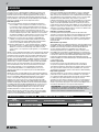
What this Warranty Covers
Horizon Hobby, LLC, (Horizon) warrants to the original purchaser that the
product purchased (the “Product”) will be free from defects in materials
and workmanship for a period of 2 years from the date of purchase.
What is Not Covered
This warranty is not transferable and does not cover (i) cosmetic damage,
(ii) damage due to acts of God, accident, misuse, abuse, negligence,
commercial use, or due to improper use, installation, operation or
maintenance, (iii) modifi cation of or to any part of the Product, (iv)
attempted service by anyone other than a Horizon Hobby authorized
service center, (v) Product not purchased from an authorized Horizon
dealer, or (vi) Product not compliant with applicable technical regulations
or (vii) use that violates any applicable laws, rules, or regulations.
OTHER THAN THE EXPRESS WARRANTY ABOVE, HORIZON MAKES NO
OTHER WARRANTY OR REPRESENTATION, AND HEREBY DISCLAIMS
ANY AND ALL IMPLIED WARRANTIES, INCLUDING, WITHOUT
LIMITATION, THE IMPLIED WARRANTIES OF NON-INFRINGEMENT,
MERCHANTABILITY AND FITNESS FOR A PARTICULAR PURPOSE. THE
PURCHASER ACKNOWLEDGES THAT THEY ALONE HAVE DETERMINED
THAT THE PRODUCT WILL SUITABLY MEET THE REQUIREMENTS OF
THE PURCHASER’S INTENDED USE.
Purchaser’s Remedy
Horizon’s sole obligation and purchaser’s sole and exclusive remedy
shall be that Horizon will, at its option, either (i) service, or (ii) replace,
any Product determined by Horizon to be defective. Horizon reserves
the right to inspect any and all Product(s) involved in a warranty
claim. Service or replacement decisions are at the sole discretion of
Horizon. Proof of purchase is required for all warranty claims. SERVICE
OR REPLACEMENT AS PROVIDED UNDER THIS WARRANTY IS THE
PURCHASER’S SOLE AND EXCLUSIVE REMEDY.
Limitation of Liability
HORIZON SHALL NOT BE LIABLE FOR SPECIAL, INDIRECT,
INCIDENTAL OR CONSEQUENTIAL DAMAGES, LOSS OF PROFITS OR
PRODUCTION OR COMMERCIAL LOSS IN ANY WAY, REGARDLESS OF
WHETHER SUCH CLAIM IS BASED IN CONTRACT, WARRANTY, TORT,
NEGLIGENCE, STRICT LIABILITY OR ANY OTHER THEORY OF LIABILITY,
EVEN IF HORIZON HAS BEEN ADVISED OF THE POSSIBILITY OF SUCH
DAMAGES. Further, in no event shall the liability of Horizon exceed the
individual price of the Product on which liability is asserted. As Horizon
has no control over use, setup, fi nal assembly, modifi cation or misuse,
no liability shall be assumed nor accepted for any resulting damage
or injury. By the act of use, setup or assembly, the user accepts all
resulting liability. If you as the purchaser or user are not prepared to
accept the liability associated with the use of the Product, purchaser
is advised to return the Product immediately in new and unused
condition to the place of purchase.
Law
These terms are governed by Illinois law (without regard to confl ict of law
principals). This warranty gives you specifi c legal rights, and you may also
have other rights which vary from state to state. Horizon reserves the right
to change or modify this warranty at any time without notice.
WARRANTY SERVICES
Questions, Assistance, and Services
Your local hobby store and/or place of purchase cannot provide
warranty support or service. Once assembly, setup or use of the Product
has been started, you must contact your local distributor or Horizon
directly. This will enable Horizon to better answer your questions and
service you in the event that you may need any assistance. For questions
or assistance, please visit our website at www.horizonhobby.com,
submit a Product Support Inquiry, or call the toll free telephone number
referenced in the Warranty and Service Contact Information section to
speak with a Product Support representative.
Inspection or Services
If this Product needs to be inspected or serviced and is compliant in
the country you live and use the Product in, please use the Horizon
Online Service Request submission process found on our website
or call Horizon to obtain a Return Merchandise Authorization (RMA)
number. Pack the Product securely using a shipping carton. Please
note that original boxes may be included, but are not designed to
withstand the rigors of shipping without additional protection. Ship
via a carrier that provides tracking and insurance for lost or damaged
parcels, as Horizon is not responsible for merchandise until it arrives
and is accepted at our facility. An Online Service Request is available
at http://www.horizonhobby.com/content/service-center_render-
service-center. If you do not have internet access, please contact
Horizon Product Support to obtain a RMA number along with
instructions for submitting your product for service. When calling
Horizon, you will be asked to provide your complete name, street
address, email address and phone number where you can be reached
during business hours. When sending product into Horizon, please
include your RMA number, a list of the included items, and a brief
summary of the problem. A copy of your original sales receipt must be
included for warranty consideration. Be sure your name, address, and
RMA number are clearly written on the outside of the shipping carton.
NOTICE: Do not ship Li-Po batteries to Horizon. If you have any
issue with a Li-Po battery, please contact the appropriate Horizon
Product Support offi ce.
Warranty Requirements
For Warranty consideration, you must include your original sales
receipt verifying the proof-of-purchase date. Provided warranty
conditions have been met, your Product will be serviced or replaced
free of charge. Service or replacement decisions are at the sole
discretion of Horizon.
Non-Warranty Service
Should your service not be covered by warranty, service will be
completed and payment will be required without notifi cation or
estimate of the expense unless the expense exceeds 50% of the retail
purchase cost. By submitting the item for service you are agreeing
to payment of the service without notifi cation. Service estimates
are available upon request. You must include this request with your
item submitted for service. Non-warranty service estimates will be
billed a minimum of 1/2 hour of labor. In addition you will be billed for
return freight. Horizon accepts money orders and cashier’s checks,
as well as Visa, MasterCard, American Express, and Discover cards.
By submitting any item to Horizon for service, you are agreeing to
Horizon’s Terms and Conditions found on our website http://www.
horizonhobby.com/content/service-center_render-service-center.
ATTENTION: Horizon service is limited to Product compliant in
the country of use and ownership. If received, a non-compliant
Product will not be serviced. Further, the sender will be responsible
for arranging return shipment of the un-serviced Product, through
a carrier of the sender’s choice and at the sender’s expense.
Horizon will hold non-compliant Product for a period of 60 days from
notifi cation, after which it will be discarded.
10/15
COUNTRY OF PURCHASE HORIZON HOBBY CONTACT INFORMATION ADDRESS
United States of America
Horizon Service Center
(Repairs and Repair Requests)
servicecenter.horizonhobby.com/RequestForm/
2904 Research Rd
Champaign, IL 61822
Horizon Product Support
(Product Technical Assistance)
productsupport@horizonhobby.com
877-504-0233
Sales
websales@horizonhobby.com
800-338-4639
European Union
Horizon Technischer Service service@horizonhobby.eu
Hanskampring 9
D 22885 Barsbüttel, Germany
Sales: Horizon Hobby GmbH +49 (0) 4121 2655 100
LIMITED WARRANTY
WARRANTY AND SERVICE CONTACT INFORMATION

13
EN
INSTRUCTIONS FOR DISPOSAL OF WEEE BY USERS IN THE EUROPEAN UNION
This product must not be disposed of with other waste. Instead, it is the user’s responsibility to dispose of their waste equipment by
handing it over to a designated collections point for the recycling of waste electrical and electronic equipment. The separate collection
and recycling of your waste equipment at the time of disposal will help to conserve natural resources and ensure that it is recycled in a
manner that protects human health and the environment. For more information about where you can drop off your waste equipment for
recycling, please contact your local city offi ce, your household waste disposal service or where you purchased the product.
EU COMPLIANCE STATEMENT:
Axial SCX10 III Jeep Wrangler (AXI03003)
Horizon Hobby, LLC hereby declares that this product is in compliance with the essential requirements and other relevant provisions of
the RED and EMC Directives.
A copy of the EU Declaration of Conformity is available online at: http://www.horizonhobby.com/content/support-render-compliance.
FCC INFORMATION
IC INFORMATION
COMPLIANCE INFORMATION FOR THE EUROPEAN UNION
CAN ICES-3 (B)/NMB-3(B)
Contains IC: 6157A-KATY1T
This device complies with Industry Canada licence-exempt RSS standard(s). Operation is subject to the following two conditions: (1) this device may not
cause interference, and (2) this device must accept any interference, including interference that may cause undesired operation of the device.
Contains FCC ID: BRWKATY1T
This device complies with part 15 of the FCC rules. Operation is subject to the following two conditions: (1) This device may not cause harmful
interference, and (2) this device must accept any interference received, including interference that may cause undesired operation.
CAUTION: Changes or modifi cations not expressly approved by the party responsible for compliance could void the user’s authority to
operate the equipment.
This product contains a radio transmitter with wireless technology which has been tested and found to be compliant with the applicable regulations
governing a radio transmitter in the 2.400GHz to 2.4835GHz frequency range.
SUPPLIER’S DECLARATION OF CONFORMITY
Axial SCX10 III Jeep Wrangler (AXI03003)
This device complies with part 15 of the FCC Rules. Operation is subject to the following two conditions: (1) This device may not cause harmful
interference, and (2) this device must accept any interference received, including interference that may cause undesired operation.
CAUTION: changes or modifi cations not expressly approved by the party responsible for compliance could void the user’s authority to
operate the equipment.
NOTE: This equipment has been tested and found to comply with the limits for a Class B digital device, pursuant to part 15 of the FCC Rules.
These limits are designed to provide reasonable protection against harmful interference in a residential installation. This equipment generates,
uses and can radiate radio frequency energy and, if not installed and used in accordance with the instructions, may cause harmful interference
to radio communications. However, there is no guarantee that interference will not occur in a particular installation. If this equipment does cause
harmful interference to radio or television reception, which can be determined by turning the equipment off and on, the user is encouraged to try
to correct the interference by one or more of the following measures:
• Reorient or relocate the receiving antenna.
• Increase the separation between the equipment and receiver.
• Connect the equipment into an outlet on a circuit different from that to which the receiver is connected.
• Consult the dealer or an experienced radio/TV technician for help.
Horizon Hobby, LLC
2904 Research Rd.,
Champaign, IL 61822
Email: compliance@horizonhobby.com
Web: HorizonHobby.com

14
DE
Nicht geeignet für Kinder unter 14 Jahren. Dies ist kein Spielzeug.
WARNUNG: Lesen Sie die GESAMTE Bedienungsanleitung, um sich vor dem Betrieb mit den Produktfunktionen vertraut zu machen.
Wird das Produkt nicht korrekt betrieben, kann dies zu Schäden am Produkt oder persönlichem Eigentum führen oder schwere
Verletzungen verursachen.
Dies ist ein hochentwickeltes Hobby-Produkt. Es muss mit Vorsicht und gesundem Menschenverstand betrieben werden und benötigt
gewisse mechanische Grundfähigkeiten. Wird dieses Produkt nicht auf eine sichere und verantwortungsvolle Weise betrieben, kann dies zu
Verletzungen oder Schäden am Produkt oder anderen Sachwerten führen. Versuchen Sie nicht ohne Genehmigung durch Horizon Hobby, LLC,
das Produkt zu zerlegen, es mit inkompatiblen Komponenten zu verwenden oder auf jegliche Weise zu erweitern. Diese Bedienungsanleitung
enthält Anweisungen für Sicherheit, Betrieb und Wartung. Es ist unbedingt notwendig, vor Zusammenbau, Einrichtung oder Verwendung alle
Anweisungen und Warnhinweise im Handbuch zu lesen und zu befolgen, damit es bestimmungsgemäß betrieben werden kann und Schäden
oder schwere Verletzungen vermieden werden.
HINWIES
Allen Anweisungen, Garantien und anderen zugehörigen Dokumenten sind Änderungen nach Ermessen von Horizon Hobby, LLC vorbehalten.
Aktuelle Produktliteratur fi nden Sie unter www.horizonhobby.com oder www.towerhobbies.com im Support-Abschnitt für das Produkt.
ERKLÄRUNG DER BEGRIFFE
Die folgenden Begriffe werden in der gesamten Produktliteratur verwendet, um auf unterschiedlich hohe Gefahrenrisiken beim Betrieb dieses
Produkts hinzuweisen:
WARNUNG: Wenn diese Verfahren nicht korrekt befolgt werden, ergeben sich wahrscheinlich Sachschäden, Kollateralschäden und
schwere Verletzungen ODER mit hoher Wahrscheinlichkeit oberfl ächliche Verletzungen.
ACHTUNG: Wenn diese Verfahren nicht korrekt befolgt werden, ergeben sich wahrscheinlich Sachschäden UND die Gefahr von schweren Verletzungen.
HINWEIS: Wenn diese Verfahren nicht korrekt befolgt werden, können sich möglicherweise Sachschäden UND geringe oder keine Gefahr
von Verletzungen ergeben.
Als Nutzer dieses Produktes, sind Sie allein verantwortlich, es in einer Art und Weise zu benutzen, die eine eigene Gefährdung und die anderer
oder Beschädigung an anderem Eigentum ausschließt.
Das Modell ist ferngesteuert und anfällig für bestimmte äußere Einfl üsse. Diese Einfl üsse können zum vorübergehenden Verlust der
Steuerfähigkeit führen, so dass es immer sinnvoll ist genügend Sicherheitsabstand in alle Richtungen um das Modell zu haben.
• Fahren Sie das Modell nie mit fast leeren oder schwachen
Senderbatterien.
• Betreiben Sie Ihr Modell stets auf offenen Geländen, weit ab von
Automobilen, Verkehr und Menschen.
• Fahren Sie Ihr Modell nicht auf der Straße oder belebten Plätzen.
• Beachten Sie vorsichtig alle Hinweise und Warnungen für das
Modell und allen dazu gehörigen Equipment.
• Halten Sie alle Chemikalien, Kleinteile und elektrische Bauteile aus
der Reichweite von Kindern.
• Lecken Sie niemals an Teilen von Ihrem Modell oder nehmen diese
in den Mund, da diese Sie ernsthaft verletzten oder töten können.
• Seien Sie immer aufmerksam wenn Sie Werkzeug oder scharfe
Instrumente verwenden.
• Seien Sie bei dem Bau vorsichtig, da einige Teile scharfe Kanten
haben könnten.
• Fassen Sie bitte unmittelbar nach dem Betrieb nicht den Motor,
Regler oder Akku an, da diese Teile sich sehr erwärmen können und
Sie sich bei dem berühren ernsthaft verbrennen können.
• Fassen Sie nicht in drehende oder sich bewegende Teile, da sich
sich ernsthaft dabei verletzen können.
• Schalten Sie immer zuerst den Sender ein, bevor Sie den Empfänger
im Fahrzeug einschalten.
• Stellen Sie das Fahrzeug mit den Rädern nicht auf den Boden, wenn
Sie die Funktionen überprüfen.
SICHERHEITSHINWEISE UND WARNUNGEN
WARNUNG VOR GEFÄLSCHTEN PRODUKTEN: Sollten Sie jemals eine Spektrum Komponente ersetzen wollen, kaufen Sie die
benötigten Ersatzteile immer bei Horizon Hobby oder einem von Horizon Hobby autorisierten Händler, um sicherzugehen, dass Sie beste
Spektrum Qualität erhalten. Horizon Hobby, LLC lehnt jedwede Haftung, Garantie und Serviceleistung in Bezug auf, aber nicht ausschließlich
für, Kompatibilitäts- und Leistungsansprüche von gefälschten Produkten oder Produkten, die angeben mit Spektrum kompatibel zu sein, ab.

15
DE
Wassergeschütztes Fahrzeug mit wasserdichter Elektronik .................15
Packungsinhalt ...............................................................................................16
Erforderliches Zubehör .................................................................................16
Empfohlene Werkzeuge ................................................................................ 16
Erste-Schritte-Checkliste ............................................................................. 17
Fahrzeugteile .................................................................................................. 17
Laden des Fahrzeug-Akkus ..........................................................................18
Einsetzen der Senderbattereien .................................................................. 18
Funktionen des Senders ............................................................................... 18
Anpassen des Akkufachs des Fahrzeugs .................................................. 19
Den Fahrzeug-Akku einsetzen ..................................................................... 19
Binden ..............................................................................................................20
Reichweitentest für das Funksystem durc .............................................. 20
Verwenden des Grabgetriebes ....................................................................20
Fahrzeugwartung ...........................................................................................21
Spektrum Empfänger/Geschwindigkeitsregler-Kombination ................. 22
Kalibrierung von Geschwindigkeitsregler und Sender ...........................22
Übertragungsverhältnis ................................................................................22
Problemlösung................................................................................................23
Eingeschränkte Garantie .............................................................................. 24
Garantie und Service Kontaktinformationen ............................................. 24
Konformitätshinweise für die Europäische Union .................................... 25
Explosionszeichnungen ................................................................................ 50
Teilelisten ........................................................................................................57
Optionale Teile ................................................................................................60
Electronik.........................................................................................................60
WASSERGESCHÜTZTES FAHRZEUG MIT WASSERDICHTER ELEKTRONIK
INHALTSVERZEICHNIS
Ihr neues Horizon Hobby Fahrzeug wurde mit einer Kombination von
wasserfesten und spritzwassergeschützen Komponenten ausgestattet,
die den Betrieb des Fahrzeuges unter nassen Bedingungen inklusive
Pfützen, Bächen, nassem Gra, Schnee oder sogar Regen ermöglichen.
Obwohl das Fahrzeug sehr wasserfest ausgelegt ist, ist es nicht
vollständig wasserdicht und sollte NICHT wie ein U-Boot behandelt
werden. Die verschiedenen elektronischen Komponenten wie der
elektronische Fahrtregler (ESC), die Servos und Empfänger sind
wasserdicht, die meisten mechanischen Komponenten sind nur
wasserbeständig und sollten daher nicht untergetaucht werden.
Metallteile, inklusive Lager, Bolzen Schrauben und Muttern wie auch die
Kontakte in den elektrischen Kabeln sind für Korrosion anfällig wenn nicht
zusätzliche Wartung nach jedem Betrieb in feuchter/nasser Umgebung
erfolgt. Um die Langzeitleistung und die Garantie ihres Fahrzeuges zu
erhalten, müssen Sie die Wartung wie in der Wartungsanleitung nach
Fahrten in nasser Umgebung beschrieben durchführen. Sollten Sie diese
zusätzliche Wartung nicht ausführen wollen, dürfen Sie ihr Fahrzeug unter
diesen Bedingungen nicht betreiben.
ACHTUNG: Mangelnde Auf merksamkeit bei dem Gebrauch
dieses Produktes in Verbindung mit den folgenden
Sicherheitshinweisen könnte zu Fehlfunktionen und zum Verlust der
Garantie führen.
ALLGEMEINE SICHERHEITSHINWEISE
• Bitte lesen Sie sich die Wartungsanleitung nach Fahrten in nasser
Umgebung sorgfältig durch und stellen sicher, dass Sie alle
Werkzeuge für eine Wartung des Fahrzeuges haben.
• Sie können nicht alle Akkutypen für Fahrten in nasser Umgebung
nutzen. Fragen Sie dazu vor dem Einsatz den Hersteller des Akkus.
Achtsamkeit und Vorsicht ist notwendig wenn Sie LiPo Akkus in
feuchten Umgebungen einsetzen.
• Die meisten Sender sind nicht wasserfest. Sehen Sie bitte dazu vor
Inbetriebnahme in der Bedienungsanleitung ihres Senders nach
oder kontaktieren Sie den Hersteller.
• Nehmen Sie niemals den Sender bei Blitzen oder Gewitter in Betrieb.
• Betreiben Sie ihr Fahrzeug nicht an Orten wo es in Kontakt mit
Salzwasser oder verschmutzten, belasteten Gewässern kommen
kann. Salzwasser ist sehr leitend und stark korrosionsfördernd, sein
Sie daher sehr achtsam.
• Schon geringer Wasserkontakt kann den Motor beschädigen wenn
er nicht für den Betrieb in Wasser ausgelegt ist. Sollte der Motor
nass geworden sein geben Sie etwas Gas bis die meiste Feuchtigkeit
vom Motor entfernt ist. Lassen Sie einen nassen Motor auf hoher
Geschwindigkeit laufen wird dieses den Motor sehr schnell beschädigen.
• Fahren in nasser Umgebung kann die Lebenszeit des Motors
reduzieren, da dieses den Motor stark beansprucht. Verändern
Sie die Untersetzung zu einem kleinerem Ritzel oder größeren
Zahnrad. Dieses erhöht das Drehmoment (und verlängert die
Motorlebensdauer) bei dem Betrieb in Matsch, tieferen Pfützen oder
anderen Bedingungen, die die Last des Motors für einen längeren
Zeitraum erhöhen.
WARTUNGSANLEITUNG NACH FAHRTEN IN NASSER
UMGEBUNG
• Entfernen Sie Wasser in den Reifen durch Gas geben. Nehmen Sie
die Karosserie ab, drehen das Fahrzeug auf den Kopf und geben ein
paar Mal kurz Vollgas bis das Wasser aus dem Reifen entfernt ist.
ACHTUNG: Halten Sie immer die Hände, Finger, Werkzeuge
und andere lose oder hängende Objekte weg von drehenden
Teilen wenn Sie diese Technik des Trocknens praktizieren.
• Entfernen Sie die Akkupacks und trocknen die Kontakte. Sollten Sie
einen Kompressor oder Druckluft zur Verfügung haben, blasen Sie
damit das Wasser aus dem Motorgehäuse.
• Nehmen Sie die Reifen und Felgen vom Fahrzeug ab und spülen Sie
vorsichtig mit einem Gartenschlauch ab. Vermeiden Sie die Lager
oder den Antrieb direkt zu spülen.
HINWEIS: Verwenden Sie keinen Hochdruckreiniger um das
Fahrzeug zu reinigen.
• Reinigen Sie das Fahrzeug mit Druckluft aus einem Kompressor oder
einer Druckluftfl asche und entfernen so das Wasser aus den Spalten
und Ecken.
• Sprühen Sie alle Lager, Befestigungen und andere Metallteile mit
einem wasserverdrängendem Leichtöl oder Schmiermittel ein.
Sprühen Sie nicht den Motor ein.
• Lassen Sie das Fahrzeug vor dem Einlagern vollständig trocknen. Das
Abtropfen von Wasser (und Öl) kann durchaus ein paar Stunden dauern.
• Erhöhen Sie die Wartungsintervalle (Demontage, Inspektion und
schmieren) von folgenden Komponenten:
- Vorder- und Hinterachse, Aufnahme und Lager.
- Alle Antriebswellen Lager, Gehäuse, Getriebe und Differentiale.
- Motor: reinigen Sie den Motor mit einen Aerosol Reiniger
und ölen Sie dann die Lager mit leichtem Motoröl.

16
DE
PACKUNGSINHALT
• Akkuladegerät kompatibel mit
dem gewählten Fahrzeugakku
• (4) AA-Alkali-Batterien
EMPFOHLENE WERKZEUGE
ERFORDERLICHES ZUBEHÖR
• Sechskantschlüssel
(1,5, 2,0, 2,5mm)
• Hobbymesser • Seitenschneider • Gebogene
Schere
• Langnasenzange
• Teilebeutel • Kreuzschlitzschlüssel
• 2–3S Standard- oder „Shorty“-LiPo-Akku
ODER
• 5–9-zelliger NiMH/NiCd-Akku
(IC3-Anschluss erforderlich)
• Spektrum DX3 2,4-GHz-Sender (SPM2340)
• SCX10 III JeepWrangler RTR
- 35T Elektromotor (AX31312)
- Spektrum Empfänger/Geschwindigkeitsregler-
Kombination (SPMXSE1040RX)
- Wasserdichter Metallgetriebe-Oberfl ächenservo,
23T (SPMS614)
- SX107 Analoger Micro-Metallgetriebe-
Oberfl ächenservo (Für Grabfunktion) (SPMSSX107)

17
DE
Servolenkung
Getriebe
Antriebswelle
Obere viergliedrige Stange
Differentialsperre
(Innenachsgehäuse
Karosseriehalterung vorne
ESC-Stecker
Untere viergliedrige Stange
Stoßdämpfer
FAHRZEUGTEILE
ERSTE-SCHRITTE-CHECKLISTE
Lesen Sie das Handbuch
Machen Sie sich mit dem Fahrzeug und seinen Komponenten vertraut
Alle Schrauben, insbesondere die Feststellschrauben der
Antriebswelle, werksseitig auf festen Sitz prüfen
Laden des Fahrzeug-Akkus
Die 4 AA-Batterien in den Sender einsetzen
Den Sender einschalten
Die Akkus in das Fahrzeug einsetzen
Überprüfen der ordnungsgemäßen Funktion der Gaszufuhr und
der Lenkung
Reichweitentest für das Funksystem durchführen
Fahren Sie das Fahrzeug, fordern Sie sich selbst heraus und
genießen Sie es!
Notwendige Wartungsmaßnahmen am Fahrzeug vornehmen
Lenkrolle
„Shorty“-Akkufach
Standard-Akkufach
Empfänger/
Geschwindigkeitsregler
(ESC)
Motorabdeckung
Karosseriehalterung hinten

18
DE
EINSETZEN DER SENDERBATTEREIEN
FUNKTIONEN DES SENDERS
Für den Betrieb sind 4 AA Batterien erforderlich.
1. Nehmen Sie die Batterieklappe vom Sender ab.
2. Setzen Sie die Batterien wie abgebildet ein.
3. Setzen Sie die Batterieklappe wieder auf.
ACHTUNG: Entfernen Sie niemals Batterien aus dem
Sender, während das Modell eingeschaltet ist. Ein Verlust der
Kontrolle über das Modell, Schäden oder Verletzungen können
auftreten.
ACHTUNG: Wenn Sie wiederaufl adbare Akkus verwenden
dürfen Sie nur diese laden. Das Laden von nicht aufl adbaren
Batterien könnte diese zur Explosion bringen, was Sach- und
Personenschäden zur Folge haben könnte.
ACHTUNG: Es besteht Explosionsrisiko wenn die Akkus
durch einen falschen Typ ersetzt werden. Entsorgen Sie
verbrauchte Batterien den Vorschriften entsprechend.
C
D
H
J
K
L
I
G
F
E
M
N
A/B
A/B.
C.
D.
E.
F.
G.
H.
I.
J.
K.
L.
M.
N.
Befolgen Sie die Anweisungen des Herstellers Ihres Ladegeräts, um
den Fahrzeug-Akku ordnungsgemäß zu laden.
ACHTUNG: Verwenden Sie nur Ladegeräte, die für das Laden
des gewählten Akkutyps ausgelegt sind. Die Verwendung eines
falschen Ladegeräts oder eine falsche Ladeeinstellung kann dazu
führen, dass der Akku brennt oder explodiert.
LADEN DES FAHRZEUG-AKKUS
TASTE KANAL3 (GRABFUNKTION)
THROTTLE/BRAKE (GAS/BREMSE)
STEUERRAD
STEUERRATE
Passt den Endpunkt der Steuerung an
BRAKE RATE
Adjusts the braking end point.
STEUERTRIMMUNG
Zur Anpassung des Steuermittelpunkts. Normalerweise wird die
Steuertrimmung solange eingestellt, bis das Fahrzeug gerade in der
Spur läuft.
GASTRIMMUNG
Zur Anpassung des Gasnullpunktes
LADEZUSTANDSANZEIGE SMART-AKKU
UMKEHREN DER SERVOLAUFRICHTUNG
Um den Kanal für die Gaszufuhr (TH) oder die Steuerung (ST)
umzukehren, die Position des entsprechenden Schalters
umschalten – „N“ steht für normal, „R“ für Umkehren.
BEGRENZUNG GASZUFUHR
Begrenzt die Gaszufuhr auf 50/75/100%
Wählen Sie 50oder 75% für Fahrer mit weniger Erfahrung oder
wenn das Fahrzeug in einem kleinen Gebiet gefahren wird.
ANZEIGE-LEUCHTEN
• Durchgängig rot: Zeigt die Funkverbindung und die
ausreichende Akkuladung an
• Rot blinkend: Zeigt an, dass die Akku-Spannung kritisch
niedrig ist. Akkus ersetzen
EIN-/AUSSCHALTER
BINDUNGSSCHALTER

19
DE
DEN FAHRZEUG-AKKU EINSETZEN
Schalter
An / Aus
2. Die vier Gehäuseklemmen unter dem Gehäuse entfernen.
3. Leicht von den unteren Seiten des Gehäuses herausziehen,
während es von der Karosserie gehoben wird.
4. Den Akku im Akkufach einsetzen. Die Länge des Akkufachs
kann entsprechend der Beschreibung im vorherigen Kapitel
für das Einpassen des Akkus angepasst werden.
5. Den Akku mit den Klettbändern am Akkufach sichern.
6. Den Akku an den Geschwindigkeitsregler anschließen.
7. Den Empfänger/Geschwindigkeitsregler einschalten.
8. Das Gehäuse und die vier Gehäuseklemmen wieder an der
Karosserie montieren.
HINWEIS: Vom dem Ausschalten des Senders immer
den Geschwindigkeitsregler ausschalten und den Akku
vom Geschwindigkeitsregler trennen. Ein Schaden an der
Fahrzeugsteuerung kann die Folge sein.
1. Den Sender einschalten.
ANPASSEN DES AKKUFACHS DES FAHRZEUGS
Die Akkufächer können zur Aufnahme einer großen Bandbreite an
Akkugrößen angepasst werden. Das hintere Akkufach wird in der
Abbildung dargestellt. Das seitliche Akkufach kann in gleicher Weise
angepasst werden.
Zum Anpassen des Akkufachs:
1. Die vier in der Abbildung dargestellten Flachkopfschrauben lösen.
2. Die Enden des Akkufachs hinein oder herausschieben, damit der
gewünschte Akku passt.
3. Die vier Flachkopfschrauben festziehen. Die Schrauben nicht zu
fest anziehen.
Die nachfolgenden Schritte zeigen die Montage eines Akkus in Standardgröße im hinteren Akkufach des Fahrzeugs. Soll ein „Shorty“-artiger
Akku verwendet werden, diesen im seitlichen Akkufach montieren.

20
DE
BINDEN
Das Funksystem sollte vor dem Betrieb des Fahrzeugs überprüft werden, um einen ordnungsgemäßen Betrieb und eine
ausreichende Reichweite zu gewährleisten.
1. Den Sender einschalten.
2. Den Akku an das Fahrzeug anschließen.
3. Bitten Sie jemanden das Fahrzeug zu halten, damit Sie Hände und lose Kleidung von beweglichen Teilen fernhalten können.
4. Bewegen Sie sich so weit vom Fahrzeug weg, bis Sie den maximal geplanten Betriebsabstand zum Fahrzeug
erreicht haben.
5. Drehen Sie das Steuerrad von einer Seite zur anderen und betätigen Sie die Gaszufuhr, sowohl vorwärts als
auch rückwärts, und achten Sie darauf, ob Sie irgendein unregelmäßiges Verhalten bemerken.
6. Wenn ein unregelmäßiges Verhalten auftritt, dürfen Sie das Fahrzeug NICHT zum Einsatz bringen. Wenden Sie
sich in diesem Fall an den Kundendienst.
REICHWEITENTEST FÜR DAS FUNKSYSTEM DURC
Der Capra mit Achse umfasst ein Grabgetriebe, mit dem die
Hinterachse gesperrt werden kann, während sich die Vorderräder
noch drehen. Die Nutzung dieser Funktion erfolgt in engen Bereichen,
um das Fahrzeug enger als mit einem normalen Vierradantrieb zu
wenden oder die Aufhängung bei Bedarf vorzuspannen.
Verwendung der Grabfunktion:
1. Die Taste Kanal 3 B auf dem Sender gedrückt halten. Die
Grabfunktion wird aktiviert und sperrt die Hinterachse. Die Taste B
solange gedrückt halten, wie die Grabfunktion aktiviert sein soll.
2. Die Gaszufuhr erhöhen und das Steuerrad nach links oder rechts
drehen, um das Fahrzeug eng zu wenden.
3. Die Taste Kanal 3 B zum Deaktivieren der Grabfunktion loslassen.
VERWENDEN DES GRABGETRIEBES
Bindungsschalter
BindungsschalterEin-/Ausschalter
Stromschalter
Das Binden ist der Vorgang, durch den der Empfänger darauf
programmiert wird, den GUID-Code (Globally Unique Identifi er) eines
einzelnen Senders zu erkennen. Der Sender und der Empfänger sind
werksseitig gebunden. Muss eine erneute Bindung durchgeführt
werden, so ist die nachfolgende Anleitung zu befolgen.
1. Ein voll aufgeladenes Akkupack mit dem Geschwindigkeitsregler/
Empfänger verbinden.
2. Die „Dig“-Servoleitung vom Empfänger trennen.
3. Den Bindungsschalter am Sender gedrückt halten.
4. Den Empfänger einschalten. Die rote LED blinkt und zeigt an,
dass sich der Empfänger im Bindungsmodus befi ndet. Den
Bindungsschalter loslassen, nachdem die rote LED zu blinken
beginnt. Der Motor gibt durchgängig absteigende Töne aus, bis
das Binden abgeschlossen ist.
5. Der Gasauslöser befi ndet sich in Neutral, den Bindungsschalter
des Senders während des Einschaltens gedrückt halten, um den
Sender in den Bindungsmodus zu versetzen. Gas sollte auf Neutral
stehen, um Failsafe einzurichten.
6. Der Bindungsvorgang ist abgeschlossen, wenn die grüne LED auf
dem Empfänger durchgängig leuchtet.
7. Die „Dig“-Servoleitung mit dem Empfänger verbinden.
Ein erneutes Binden muss durchgeführt werden, wenn andere
Failsafe-Positionen erforderlich sind, z.B. wenn Gas oder Steuerung
umgekehrt wurden.
La pagina si sta caricando...
La pagina si sta caricando...
La pagina si sta caricando...
La pagina si sta caricando...
La pagina si sta caricando...
La pagina si sta caricando...
La pagina si sta caricando...
La pagina si sta caricando...
La pagina si sta caricando...
La pagina si sta caricando...
La pagina si sta caricando...
La pagina si sta caricando...
La pagina si sta caricando...
La pagina si sta caricando...
La pagina si sta caricando...
La pagina si sta caricando...
La pagina si sta caricando...
La pagina si sta caricando...
La pagina si sta caricando...
La pagina si sta caricando...
La pagina si sta caricando...
La pagina si sta caricando...
La pagina si sta caricando...
La pagina si sta caricando...
La pagina si sta caricando...
La pagina si sta caricando...
La pagina si sta caricando...
La pagina si sta caricando...
La pagina si sta caricando...
La pagina si sta caricando...
La pagina si sta caricando...
La pagina si sta caricando...
La pagina si sta caricando...
La pagina si sta caricando...
La pagina si sta caricando...
La pagina si sta caricando...
La pagina si sta caricando...
La pagina si sta caricando...
La pagina si sta caricando...
La pagina si sta caricando...
La pagina si sta caricando...
La pagina si sta caricando...
La pagina si sta caricando...
La pagina si sta caricando...
-
 1
1
-
 2
2
-
 3
3
-
 4
4
-
 5
5
-
 6
6
-
 7
7
-
 8
8
-
 9
9
-
 10
10
-
 11
11
-
 12
12
-
 13
13
-
 14
14
-
 15
15
-
 16
16
-
 17
17
-
 18
18
-
 19
19
-
 20
20
-
 21
21
-
 22
22
-
 23
23
-
 24
24
-
 25
25
-
 26
26
-
 27
27
-
 28
28
-
 29
29
-
 30
30
-
 31
31
-
 32
32
-
 33
33
-
 34
34
-
 35
35
-
 36
36
-
 37
37
-
 38
38
-
 39
39
-
 40
40
-
 41
41
-
 42
42
-
 43
43
-
 44
44
-
 45
45
-
 46
46
-
 47
47
-
 48
48
-
 49
49
-
 50
50
-
 51
51
-
 52
52
-
 53
53
-
 54
54
-
 55
55
-
 56
56
-
 57
57
-
 58
58
-
 59
59
-
 60
60
-
 61
61
-
 62
62
-
 63
63
-
 64
64


Axial AXI03003T1 Manuale del proprietario
- Categoria
- Giocattoli telecomandati
- Tipo
- Manuale del proprietario
in altre lingue
- English: Axial AXI03003T1 Owner's manual
- français: Axial AXI03003T1 Le manuel du propriétaire
- Deutsch: Axial AXI03003T1 Bedienungsanleitung
Documenti correlati
-
Axial AXI03001T1 Manuale del proprietario
-
-
-
-
-
-
Axial AXI00002T1 Manuale del proprietario
-
-
-
Axial AXI03016T1 Manuale del proprietario
Altri documenti
-
Horizon AX103002 Manuale utente
-
ECX ECX03028 Manuale del proprietario
-
ECX Revenge E Manuale utente
-
-
ProBoat PRB08037T1 Manuale del proprietario
-
Pro Boat Miss GEICO Zelos Manuale del proprietario
-
ECX ECX03017 Manuale del proprietario
-
-
Spektrum SPMXSE1040RX Manuale del proprietario
-
Horizon Hobby S6240RX Hi-Torq Hi-Spd Servo Manuale utente