
TK-7180/ TK-8180
TK-7189/ TK-8189
VHF FM TRANSCEIVER/ UHF FM TRANSCEIVER
INSTRUCTION MANUAL
ÉMETTEUR-RÉCEPTEUR FM VHF/ ÉMETTEUR-RÉCEPTEUR FM UHF
MODE D’EMPLOI
TRANSCEPTOR FM VHF/ TRANSCEPTOR FM UHF
MANUAL DE INSTRUCCIONES
RICETRASMETTITORE FM VHF/ RICETRASMETTITORE FM UHF
MANUALE DI ISTRUZIONI
VHF-FM-TRANSCEIVER/ UHF-FM-TRANSCEIVER
BEDIENUNGSANLEITUNG
VHF FM ZENDONTVANGER/ UHF FM ZENDONTVANGER
GEBRUIKSAANWIJZING
B62-1767-50 (E)
1 2 3
4 5 6
7 8 9
0
#

Importeur
Amsterdamseweg 37, 1422 AC Uithoorn, Nederland
Importer
12 Priestley Way, London NW2 7BA, United Kingdom
Importeur
Konrad-Adenauer-Allee 1-11, 61118 Bad Vilbel, Deutschland
Importador
Carretera de Rubi, 88 Planta 1A, 08174 Sant Cugat del Vallès Barcelona, España
Importateur
7 Allee des Barbanniers 92230 Gennevilliers, France
Importatore
Via G. Sirtori 7/9, 20129 Milano, Italia
Importeur
Leuvensesteenweg 248J, 1800 Vilvoorde, België
Authorised Representative in Europe
Amsterdamseweg 37, 1422 AC Uithoorn, Nederland
Manufacturer
3-12, Moriyacho, Kanagawa-ku, Yokohama-shi, Kanagawa, 221-0022, JAPAN

VHF FM TRANSCEIVER/
UHF FM TRANSCEIVER
TK-7180/ TK-8180
TK-7189/ TK-8189
INSTRUCTION MANUAL
ENGLISH
NOTIFICATION
This equipment complies with the essential requirements of
Directive 2014/53/EU.
This equipment requires a licence and is intended for use in
the countries as below.
AT BE DK FI FR DE GR IS IE
IT LI LU NL NO PT ES SE CH
GB CY CZ EE HU LV LT MT PL
SK SI BG RO HR TR
ISO3166

Information on Disposal of Old Electrical and Electronic Equipment and Batteries
(applicable for countries that have adopted separate waste collection systems)
Products and batteries with the symbol (crossed-out wheeled bin) cannot be
disposed as household waste.
Old electrical and electronic equipment and batteries should be recycled at a
facility capable of handling these items and their waste byproducts.
Contact your local authority for details in locating a recycle facility nearest to you.
Proper recycling and waste disposal will help conserve resources whilst
preventing detrimental effects on our health and the environment.
Firmware Copyrights
The title to and ownership of copyrights for fi rmware
embedded in KENWOOD product memories are reserved for JVC KENWOOD
Corporation.

i
THANK YOU
We are grateful you chose .(1:22' for your personal mobile applications. We
believe this easy-to-use transceiver will provide dependable communications to
keep personnel operating at peak efficiency.
KENWOOD transceivers incorporate the latest in advanced technology. As a
result, we feel strongly that you will be pleased with the quality and features of this
product.
MODELS COVERED BY THIS MANUAL
The models listed below are covered by this manual:
• TK-7180: VHF FM Transceiver
• TK-7189: VHF FM Transceiver (with front panel keypad)
• TK-8180: UHF FM Transceiver
• TK-8189: UHF FM Transceiver (with front panel keypad)
NOTICES TO THE USER
◆ Government law prohibits the operation of unlicensed transmitters within the territories under
government control.
◆ Illegal operation is punishable by fine and/or imprisonment.
◆ Refer service to qualified technicians only.
SAFETY: It is important that the operator is aware of, and understands, hazards
common to the operation of any transceiver.
◆ EXPLOSIVE ATMOSPHERES (GASES, DUST, FUMES, etc.)
Turn OFF your transceiver while taking on fuel or while parked in gasoline service stations. Do
not carry spare fuel containers in the trunk of your vehicle if your transceiver is mounted in the
trunk area.
◆ INJURY FROM RADIO FREQUENCY TRANSMISSIONS
Do not operate your transceiver when somebody is either standing near to or touching the
antenna, to avoid the possibility of radio frequency burns or related physical injury.
◆ DYNAMITE BLASTING CAPS
Operating the transceiver within 500 feet (150 m) of dynamite blasting caps may cause them
to explode. Turn OFF your transceiver when in an area where blasting is in progress, or where
“TURN OFF TWO-WAY RADIO” signs have been posted. If you are transporting blasting caps
in your vehicle, make sure they are carried in a closed metal box with a padded interior. Do not
transmit while the caps are being placed into or removed from the container.

ii
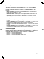
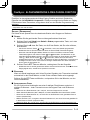
PRECAUTIONS
Observe the following precautions to prevent fire, personal injury, and transceiver
damage.
• Do not attempt to configure the transceiver while driving; it is too dangerous.
• Do not disassemble or modify the transceiver for any reason.
• Do not expose the transceiver to long periods of direct sunlight, nor place it near heating
appliances.
• Do not place the transceiver in excessively dusty, humid, or wet areas, nor on unstable
surfaces.
• If an abnormal odor or smoke is detected coming from the transceiver, switch the
transceiver power off immediately, and contact your Kenwood dealer.
• Use of the transceiver while you are driving may be against traffic laws. Please check
and observe the vehicle regulations in your area.
• Do not use options not specified by Kenwood.
◆ The transceiver operates in 12 V negative ground systems only! Check the battery polarity and
voltage of the vehicle before installing the transceiver.
◆ Use only the supplied DC power cable or a Kenwood optional DC power cable.
◆ Do not cut and/or remove the fuse holder on the DC power cable.
For passenger safety, install the transceiver securely using the supplied mounting bracket and
screw set so the transceiver will not break loose in the event of a collision.

iii
CONTENTS
UNPACKING AND CHECKING EQUIPMENT ....................................1
SUPPLIED ACCESSORIES .......................................................................1
PREPARATION ...................................................................................2
TOOLS REQUIRED ................................................................................2
POWER CABLE CONNECTION .................................................................2
INSTALLING THE TRANSCEIVER ...............................................................3
GETTING ACQUAINTED .....................................................................4
FRONT PANEL .....................................................................................4
REAR PANEL ......................................................................................4
DISPLAY ............................................................................................. 6
PROGRAMMABLE FUNCTIONS ........................................................7
BASIC OPERATIONS ..........................................................................8
OVERVIEW ..........................................................................................8
SWITCHING POWER ON/ OFF ..............................................................8
ADJUSTING THE VOLUME .......................................................................8
SELECTING A ZONE AND CHANNEL .........................................................9
TRANSMITTING ..................................................................................... 9
RECEIVING ..........................................................................................9
CONVENTIONAL SCAN ....................................................................10
ADD TO SCAN/ DELETE FROM SCAN .....................................................10
SCAN REVERT ...................................................................................11
PRIORITY SCAN .................................................................................11
QUIET TALK (QT)/ DIGITAL QUIET TALK (DQT) ............................12
OPERATOR SELECTABLE TONE (OST) .................................................12
5-TONE SIGNALING .........................................................................13
MAKING A SELCALL (SELECTIVE CALL) .................................................13
TRANSMITTING A STATUS MESSAGE ...................................................... 13
RECEIVING SELCALLS AND STATUS MESSAGES ......................................14
REVIEWING MESSAGES IN THE QUEUE MEMORY......................................14

iv
FleetSync: ALPHANUMERIC 2-WAY PAGING FUNCTION ............15
S
ELCALL (SELECTIVE CALLING) ...........................................................15
S
TATUS MESSAGE .............................................................................16
SHORT MESSAGES ............................................................................. 17
LONG MESSAGES ..............................................................................17
GPS REPORT ...................................................................................17
DTMF (DUAL TONE MULTIE FREQUENCY) CALLS ......................18
MANUAL DIALING...............................................................................18
AUTODIAL ......................................................................................... 18
REDIAL ............................................................................................18
CONNECT/ DISCONNECT IDS................................................................19
DTMF SIGNALING ............................................................................. 19
STUN ...............................................................................................19
EMERGENCY CALLS .......................................................................20
ADVANCED OPERATIONS ..............................................................21
TALK AROUND ..................................................................................21
MONITOR/ SQUELCH OFF .................................................................... 21
SCRAMBLER ...................................................................................... 22
CLOCK ............................................................................................. 22
LCD BRIGHTNESS ............................................................................. 23
HORN ALERT ....................................................................................23
PUBLIC ADDRESS (PA) ......................................................................23
BACKGROUND OPERATIONS ........................................................24
TIME-OUT TIMER (TOT) .....................................................................24
BUSY CHANNEL LOCKOUT (BCL) ........................................................24
SIGNAL STRENGTH INDICATOR .............................................................24
BEGINNING/ END OF TRANSMIT SIGNAL .................................................24
VGS-1 OPTIONAL VOICE GUIDE & STORAGE UNIT .....................25
VOICE RECORDER .............................................................................. 25
VOICE GUIDE ....................................................................................26

1
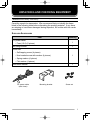
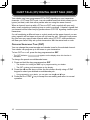
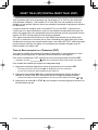
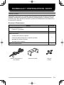
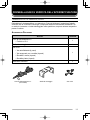
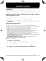
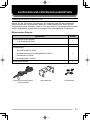
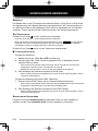
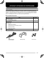
UNPACKING AND CHECKING EQUIPMENT
Note: The following unpacking instructions are for use by your Kenwood dealer, an authorized
Kenwood service facility, or the factory.
Carefully unpack the transceiver. We recommend that you identify the items
listed in the following table before discarding the packing material. If any items
are missing or have been damaged during shipment, file a claim with the carrier
immediately.
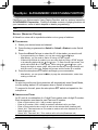
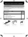
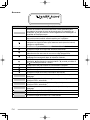
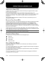
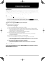
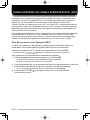
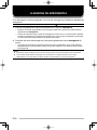
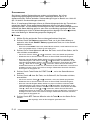
SUPPLIED ACCESSORIES
Item
Quantity
DC power cable
1
• Fuse (15 A) (2 pieces)
Mounting bracket
1
Screw set:
1
• Self-tapping screw (4 pieces)
• Hex-headed screw with washer (4 pieces)
• Spring washer (4 pieces)
• Flat washer (4 pieces)
Instruction manual
1
DC power cable
(with fuses)
Mounting bracket Screw set

2
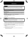
Various electronic equipment in your vehicle may malfunction if they are not properly protected
from the radio frequency energy which is present while transmitting. Electronic fuel injection, anti-
skid braking, and cruise control systems are typical examples of equipment that may malfunction.
If your vehicle contains such equipment, consult the dealer for the make of vehicle and enlist
his/her aid in determining if they will perform normally while transmitting.
Note: The following preparation instructions are for use by your Kenwood dealer, an authorized
Kenwood service facility, or the factory.
TOOLS REQUIRED
Note: Before installing the transceiver, always check how far the mounting screws will extend
below the mounting surface. When drilling mounting holes, be careful not to damage vehicle wiring
or parts.
The following tools are required for installing the transceiver:
• 1/14 inch (6 mm) or larger electric drill
• 5/32 inch (4.2 mm) drill bit for the self-tapping screws
• Circle cutters
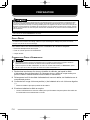
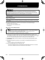
POWER CABLE CONNECTION
◆ The transceiver operates in 12 V negative ground systems only! Check the battery polarity and
voltage of the vehicle before installing the transceiver.
◆ Use only the supplied DC power cable or a Kenwood optional DC power cable.
◆ Do not cut and/or remove the fuse holder on the DC power cable.
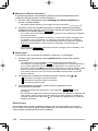
1 Check for an existing hole, conveniently located in the firewall, where the
power cable can be passed through. If no hole exists, use a circle cutter to
drill the firewall, then install a rubber grommet.
2 Run the two power cable leads through the firewall and into the engine
compartment, from the passenger compartment.
3 Connect the red lead to the positive (+) battery terminal and the black lead to
the negative (–) battery terminal.
• Locate the fuse as close to the battery as possible.
4 Coil and secure the surplus cable with a retaining band.
• Be sure to leave enough slack in the cables so the transceiver can be removed for
servicing while keeping the power applied.
PREPARATION

3
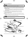
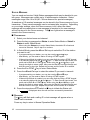
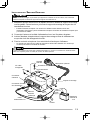
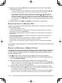
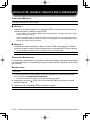
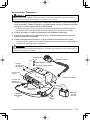
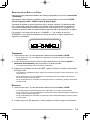
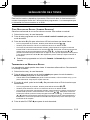
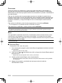
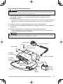
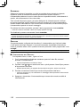
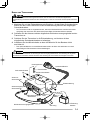
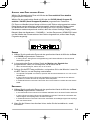
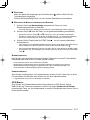
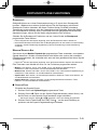
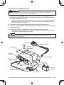
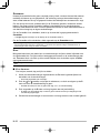
INSTALLING THE TRANSCEIVER
For passenger safety, install the transceiver securely using the supplied mounting bracket and
screw set so the transceiver will not break loose in the event of a collision.
1 Mark the position of the holes in the dash by using the mounting bracket as a
template. Drill the holes, then attach the mounting bracket using the supplied
self-tapping screws.
• Be sure to mount the transceiver in a location where the controls are within easy
reach of the user and where there is sufficient space at the rear of the transceiver for
cable connections.
2 Connect the antenna and the supplied power cable to the transceiver.
3 Slide the transceiver into the mounting bracket and secure it using the
supplied hex-headed screws.
4 Mount a microphone hanger in a location where it will be within easy reach of
the user.
• The optional microphone and microphone cable should be mounted in a place where
they will not interfere with the safe operation of the vehicle.
When replacing the fuse in the DC power cable, be sure to replace it with a fuse of the same value.
Never replace a fuse with a fuse that has a higher value.
Hex-headed
screws
DC power
cable
Mounting bracket
Antenna
connector
Power input
connector
Fuse
Black (–)
cable
Red (+)
cable
12 V vehicle
battery
Optional microphone
Self-tapping screw
Spring washer
Flat washer
Ignition
sense cable

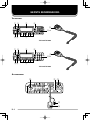
4
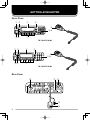
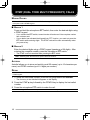
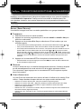
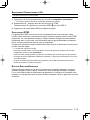
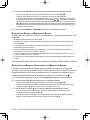
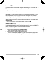
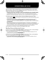
GETTING ACQUAINTED
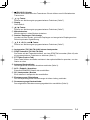
FRONT PANEL
qw e r
i a
o
ty
u
TK-7180/ TK-8180
1 2 3
4 5 6
7 8 9
0
#
qw e r
i b
o
ty
u
TK-7189/ TK-8189
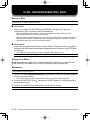
REAR PANEL
!
0
!
2
!3
!4
!
1

5
(Power) switch
Press to switch the transceiver ON. Press again to switch the transceiver
OFF.
/ keys
Press to activate their programmable functions {page 7}.
Display
Refer to page 6.
/ keys
Press to activate their programmable functions {page 7}.
Microphone jack
Insert the microphone plug into this jack.
Transmit/ Busy/ Call indicator
Lights red while transmitting, green while receiving, and orange while receiving
a call using optional signaling.
, S, A, <B, C>, ■ keys
Press to activate their programmable functions {page 7}.
a) Speaker (TK-7180/ TK-8180)
Internal speaker.
b) DTMF Keypad (TK-7189/ TK-8189)
Press the keys on the keypad to make DTMF calls {page 18} or to activate
their programmable functions {page 7}.
PTT (Push-to-Talk) switch
Press and hold this switch, then speak into the optional microphone to call a
station.
Antenna connector
Attach the vehicle antenna to this connector {page 3}.
ACC. (accessory) connector
Connect external KENWOOD accessories to this connector.
SP (speaker) jack
Connect an external speaker to this jack.
Ignition sense line
Connect the vehicle ignition sensor to this line.
Power input connector
Attach the supplied DC power cable to this connector {page 3}.

6
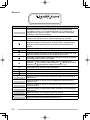
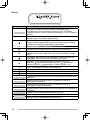
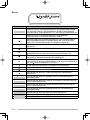
DISPLAY
Indicator Description
Displays the zone and channel numbers. Your dealer can
program zone and channel names with up to 12 characters,
in place of numbers. Also displays received 5-tone and
FleetSync messages.
Displays the zone and channel numbers. Also displays list
numbers for Operator Selectable Tones.
Displays the strength of received signals. An antenna and all
3 strength bars represents strong signals while the antenna
by itself (no strength bars) represents weak signals.
Appears when Monitor or Squelch Off is activated.
Appears when the Talk Around function has been activated.
Appears when you are using Scan mode or when the selected
zone is a Voting or Free Channel Call zone.
Flashes when you receive a message. Lights when a
message is stored in the queue memory.
Appears when the selected channel is programmed as
priority. represents Priority Channel 1, represents Priority
Channel 2, and represents Priority Channels 1 and 2.
This icon is not used on this transceiver.
Appears when the Horn Alert function is activated.
Appears when the Scrambler function is activated.
Appears when the Public Address function is activated.
Appears when the selected zone is added to the scanning
sequence.
Appears when the Auto Recording function on the VGS-1
option is activated.
Appears when an Auto Reply Message on the VGS-1 option
is activated.
Appears when the selected channel is added to the scanning
sequence.
Appears when the AUX A function has been activated.
Appears when the AUX B function has been activated.
Appears when the OST function has been activated.

7
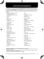
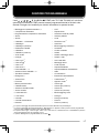
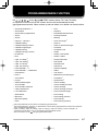
PROGRAMMABLE FUNCTIONS
The , , , , , S, A, <B, C>, ■, DTMF (TK-7189/ TK-8189 only) keys, and
optional microphone with DTMF keypad can be programmed with the functions
listed below. Please contact your dealer for further details on these functions.
• Auto Reply Message
1, 2
• Autodial
• Autodial Programming
• AUX A
• AUX B
• Call 1 ~ Call 6
• CH/GID Down
• CH/GID Down (Continuous)
• CH/GID Recall
• CH/GID Up
• CH/GID Up (Continuous)
• Channel Entry
• Clock
• Digit 1x Down
3
• Digit 10x Down
3
• Digit 1x Up
3
• Digit 10x Up
3
• Direct CH/GID 1 ~ 5
• Direct CH/GID 1 ~ 5 Select
• Display Character
• Emergency
4
• Fixed Volume
• Function
• GPS Position Display
• Home CH/GID
• Home CH/GID Select
• Horn Alert
• LCD Brightness
• Lone Worker
• Monitor
• Monitor Momentary
• None
• OST
• Playback
2
• Priority Channel Select
• Public Address
• Queue
• Receive Entry
3
• Scan
• Scan Delete/Add
• Scrambler
• Scrambler Code
• Selcall
• Selcall + Short Messagel
• Selcall + Status
• Send the GPS data
• Short Message
• Squelch Level
• Squelch Off
• Squelch Off Momentary
• Status
• Talk Around
• Transceiver Password
• Transfer
3
• Voice Memo
2
• Volume Down
• Volume Down (Continuous)
• Volume Up
• Volume Up (Continuous)
• Zone Delete/Add
• Zone Down
• Zone Down (Continuous)
• Zone Up
• Zone Up (Continuous)
1
“Auto Reply Message” can be used only for FleetSync.
2
“Auto Reply Message”, “Playback”, and “Voice Memo” can be programmed only when the optional
VGS-1 board has been installed.
3
“Digit 1x Down”, “Digit 10x Down”, “Digit 1x Up”, “Digit 10x Up”, “Receive Entry”, and “Transfer” can
be programmed only for 5-tone calls.
4
“Emergency” can be programmed only on the key.

8
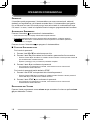
BASIC OPERATIONS
OVERVIEW
Your dealer can program your transceiver with Conventional, Voting, Voting with
Signaling, and Free Channel Call zones. The transceiver can handle up to 128
zones with up to 250 channels in each zone and a total combined maximum of
512 channels. Zones, channels, and their functions are programmed by your
dealer.
SWITCHING POWER ON/ OFF
Press the switch to switch the transceiver ON.
• A beep sounds and the display momentarily lights up.
• If the Transceiver Password function is programmed, “
” appears on the
display. You must enter the password to unlock the transceiver. Refer to “Transceiver
Password”, below.
Press the switch again to switch the transceiver OFF.
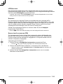
■ TRANSCEIVER PASSWORD
To enter the password:
1 Press the and keys to select a digit.
2 Press the C> key to accept the entered digit and move to the next digit.
• Press the A key to delete an incorrect character. Press and hold the A key to
delete all entered characters.
• Repeat steps 1 and 2 to enter the entire password.
3 Press the S key to confirm the password.
• If you enter an incorrect password, an error tone sounds and the transceiver
remains locked.
To enter the password using a DTMF keypad:
1 Press the DTMF keys corresponding to the password digits.
• Press the DTMF # key to delete an incorrect character. Press and hold the
DTMF # key to delete all entered characters.
2 Press the DTMF key to confirm the password.
• If you enter an incorrect password, an error tone sounds and the transceiver
remains locked.
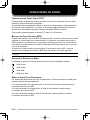
ADJUSTING THE VOLUME
Press the key programmed as Volume Up to increase the volume and Volume
Down to decrease the volume.

9
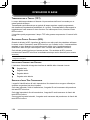
SELECTING A ZONE AND CHANNEL
Select the desired zone using the keys programmed as Zone Up and Zone
Down.
Select the desired channel using the keys programmed as CH/GID (Channel/
Group ID) Up and CH/GID (Channel/ Group ID) Down.
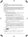
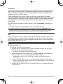
Names can be programmed for zones and channels with up to 12 characters
each. However, to fit on the display, names will be abbreviated. Your dealer
can set the zone name to a length of 0 to 12 digits. Channel names will shorten
appropriately, to fit in the 12-digit display.
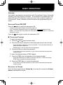
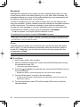
For example, if the channel name is “–CHANNEL1–” and the zone name is
“KENWOOD”, and your dealer sets the zone name to 3-digits, the following
display will appear:
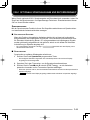
TRANSMITTING
1 Select the desired zone and channel using the Zone and CH/GID keys.
• In Voting, Voting with Signaling, and Free Channel Call zones, the channel is
selected automatically.
2 In Conventional zones, press the key programmed as Monitor or Squelch Off
to check whether or not the channel is free.
• If the channel is busy, wait until it becomes free.
3 Press microphone PTT switch and speak into the microphone. Release the
PTT switch to receive.
• For best sound quality at the receiving station, hold the microphone approximately
1.5 inches (3 ~ 4 cm) from your mouth.
• In Voting and Voting with Signaling zones, the transceiver will search for the closest
repeater and transmit using that repeater’s frequency.
• In Free Channel Call zones, the transceiver will search for a free channel and will
begin transmitting on that channel.
RECEIVING
1 Select the desired zone and channel using the Zone and CH/GID keys.
• Alternatively, in Conventional zones, you can activate the Scan function if desired.
• In Voting and Voting with Signaling zones, the transceiver will automatically search
for the strongest signal and receive on that frequency.
• In Free Channel Call zones, the transceiver will automatically search for any signal
and will receive on that channel.
2 When you hear a caller’s voice, readjust the volume as necessary.

10
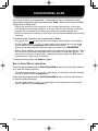
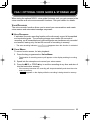
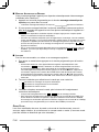
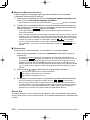
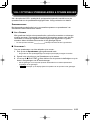
CONVENTIONAL SCAN
If the Scan function is programmed, Conventional zones or channels can be
scanned by pressing the key programmed as Scan. Scan can be used as either
Single Scan or Multi Scan.
• Single Scan monitors only the channels of the currently selected zone, which have
been added to the scanning sequence. If set up to scan Priority channels, the Priority
channels will be scanned even if they are not within the currently selected zone.
• Multi Scan monitors all channels of every zone, which have been added to the scanning
sequence.
To activate Scan, press the key programmed as Scan.
• The icon and “ ” or the revert zone and channel number appear on the display.
• The zone add indicator (
) will appear on the display when the selected
zone is added to the scan sequence. The channel add indicator (
) will
appear on the display when the selected channel is added to the scan sequence.
• When a call is received, scanning stops and the zone and channel digits appear. Press
the microphone PTT switch and speak into the microphone to respond to the call. The
transceiver will continue scanning after a predetermined time delay if the PTT switch is
released and no further signal is received.
To stop scanning, press the Scan key again.
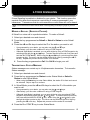
ADD TO SCAN/ DELETE FROM SCAN
Press the key programmed as Scan Delete/Add to add or remove each channel
to or from the scan sequence.
• The channel add indicator ( ) will appear on the display when the selected
channel is added to the scan sequence.
Press the key programmed as Zone Delete/Add to add or remove each zone to
or from the scan sequence.
• The zone add indicator ( ) will appear on the display when the selected
zone is added to the scan sequence.

11
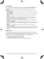
SCAN REVERT
You can select Revert zones and channels using the Zone and CH/GID keys.
Eight types of Scan Reverts which can be programmed by your dealer are
available.
• Last Called Revert: The last zone/ channel received is assigned as the new revert
zone and channel.
• Last Used Revert: The last zone/ channel responded to is assigned as the new revert
zone and channel.
• Selected: The last zone/ channel selected is assigned as the new revert zone and
channel.
• Selected + Talkback: If the zone/ channel has been changed during Scan, the
newly selected zone/ channel is assigned as the new revert zone and channel. The
transceiver “talks back” on the current receive channel.
• Priority 1: If your dealer has programmed a Priority 1 channel, this channel is the
revert zone and channel.
• Priority 1 + Talkback: If your dealer has programmed a Priority 1 channel, this channel
is the revert zone and channel. The transceiver “talks back” on the current receive
channel.
• Priority 2: If your dealer has programmed a Priority 2 channel, this channel is the
revert zone and channel.
• Priority 2 + Talkback: If your dealer has programmed a Priority 2 channel, this channel
is the revert zone and channel. The transceiver “talks back” on the current receive
channel.
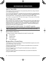
PRIORITY SCAN
A Priority channel must be programmed in order for Priority Scan to function.
The transceiver will automatically change to the Priority channel when a signal is
received on it, even if a signal is being received on a normal channel.
• The indicator represents the Priority 1 channel.
• The
indicator represents the Priority 2 channel.
• The
indicator represents both the Priority 1 and Priority 2 channel.

12
QUIET TALK (QT)/ DIGITAL QUIET TALK (DQT)
Your dealer may have programmed QT or DQT signaling on your transceiver
channels. A QT tone/ DQT code is a sub-audible tone/code which allows you to
ignore (not hear) calls from other parties who are using the same channel.
When a channel is set up with a QT tone or DQT code, squelch will open only
when a call containing a matching tone or code is received. Likewise, signals that
you transmit will be heard only by parties whose QT/ DQT signaling matches your
transceiver.
If a call containing a different tone or code is made on the same channel you are
using, squelch will not open and you will not hear the call. Although it may seem
like you have your own private channel while using QT/ DQT, other parties can
still hear your calls if they set up their transceiver with the same tone or code.
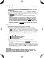
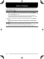
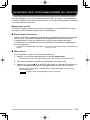
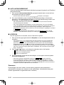
OPERATOR SELECTABLE TONE (OST)
You can change the preset encode and decode tones for the selected channel.
Your dealer can program up to 40 tones on your transceiver.
To turn OST on or off, press the key programmed as OST.
• The OST indicator ( ) appears on the display when this function is
activated.
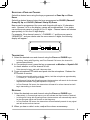
To change the preset encode/decode tones:
1 Press and hold the key programmed as OST.
• The duration for holding the OST key is programmed by your dealer.
• The OST number and name appear on the display.
2 Press the <B and C> keys or enter the list number directly using a DTMF
keypad to select your desired encode/decode pair.
• If programmed by your dealer, you can also use the and keys.
3 Press the S or DTMF key to accept the new setting and return to normal
operation.
La pagina si sta caricando...
La pagina si sta caricando...
La pagina si sta caricando...
La pagina si sta caricando...
La pagina si sta caricando...
La pagina si sta caricando...
La pagina si sta caricando...
La pagina si sta caricando...
La pagina si sta caricando...
La pagina si sta caricando...
La pagina si sta caricando...
La pagina si sta caricando...
La pagina si sta caricando...
La pagina si sta caricando...
La pagina si sta caricando...
La pagina si sta caricando...
La pagina si sta caricando...
La pagina si sta caricando...
La pagina si sta caricando...
La pagina si sta caricando...
La pagina si sta caricando...
La pagina si sta caricando...
La pagina si sta caricando...
La pagina si sta caricando...
La pagina si sta caricando...
La pagina si sta caricando...
La pagina si sta caricando...
La pagina si sta caricando...
La pagina si sta caricando...
La pagina si sta caricando...
La pagina si sta caricando...
La pagina si sta caricando...
La pagina si sta caricando...
La pagina si sta caricando...
La pagina si sta caricando...
La pagina si sta caricando...
La pagina si sta caricando...
La pagina si sta caricando...
La pagina si sta caricando...
La pagina si sta caricando...
La pagina si sta caricando...
La pagina si sta caricando...
La pagina si sta caricando...
La pagina si sta caricando...
La pagina si sta caricando...
La pagina si sta caricando...
La pagina si sta caricando...
La pagina si sta caricando...
La pagina si sta caricando...
La pagina si sta caricando...
La pagina si sta caricando...
La pagina si sta caricando...
La pagina si sta caricando...
La pagina si sta caricando...
La pagina si sta caricando...
La pagina si sta caricando...
La pagina si sta caricando...
La pagina si sta caricando...
La pagina si sta caricando...
La pagina si sta caricando...
La pagina si sta caricando...
La pagina si sta caricando...
La pagina si sta caricando...
La pagina si sta caricando...
La pagina si sta caricando...
La pagina si sta caricando...
La pagina si sta caricando...
La pagina si sta caricando...
La pagina si sta caricando...
La pagina si sta caricando...
La pagina si sta caricando...
La pagina si sta caricando...
La pagina si sta caricando...
La pagina si sta caricando...
La pagina si sta caricando...
La pagina si sta caricando...
La pagina si sta caricando...
La pagina si sta caricando...
La pagina si sta caricando...
La pagina si sta caricando...
La pagina si sta caricando...
La pagina si sta caricando...
La pagina si sta caricando...
La pagina si sta caricando...
La pagina si sta caricando...
La pagina si sta caricando...
La pagina si sta caricando...
La pagina si sta caricando...
La pagina si sta caricando...
La pagina si sta caricando...
La pagina si sta caricando...
La pagina si sta caricando...
La pagina si sta caricando...
La pagina si sta caricando...
La pagina si sta caricando...
La pagina si sta caricando...
La pagina si sta caricando...
La pagina si sta caricando...
La pagina si sta caricando...
La pagina si sta caricando...
La pagina si sta caricando...
La pagina si sta caricando...
La pagina si sta caricando...
La pagina si sta caricando...
La pagina si sta caricando...
La pagina si sta caricando...
La pagina si sta caricando...
La pagina si sta caricando...
La pagina si sta caricando...
La pagina si sta caricando...
La pagina si sta caricando...
La pagina si sta caricando...
La pagina si sta caricando...
La pagina si sta caricando...
La pagina si sta caricando...
La pagina si sta caricando...
La pagina si sta caricando...
La pagina si sta caricando...
La pagina si sta caricando...
La pagina si sta caricando...
La pagina si sta caricando...
La pagina si sta caricando...
La pagina si sta caricando...
La pagina si sta caricando...
La pagina si sta caricando...
La pagina si sta caricando...
La pagina si sta caricando...
La pagina si sta caricando...
La pagina si sta caricando...
La pagina si sta caricando...
La pagina si sta caricando...
La pagina si sta caricando...
La pagina si sta caricando...
La pagina si sta caricando...
La pagina si sta caricando...
La pagina si sta caricando...
La pagina si sta caricando...
La pagina si sta caricando...
La pagina si sta caricando...
La pagina si sta caricando...
La pagina si sta caricando...
La pagina si sta caricando...
La pagina si sta caricando...
La pagina si sta caricando...
La pagina si sta caricando...
La pagina si sta caricando...
La pagina si sta caricando...
La pagina si sta caricando...
La pagina si sta caricando...
La pagina si sta caricando...
La pagina si sta caricando...
La pagina si sta caricando...
La pagina si sta caricando...
La pagina si sta caricando...
La pagina si sta caricando...
La pagina si sta caricando...
La pagina si sta caricando...
La pagina si sta caricando...
La pagina si sta caricando...
La pagina si sta caricando...
La pagina si sta caricando...
La pagina si sta caricando...
La pagina si sta caricando...
La pagina si sta caricando...
La pagina si sta caricando...
La pagina si sta caricando...
La pagina si sta caricando...
La pagina si sta caricando...
La pagina si sta caricando...
La pagina si sta caricando...
La pagina si sta caricando...
La pagina si sta caricando...
La pagina si sta caricando...
La pagina si sta caricando...
La pagina si sta caricando...
La pagina si sta caricando...
-
 1
1
-
 2
2
-
 3
3
-
 4
4
-
 5
5
-
 6
6
-
 7
7
-
 8
8
-
 9
9
-
 10
10
-
 11
11
-
 12
12
-
 13
13
-
 14
14
-
 15
15
-
 16
16
-
 17
17
-
 18
18
-
 19
19
-
 20
20
-
 21
21
-
 22
22
-
 23
23
-
 24
24
-
 25
25
-
 26
26
-
 27
27
-
 28
28
-
 29
29
-
 30
30
-
 31
31
-
 32
32
-
 33
33
-
 34
34
-
 35
35
-
 36
36
-
 37
37
-
 38
38
-
 39
39
-
 40
40
-
 41
41
-
 42
42
-
 43
43
-
 44
44
-
 45
45
-
 46
46
-
 47
47
-
 48
48
-
 49
49
-
 50
50
-
 51
51
-
 52
52
-
 53
53
-
 54
54
-
 55
55
-
 56
56
-
 57
57
-
 58
58
-
 59
59
-
 60
60
-
 61
61
-
 62
62
-
 63
63
-
 64
64
-
 65
65
-
 66
66
-
 67
67
-
 68
68
-
 69
69
-
 70
70
-
 71
71
-
 72
72
-
 73
73
-
 74
74
-
 75
75
-
 76
76
-
 77
77
-
 78
78
-
 79
79
-
 80
80
-
 81
81
-
 82
82
-
 83
83
-
 84
84
-
 85
85
-
 86
86
-
 87
87
-
 88
88
-
 89
89
-
 90
90
-
 91
91
-
 92
92
-
 93
93
-
 94
94
-
 95
95
-
 96
96
-
 97
97
-
 98
98
-
 99
99
-
 100
100
-
 101
101
-
 102
102
-
 103
103
-
 104
104
-
 105
105
-
 106
106
-
 107
107
-
 108
108
-
 109
109
-
 110
110
-
 111
111
-
 112
112
-
 113
113
-
 114
114
-
 115
115
-
 116
116
-
 117
117
-
 118
118
-
 119
119
-
 120
120
-
 121
121
-
 122
122
-
 123
123
-
 124
124
-
 125
125
-
 126
126
-
 127
127
-
 128
128
-
 129
129
-
 130
130
-
 131
131
-
 132
132
-
 133
133
-
 134
134
-
 135
135
-
 136
136
-
 137
137
-
 138
138
-
 139
139
-
 140
140
-
 141
141
-
 142
142
-
 143
143
-
 144
144
-
 145
145
-
 146
146
-
 147
147
-
 148
148
-
 149
149
-
 150
150
-
 151
151
-
 152
152
-
 153
153
-
 154
154
-
 155
155
-
 156
156
-
 157
157
-
 158
158
-
 159
159
-
 160
160
-
 161
161
-
 162
162
-
 163
163
-
 164
164
-
 165
165
-
 166
166
-
 167
167
-
 168
168
-
 169
169
-
 170
170
-
 171
171
-
 172
172
-
 173
173
-
 174
174
-
 175
175
-
 176
176
-
 177
177
-
 178
178
-
 179
179
-
 180
180
-
 181
181
-
 182
182
-
 183
183
-
 184
184
-
 185
185
-
 186
186
-
 187
187
-
 188
188
-
 189
189
-
 190
190
-
 191
191
-
 192
192
-
 193
193
-
 194
194
-
 195
195
-
 196
196


Kenwood TK-7189 Manuale utente
- Tipo
- Manuale utente
in altre lingue
- English: Kenwood TK-7189 User manual
- français: Kenwood TK-7189 Manuel utilisateur
- español: Kenwood TK-7189 Manual de usuario
- Deutsch: Kenwood TK-7189 Benutzerhandbuch
- Nederlands: Kenwood TK-7189 Handleiding
Documenti correlati
-
Kenwood TK-2180 Manuale utente
-
-
Kenwood NX-5000 Manuale utente
-
Kenwood TH-F6A Manuale utente
-
Kenwood TM-701A Manuale utente
-
-
-
-
-
