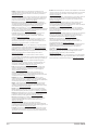
Asus N100I-EM-A Manuale utente
- Categoria
- Schede madri
- Tipo
- Manuale utente

Industrial Motherboard
N100I-EM-A

ii
E22109
First Edition
August 2023
Copyright © 2023 ASUSTeK COMPUTER INC. All Rights Reserved.
No part of this manual, including the products and software described in it, may be reproduced,
transmitted, transcribed, stored in a retrieval system, or translated into any language in any form or by any
means, except documentation kept by the purchaser for backup purposes, without the express written
permission of ASUSTeK COMPUTER INC. (“ASUS”).
Product warranty or service will not be extended if: (1) the product is repaired, modied or altered, unless
such repair, modication of alteration is authorized in writing by ASUS; or (2) the serial number of the
product is defaced or missing.
ASUS PROVIDES THIS MANUAL “AS IS” WITHOUT WARRANTY OF ANY KIND, EITHER EXPRESS
OR IMPLIED, INCLUDING BUT NOT LIMITED TO THE IMPLIED WARRANTIES OR CONDITIONS OF
MERCHANTABILITY OR FITNESS FOR A PARTICULAR PURPOSE. IN NO EVENT SHALL ASUS, ITS
DIRECTORS, OFFICERS, EMPLOYEES OR AGENTS BE LIABLE FOR ANY INDIRECT, SPECIAL,
INCIDENTAL, OR CONSEQUENTIAL DAMAGES (INCLUDING DAMAGES FOR LOSS OF PROFITS,
LOSS OF BUSINESS, LOSS OF USE OR DATA, INTERRUPTION OF BUSINESS AND THE LIKE),
EVEN IF ASUS HAS BEEN ADVISED OF THE POSSIBILITY OF SUCH DAMAGES ARISING FROM ANY
DEFECT OR ERROR IN THIS MANUAL OR PRODUCT.
SPECIFICATIONS AND INFORMATION CONTAINED IN THIS MANUAL ARE FURNISHED FOR
INFORMATIONAL USE ONLY, AND ARE SUBJECT TO CHANGE AT ANY TIME WITHOUT NOTICE,
AND SHOULD NOT BE CONSTRUED AS A COMMITMENT BY ASUS. ASUS ASSUMES NO
RESPONSIBILITY OR LIABILITY FOR ANY ERRORS OR INACCURACIES THAT MAY APPEAR IN THIS
MANUAL, INCLUDING THE PRODUCTS AND SOFTWARE DESCRIBED IN IT.
Products and corporate names appearing in this manual may or may not be registered trademarks or
copyrights of their respective companies, and are used only for identication or explanation and to the
owners’ benet, without intent to infringe.

iii
Contents
Chapter 1 Product overview
1.1 Package contents ......................................................................... 1-1
1.2 Features ........................................................................................ 1-1
1.3 Specications ............................................................................... 1-2
Chapter 2 Motherboard information
2.1 Before you proceed ..................................................................... 2-1
2.2 Motherboard layout ...................................................................... 2-2
2.3 Central Processing Unit (CPU) ................................................... 2-4
2.4 System memory ........................................................................... 2-4
2.4.1 Installing a DIMM ............................................................ 2-5
2.5 Jumpers ........................................................................................ 2-6
2.6 Connectors ................................................................................. 2-11
2.6.1 Rear panel connectors .................................................. 2-11
2.6.2 Internal connectors ....................................................... 2-13
2.7 Slot .............................................................................................. 2-24
Chapter 3 BIOS setup
3.1 BIOS Setup program .................................................................... 3-1
3.2 Main menu .................................................................................... 3-2
3.2.1 System Date [Day MM/DD/YYYY] .................................. 3-2
3.2.2 System Time [HH:MM:SS] .............................................. 3-2
3.3 Advanced menu ........................................................................... 3-2
3.3.1 LVDS Conguration ........................................................ 3-2
3.3.2 PCH-FW Conguration ................................................... 3-4
3.3.3 Trusted Computing ......................................................... 3-4
3.3.4 CPU Conguration .......................................................... 3-5
3.3.5 Graphics Conguration ................................................... 3-6
3.3.6 PCI Express Conguration .............................................. 3-6
3.3.7 Super IO Conguration ................................................... 3-7
3.3.8 Serial Console Redirection ............................................. 3-8
3.3.9 SATA Conguration ........................................................ 3-9
3.3.10 Network Stack Conguration ........................................ 3-10
3.3.11 USB Conguration ........................................................ 3-10
3.3.12 NVMe Conguration ...................................................... 3-11
3.3.13 Onboard Devices Conguration .................................... 3-11

iv
3.3.14 Miscellaneous ............................................................... 3-12
3.3.15 APM Conguration ........................................................ 3-12
3.3.16 EZ-Flash ....................................................................... 3-13
3.3.17 Watchdog Timer ............................................................ 3-13
3.4 Hardware Monitor menu ............................................................ 3-14
Smart Fan Mode .......................................................................... 3-14
Smart Fan Function ...................................................................... 3-14
3.5 Security menu ............................................................................ 3-14
3.5.1 Administrator Password ................................................ 3-14
3.5.2 User Password .............................................................. 3-15
3.5.3 Secure Boot .................................................................. 3-15
3.6 Boot menu .................................................................................. 3-16
3.7 Exit menu .................................................................................... 3-16
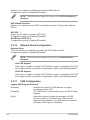
Appendix
Notices .......................................................................................................A-1

1-1
Chapter 1: General information
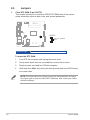
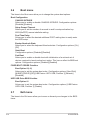
1.1 Package contents
Check your industrial motherboard package for the following items.
1 x ASUS N100I-EM-A Motherboard
1 x Serial ATA 6.0 Gb/s cable
2 x M.2 screw packages
1 x ASUS I/O Shield
NOTE: If any of the above items is damaged or missing, contact your
distributor or sales representative immediately.
1.2 Features
• Built-in Intel® Celeron® Quad-core Processor N100
• One DDR4 3200/3000/2800/2666/2400/2133 MHz Non-ECC SO-DIMM up to
16GB
• 2 x SATA 6Gb/s ports, 4 x USB 3.2 Gen 1 headers, 3 x USB 2.0 headers, 3 x
COM headers, 3 x COM connectors
• 1 x PCIe 3.0/2.0 x 1 slot (x1 mode), 1 x M.2 socket (E key) , 1 x M.2 socket (M
key)
• Multi-display: 1 x VGA port, 1 x HDMI™ port, 1 x LVDS connector
Chapter 1
Product overview

N100I-EM-A
1-2
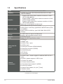
1.3 Specications
(continued on the next page)
CPU Built-in Intel® Celeron® Quad-core Processor N100
Memory 1 x DDR4, max.16GB, 3200/3000/2800/2666/2400/2133 MHz
Non-ECC Memory
Graphics
- Supports VGA output with a maximum resolution of 1920 x
1200 @ 60Hz (Default)
- Supports HDMITM output with a maximum resolution of 3840
x 2160 @ 60Hz (Default)
- Supports LVDS output with a maximum resolution of 1920 x
1200 @ 60Hz (Default)
Support up to three displays simultaneously
Expansion slots
1 x PCI Express 3.0/2.0 x1 slot (x1 mode)
1 x M.2 Socket 1 with E key, type 2230 for WIFI/BT device (PCIe
x1 /USB2.0)
1 x M.2 Socket 3 with M key, type 2242/ 2260/ 2280 (SATA/
PCIex1)
Storage
2 x SATA Gen 3.0 up to 6.0 Gb/s ports
*SATA6G_2 shares bandwidth with M.2 socket 3.
Ethernet 2 x Realtek® 8111H
Audio Realtek® ALC897 High Denition Audio
Rear panel I/O
ports
1 x VGA port
1 x HDMITM port
2 x USB 3.2 Gen 1 ports
2 x USB 2.0 ports
1 x Serial Port connector (RS232/422/485)
2 x Serial Port connectors (RS232)
2 x LAN (RJ45) ports
1 x DC-IN port
2 x Audio jacks
Internal
Connectors
1 x USB 3.2 Gen 1 header supports 2 additional USB 3.2 Gen 1
ports
1 x USB 2.0 header supports 1 USB 2.0 port
1 x Chassis Fan header
1 x Chassis Intrusion header
1 x Front Panel Audio header (F_AUDIO)
3 x Serial Port headers
1 x System Panel header (10-1 pin F_Panel)
1 x Speaker header
1 x Stereo Out header

1-3
Chapter 1: General information
Internal
Connectors
1 x Clear CMOS header
1 x COM Debug header
1 x GPIO connector
1 x LVDS Signal header
1 x LCD Panel Monitor Switch header
1 x LVDS Panel VCC Power Selection jumper
1 x LVDS Panel Backlight Enable Signal Selection jumper
1 x LVDS Backlight Panel header
1 x 4-pin ATX power connector (DC in mode)
Watchdog Timer Yes
Security 1 x SPI TPM header
Manageability WfM 2.0, WOL by PME
Power
requirement 12v DC-IN
Operation
Temperature 0~60°C
Non-Operation
Temperature -40~85°C
Relative Humidity Operational humidity: 40°C@10%~95%
OS support Windows® 10 (64bit) / Windows® IoT enterprise
Ubuntu, RedHat Enterprise, Fedora Workstation, OpenSUSE
Form Factor Mini-ITX Form Factor, 17.0cm x 17.0cm
NOTE: Specications are subject to change without notice.

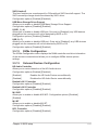
2-1
Chapter 2: Motherboard information
Chapter 2
Motherboard information
2.1 Before you proceed
Take note of the following precautions before you install motherboard components
or change any motherboard settings.
CAUTION!
• Unplug the power cord from the wall socket before touching any
component.
• Before handling components, use a grounded wrist strap or touch a safely
grounded object or a metal object, such as the power supply case, to avoid
damaging them due to static electricity.
• Hold components by the edges to avoid touching the ICs on them.
• Whenever you uninstall any component, place it on a grounded antistatic
pad or in the bag that came with the component.
• Before you install or remove any component, always remove the AC power
by unplugging the power cord from the power outlet. Failure to do so may
cause severe damage to the motherboard, peripherals, or components.

N100I-EM-A
2-2
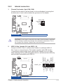
17.0cm(6.7in)
17.0cm(6.7in)
AT_ATX_SEL
F_AUDIOAUDIO
Super
I/O
(BOTTOM)
256Mb
BIOS
M.2_(SOCKET3)
M.2(WIFI)
GPIO_CON
BATTERY
CLRTC
USB_7
TPM
SATA_PWR2 SATA_PWR1
SPEAKER
CHASSIS F_PANEL
COM4 COM5
22602280 2242
COM6
CHA_FAN
VCC_PWR SEL
DC_PWR1
DC_PWR2
COM2
HDMI
COM3
VGA
COM1
COM1_SEL
LAN1_USB_56
LAN2_U32G1_12
DDR4 So-DIMM_A (64bit, 204-pin module)
SATA6G_2SATA6G_1
PCIEX1(G3)
I2C
COM_DEBUG
Intel®
N100
ALC
897
RTL
8111H
RTL
8111H
PANEL_SW
BKLTEN_SEL
SPK_OUT
LVDS_EDP
LCD_BLKT_PANEL
U32G1_34
13
12
14
9
11
10
7
8
6
18 17 16 15
20 19
23 22
24 21
29
30
28
27
26
25
1 52 43
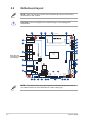
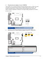
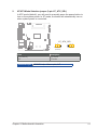
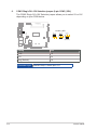
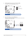
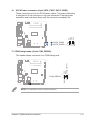
2.2 Motherboard layout
Place this side
towards the rear
of the chassis
NOTE: Place four screws into the holes indicated by circles to secure the
motherboard to the chassis.
CAUTION! Do not overtighten the screws! Doing so can damage the
motherboard.
NOTE: The audio codec may vary between motherboards, please consult
your sales window for the motherboards’ exact codec type.

2-3
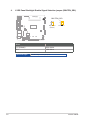
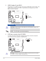
Chapter 2: Motherboard information
Connectors/Jumpers/Slots Page
1. ATX Power connector (4-pin DC_PWR2) 2-14
2. USB 3.2 Gen 1 header (20-1 pin U32G1_34) 2-13
3. Built-in Intel® Celeron® Quad-core Processor N100 2-4
4. DDR4 SO-DIMM slot 2-4
5. LVDS Panel Backlight Enable Signal Selection jumper (3-pin BKLTEN_SEL) 2-8
6. LCD Panel Monitor Switch header (2-pin PANEL_SW) 2-18
7. LVDS Backlight Panel header (5-pin LCD_BLKT_PANEL) 2-17
8. LVDS Panel VCC Power Selection jumper (6-pin VCC_PWR_SEL) 2-7
9. Chassis Fan header (4-pin CHA_FAN) 2-13
10. Clear RTC RAM (2-pin CLRTC) 2-6
11. LVDS Signal header (40-pin LVDS_EDP) 2-18
12. M.2 socket 3 2-15
13. SATA ports (7-pin SATA6G_1, SATA6G_2) 2-17
14. SATA Power connectors (4-pin SATA_PWR1, SATA_PWR2) 2-21
15. System Panel header (10-1 pin F_PANEL) 2-16
16. Chassis Intrusion header (4-1 pin CHASSIS) 2-13
17. Speaker header 2-23
18. Serial Port headers (10-1 pin COM4-6) 2-20
19. General Purpose Input/Output connector (10-pin GPIO_CON) 2-23
20. COM Debug header (6-1 pin COM_DEBUG) 2-21
21. PCI Express x1 slot 2-24
22. AT/ATX Mode Selection jumper (3-pin AT_ATX_SEL) 2-9
23. Stereo Speaker header (4-pin SPK_OUT) 2-19
24. I2C header (6-1 pin I2C) 2-22
25. Front Panel Audio header (10-1 pin F_AUDIO) 2-19
26. RTC Battery connector 2-22
27. TPM header (14-1 pin TPM) 2-20
28. COM1 Ring/+5V/+12V Selection jumper (6-pin COM1_SEL) 2-10
29. USB 2.0 header (5-1 pin USB_7) 2-14
30. M.2 Wi-Fi 2-15

N100I-EM-A
2-4
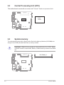
2.3 Central Processing Unit (CPU)
The motherboard comes with an onboard Intel® Celeron® Quad-core processor N100.
Intel®
N100
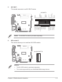
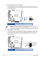
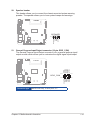
2.4 System memory
The motherboard comes with a Small Outline Dual Inline Memory Modules (SO-DIMM) slot
designed for a DDR4 (Double Data Rate 4) memory module.
CAUTION! A DDR4 memory module is notched differently from a DDR, DDR2,
or DDR3. DO NOT install a DDR, DDR2, or DDR3 memory module to the DDR5
slot.
SO-DIMM_A

2-5
Chapter 2: Motherboard information
To remove a DIMM
2.4.1 Installing a DIMM
3
3

N100I-EM-A
2-6
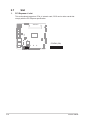
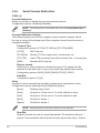
2.5 Jumpers
1. Clear RTC RAM (2-pin CLRTC)
This header allows you to clear the CMOS RTC RAM data of the system
setup information such as date, time, and system passwords.
To erase the RTC RAM:
1. Turn OFF the computer and unplug the power cord.
2. Use a metal object such as a screwdriver to short the two pins.
3. Plug the power cord and turn ON the computer.
4. Hold down the <Del> key during the boot process and enter BIOS setup
to re-enter data.
NOTE: If the steps above do not help, remove the onboard battery and move
the jumper again to clear the CMOS RTC RAM data. After clearing the CMOS,
reinstall the battery.
+3V_BAT_NOTEST
GND
CLRTC
PIN 1
Connector type
HEADER 1x2p, 2.54mm pitch, S/T

2-7
Chapter 2: Motherboard information
2. Chassis intrusion header (4-1 pin_CHASSIS)
This header is for a chassis-mounted intrusion detection sensor or switch. Connect
one end of the chassis intrusion sensor or switch cable to this connector. The
chassis intrusion sensor or switch sends a low-level signal to this connector
when a chassis component is installed. The signal is then generated as a chassis
intrusion event.
+5VSB_ATX
O_CASEOPEN
GND
CHASSIS
PIN 1
Connector type
HEADER 4p, K2, 2.54mm pitch
Setting Pins
3V (Default) 1-2
5V 3-4
12V 5-6
3. LVDS Panel VCC Power Selection jumper (6-pin VCC_PWR_SEL)
12V5V
1
3V
(Default)
VCC_PWR_SEL
3
4
5
6
2
Connector type
HEADER 2 x 3p, 2.54mm pitch, S/T

N100I-EM-A
2-8
4. LVDS Panel Backlight Enable Signal Selection jumper (BKLTEN_SEL)
Pins
1-2 (Default) High Active
2-3 Low Active
1 2
2 3
High Active
(Default)
Low Active
BKLTEN_SEL
Connector type
HEADER 1x3p, 2.54mm pitch, S/T

2-9
Chapter 2: Motherboard information
5. AT/ATX Mode Selection jumper (3-pin AT_ATX_SEL)
In ATX mode (default), you will need to manually press the power button to
turn on the system power. In AT mode, the board will automatically turn on
when system power is connected.
Connector type HEADER 1x3p, 2.54mm pitch, S/T
21 2 3
ATX MODE
(Default)
AT MODE
AT_ATX_SEL
Pins Description
1-2 (Default) ATX mode
2-3 AT mode

N100I-EM-A
2-10
6. COM1 Ring/+5V/+12V Selection jumper (6-pin COM1_SEL)
The COM1 Ring/+5V/+12V Selection jumper allows you to select 5V or 12V
depending on your COM device.
Setting Pins
+12V 1-2
+5V 3-4
Ring (Default) 5-6
COM1_SEL
RI
(Default)
+5V+12V
12 34 56
Connector type HEADER 2x3p, 2.54mm pitch, S/T

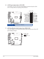
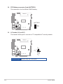
2-11
Chapter 2: Motherboard information
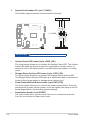
2.6 Connectors
2.6.1 Rear panel connectors
3
1 2 5
9
4
7 863
1. DC Power connector. Insert the power adapter into this port.
NOTES:
• It only supports 12V DC input.
• The power adapter is purchased separately.
2. HDMI™ port. This port is for a High-Denition Multimedia Interface (HDMI™)
connector, and is HDCP compliant allowing playback of HD DVD, Blu-ray,
and other protected content.
3. Serial port connectors (COM). These ports connect modems, or other
devices that conform with serial specication.
4. LAN (RJ-45) ports. These ports allow Gigabit connection to a Local Area
Network (LAN) through a network hub.
LAN port LED indications
LAN port
Speed
LED
Activity Link
LED
Activity/Link LED Speed LED
Status Description Status Description
Off No link OFF 10Mbps connection
Orange Linked ORANGE 100Mbps connection
Orange (Blinking) Data activity GREEN 1Gbps connection
Orange (Blinking
then steady)
Ready to wake
up from S5 mode
5. Line Out port (lime). This port connects to a headphone or a speaker. In
the 4, and 5.1 channel congurations, the function of this port becomes Front
Speaker Out.

N100I-EM-A
2-12
6. Video Graphics Adapter (VGA) port. This 15-pin port is for a VGA monitor
or other VGA-compatible devices.
7. USB 3.2 Gen 1 (up to 5Gbps) ports (blue, Type-A). These Universal Serial
Bus (USB) ports are for USB 3.2 Gen 1 devices.
NOTE: We strongly recommend that you connect USB 3.2 Gen 1 devices to
USB 3.2 Gen 1 ports for faster and better performance from your USB 3.2 Gen
1 devices.
8. USB 2.0 ports. These Universal Serial Bus (USB) ports are for USB 2.0/1.1
devices.
9. Microphone port (pink). This port connects a microphone.

2-13
Chapter 2: Motherboard information
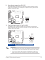
2.6.2 Internal connectors
CAUTION! Do not forget to connect the fan cable to the fan header. Insufcient
air flow inside the system may damage the motherboard components. This is
not a jumper! Do not place a jumper cap on the fan header!
1. Chassis Fan header (4-pin CHA_FAN)
Connect the fan cable to the fan header on the motherboard, ensuring that
the black wire of each cable matches the ground pin of the header.
CHA_FAN
FAN_PWM
FAN_IN
12V
GND
PIN 1
Connector type
WAFER HD 4p, 2.54mm pitch, S/T
2. USB 3.2 Gen 1 header (20-1 pin U32G1_34)
Connect a USB 3.2 Gen 1 module to this header for additional USB 3.2
Gen 1 front or rear panel ports. This header complies with USB 3.2 Gen
1 specications and provides faster data transfer speeds of up to 5 Gbps,
faster charging time for USB-chargeable devices, optimized power efciency,
and backward compatibility with USB 2.0.
+5V_USB_P34
S_U3RXDP3
S_U3TXDN3
GND
S_U2DP3
S_U2DP4
GND
S_U3TXDN4
S_U3RXDP4
+5V_USB_P34
PIN 1 PIN 19
PIN 18
S_U3RXDN3
GND
S_U3TXDP3
S_U2DN3
GND
S_U2DN4
S_U3TXDP4
GND
S_U3RXDN4
U32G1_34
Connector type
BOX HD 2x10p, K20, 2.0mm pitch
La pagina si sta caricando...
La pagina si sta caricando...
La pagina si sta caricando...
La pagina si sta caricando...
La pagina si sta caricando...
La pagina si sta caricando...
La pagina si sta caricando...
La pagina si sta caricando...
La pagina si sta caricando...
La pagina si sta caricando...
La pagina si sta caricando...
La pagina si sta caricando...
La pagina si sta caricando...
La pagina si sta caricando...
La pagina si sta caricando...
La pagina si sta caricando...
La pagina si sta caricando...
La pagina si sta caricando...
La pagina si sta caricando...
La pagina si sta caricando...
La pagina si sta caricando...
La pagina si sta caricando...
La pagina si sta caricando...
La pagina si sta caricando...
La pagina si sta caricando...
La pagina si sta caricando...
La pagina si sta caricando...
La pagina si sta caricando...
La pagina si sta caricando...
La pagina si sta caricando...
La pagina si sta caricando...
La pagina si sta caricando...
La pagina si sta caricando...
La pagina si sta caricando...
La pagina si sta caricando...
-
 1
1
-
 2
2
-
 3
3
-
 4
4
-
 5
5
-
 6
6
-
 7
7
-
 8
8
-
 9
9
-
 10
10
-
 11
11
-
 12
12
-
 13
13
-
 14
14
-
 15
15
-
 16
16
-
 17
17
-
 18
18
-
 19
19
-
 20
20
-
 21
21
-
 22
22
-
 23
23
-
 24
24
-
 25
25
-
 26
26
-
 27
27
-
 28
28
-
 29
29
-
 30
30
-
 31
31
-
 32
32
-
 33
33
-
 34
34
-
 35
35
-
 36
36
-
 37
37
-
 38
38
-
 39
39
-
 40
40
-
 41
41
-
 42
42
-
 43
43
-
 44
44
-
 45
45
-
 46
46
-
 47
47
-
 48
48
-
 49
49
-
 50
50
-
 51
51
-
 52
52
-
 53
53
-
 54
54
-
 55
55


Asus N100I-EM-A Manuale utente
- Categoria
- Schede madri
- Tipo
- Manuale utente
in altre lingue
- English: Asus N100I-EM-A User manual
Documenti correlati
-
Asus Q670EI-IM-A Manuale utente
-
-
-
-
-
-
-
-
-