
MANUALE D’INSTALL A Z I O N E
INST A L L A TION MANUAL
QK-SELSW
SELETTORE - SELECTOR
it - DESCRIZIONE
Il Selettore è progettato per essere collegato con automatismi QUIKO
it- INSTALLAZIONE DA ESTERNO
Il Selettore viene abitualmente fissato nelle vicinanze
dell’ingresso automatico, nei locali interni.
Esso può essere posizionato sia in posizione orizzontale che verti-
cale e può essere applicato a muro o incassato in una scatola
elettrica standard a 3 moduli (ad esempio BTicino Art.503E).
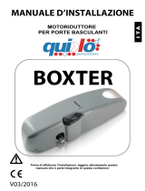
it- INSTALLAZIONE SELETTORE (fig.1)
• Smontare la cornice (Part.A Fig.1) fissata a pressione
• Estrarre la tastiera completa di scheda elettronica svitando le 4 viti
(Part.B Fig.1).
• Forare la base (Part.E Fig.1) per permettere il passaggio dei cavi.
• Fissare la base (Part.E Fig.1) con viti opportune (Part.D Fig.1) al
supporto su cui verrà posizionata, utilizzando le apposite asole.
• Effettuare il cablaggio.
• Rimontare l’apparecchio
en - DESCRIPTION
The Selector has been designed to be connected with QUIKO
automatisms.
en- WALL MOUNTED INSTALLATION
Selector is usually fixed to a suitable support near the automatic entrance,
application indoors. It can be installed in vertical or horizontal position, wall
wall mounted or built-in application using a standard electric box
(i.e. BTicino-art.503E).
en- SELECTOR INSTALLATION (fig.1)
• Remove the plastic frame (Part.A Fig.1).
• Exctract the electric board fixed with the 4 screws (Part.B Fig.1).
• Bore the base (Part.E Fig.1) to admit the cable wire entrance.
• Fix the base (Part.E Fig.1) with screws (Part.D Fig.1) using the
loops to fasten the selector in the correct position.
• Make the cable connections.
•Reassemble the instrument.
fig.1
fig.2
QUIKO ITALY
Via
. Seccalegno 19, 36040 Sossano (VI) Italy
Tel: +39 0444 785513 • Fax: +39 0444 782371
www.quikoitaly.com • E-mail: [email protected]
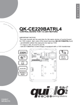
it- INSTALLAZIONE DA INCASSO
• Procedere allo smontaggio come indicato precedentemente
• Solo per la versione standard, forare la base (Part.E Fig.2) per
permettere il passaggio dei cavi.
• Fissare la base (Part.E Fig.2) con viti opportune (Part.D Fig.2) alla
scatola da incasso (Part.H Fig.2) come indicato in figura 2.
• Effettuare il cablaggio come da paragrafo seguente.
• Rimontare l’apparecchio
en- BUILT -IN INSTALLATION
• Dismount the selector as shown before
• For the standard version cut the base(Part.E Fig.2) for the cable
wires passage.
• Fix the base (Part.E Fig.2) with screws (Part.D Fig.2)to the built-in
electric box. (Part.H Fig.2) as shown in the picture 2.
• Make the cable connections.
• Reassemble the instrument.
Vi ringraziamo per la preferenza accordata a questo prodotto. Al fine di ottenere le migliori
prestazioni dal prodotto acquistato, QUIKO raccomanda di leggere e seguire attentamente
le istruzioni di installazione ed uso presenti in questo manuale. L’installazione dev’essere ese-
guita solo da persone professionalmentecompetenti alle quali è rivolto il presente manuale.
Eventuali errori in fase di installazione possono essere fonte di pericolo per persone o cose.
I materiali di imballo (legno, plastica, cartone, ecc.) non vanno dispersi nell’ambiente o lasciati
alla portata dibambini in quanto potenziale fonte di pericolo. Ogni singola fase dell’installa-
zione deve essere effettuata in conformità delle norme vigenti e comunque secondo i dettami
della Buona Tecnica. Assicurarsi, prima di iniziarel’installazione, che il prodotto sia integro e
non abbia subito danni derivanti da trasporti o cattivo immagazzinaggio. Non installare asso-
lutamente il prodotto in ambienti con presenza di gas, vapori o fumi infiammabili. Riportare su
ogni installazione i dati identificativi della porta motorizzata. Verificare che l’impianto elettrico
a monte sia dimensionato correttamente ed abbia tutte le protezioni opportune (interruttore dif-
ferenziale e protezione da sovracorrenti). Negli interventi di manutenzione o riparazione usare
solo ricambi originali. Non manomettere o alterare per nessun motivo gli apparati interni del
dispositivo e tutte le sicurezze previste nella centralina di controllo. Il costruttore declina ogni
responsabilità qualora vengano alterate o manomesse parti interne dell’automatismo o usati
dispositivi di sicurezza nell’impianto diversi da quelli indicati dal costruttore stesso. L’installa-
tore dell’automatismo è tenuto a fornire al responsabile dell’ingresso automatico il manuale
d’uso e tutte le informazioni necessarie per un utilizzo corretto in funzionamento automatico,
manuale (anche nel caso di elettroserratura) ed in casi di emergenza. Questo dispositivo è
stato ideato esclusivamente per il controllo di automatismi per porte scorrevoli di produzione
QUIKO. Ogni altro impiego sarà considerato contrario all’utilizzo previsto dal fabbricante
che, pertanto, non potrà risultare responsabile.
Direttiva macchine - L’istallatore che motorizza una porta diventa ai sensi della direttiva
2006/42/CE il costruttore della macchina porta automatica e deve:
•Predisporre il Fascicolo Tecnico con i documenti indicati nell’allegato V della Direttiva Mac-
chine e conservarlo per almeno 10 anni.
•Redigere la dichiarazione CE di conformità secondo l’allegato II-A della direttiva macchine e
consegnarne una copia all’utilizzatore.
•Apporre la marcatura CE sulla porta motorizzata aisensi del punto 1.7.3 dell’allegato I della
direttiva macchine.
Direttiva di conformità per macchine (Direttiva 2006/42/CE)
Fabbricante:QUIKO ITALY
Indirizzo:Via Seccalegno 19, 36040 Sossano (VI)
Dichiara che il prodotto SELETTORE
•è costruito per essere incorporato in una macchinao per essere assemblato con altri mac-
chinari per costruire una macchina considerata dalla Direttiva 2006/42/CE, come modificata;
•non è dunque conforme in tutti i punti alle disposizioni di questa Direttiva in quanto non an-
cora assemblato con gli altri componenti.
•è conforme alle condizioni delle seguenti altre Direttive CE:
- 2004/108/CE Compatibilità Elettromagnetica e successive modifiche
- 2006/95/CE Bassa Tensione e successive modifiche
e inoltre dichiara che non è consentito mettere in servizio il macchinario fino a che la macchina
in cuisarà incorporata o di cui diverrà componente sia stata identificata e ne sia stata dichia-
rata la conformità alle condizioni della Direttiva 2006/42/CE ed alla legislazione nazionale che
la traspone.
We would like to thank you for choosing this product. In order to optimize the assembly and
installation this product, QUIKO recommends that you read and carefully fol-
low the installation and use instructions provided in this manual. The installation must be per-
formed only by professionally qualified personnel for whom this manual has been written. Any
errors during the installation phase may be the source of danger for people or things. The pac-
kaging materials (wood, plastic, cardboard, etc.) should not be discarded in the environment
or left within reach of children since they are potential sources of danger. Every individual in-
stallation phase must be performed in conformity with current regulations and according to
Good Practice principles. Ensure, before beginning the installation, that the product is complete
and has not been damaged during transport or as a result of improper storage.The product ab-
solutely must not be installed in environments with inflammable gases, vapors or fumes. Re-
cord on each installation the identification data of the motorized door. Verify that the electrical
system upstream is correctly
dimensioned and has all the suitable protections (differential switch and overload protec-
tion).When performing maintenance or repair, use only the original spare parts. Do not tam-
per with or alter for any reason the internal equipment of the device and all the
safeties provided in the control unit. The manufacturer accepts no responsibility in the event
that the internal parts of the automatism are altered or tampered with or if safety devices are
used in the system other than those indicated by the manufacturer.The installer of the auto-
matism must provide the manager of the automated entrance with the use manual and all the
information necessary for the correct use in automatic operation, manual operation (also in the
case of electric locking) and in emergencies.This device has
been exclusively designed for the control of automatisms for sliding doors produced by
QUIKO. Any other use will be considered contrary to the use provided for by the manufacturer
that, therefore, cannot be held responsible.
Machines directive - According to directive 2006/42/EC, the installer that motorizes a door be-
comes the builder of the automatic door machine and must:
•Prepare the Technical File with the documents indicated in Annex V of the Machines Direc-
tive and conserve it forat least 10 years.
•Write up the EC declaration of conformity according to Annex II-A of the Machines Directive
and deliver a copy to the user.
•Affix the EC mark on the motorize door according to point 1.7.3 of AnnexI of the Machines Di-
rective.
Directive of conformity for machines (Direttiva 2006/42/EC)
Fabbricante:QUIKO ITALY
Indirizzo:Via Seccalegno 19, 36040 Sossano (VI)
Declares that the product SELECTOR
•has been built to be incorporated in a machine or to be assembled together with other ma-
chinery in order to con-struct a machine considered by the Directive 98/37 EC, as modified;
•thus it does not satisfy all points of the dispositions of this Directive as it is not yet assembled
with the other compo-nents.
•satisfies the conditions of the following other EC Directives:
- 89/336/CEE Electro-magnetic compatibility and further modifications
- 2006/95 CE LowVoltage and further modifications
and also declares that the machinery can not beused until the machine it is incorporated in or
is a component of has been identified and its conformity to Directive 98/37 CE conditions and
national legislation declared.
Sossano, 06/09/2009
it- BLOCCO TASTIERA
Il selettore può essere bloccato e sbloccato tramite inserimento
di una password. In fase di blocco tutti i tasti sono inibiti ed i led indi-
canti la logica lampeggiano per indicare la condizione di blocco.
Per attivare il blocco procedere come segue:
1. schiacciare PR per più di 5 secondi
2. i led 1, 2, 3, 4, 5 si accendono in sequenza
3. digitare un codice qualsiasi di 4 cifre, avendo cura di annotarlo
4. la tastiera è bloccata, i led indicanti la logica attiva lampeggiano
Per sbloccare la tastiera procedere come segue:
1. digitare il codice utilizzato per bloccare la tastiera.
2. a tastiera sbloccata, i led indicanti la logica attiva smettono di lampeggiare.
In caso di smarrimento del codice di sblocco, usare il codice master: 4231.
en- KEYBOARD BLOCK
The Selector can be blocked and unblocked with a password. If
the keyboard is blocked all buttons are unusable and the selected
logic led blinks to indicate the block modality.
To activate the keyboard blocking:
1. Push PR button for more than 5 seconds
2. Led1, 2, 3, 4, 5 light up in sequence
3. insert a code with 4 numbers, paying attention to record it.
4. The keyboard is blocked and the active logic led blinks.
To unblock the keyboard:
1. Insert the code used to block the keyboard.
2. The keyboard is active and the selected logic led stop blinking.
If you lose your unblock code it is possible to use the master code: 4231
ATTENZIONE
In caso di inattività, dopo 5 secondi dall’ultima operazione ef-
fettuata il selettore esce automaticamente dalla modalità di
programmazione senza salvare i nuovi valori.
ATTENZIONE
In case of inactivity, after 5 seconds from the last operation the
selector exit from the program modality without saving the pa-
rameters.

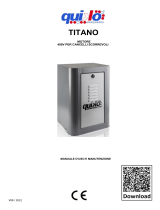
1- apertura manuale - manual opening
2- stop chiuso - stop close
3- stop aperto - stop open
4- 1 radar
5- 2 radar
en- PROGRAM SETTING
1 - Press the PR and ESC button for over 3 seconds
2- Every Led lighting, the selector is in the PROGRAM MODE.
To exit from the Program Mode without save the settings press ESC,
press PR to exit saving the new settings.
3- Select the parameter will be modified pushing the correspondent
button.
4- The yelow Leds show the selected parameter
For every parameter it is possible to choose 5 setting levels, selecting
the correspondent button. Modify the different levels selecting the va-
lues as shown in the 2 and 3 tables
6 – Use the PR button to confinrm and save th new setting or the ESC
button to exit without save the settings changed.
Now it is possible to select and change the other parameter.
7 – To memorize and activate the new parameters exit from the pro-
gram mode pushing the PR button.To exit without saving press ESC.
(see point 2)
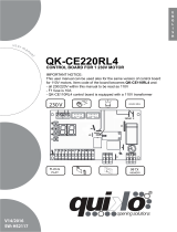
it- CONNESSIONI ELETTRICHE
Per il collegamento utilizzare un cavo schermato a 4 fili 0,22mm
(max.50m): connettere i 4 conduttori interni del cavo schermato rispet-
tando le corrispondenze indicate dalle serigrafie poste sia sulla morset-
tiera della centrale elettronica che su quella del selettore multilogica
(Fig.4). Non collegare lo schermo del cavo utilizzato.
Il contatto LOCK1 e LOCK2 deve essere chiuso tramite connettore o
cavo.
en- ELECTRIC CONNECTION
For the connection, use a screened cable with 4 wires of 0.22 mm
(max.50m): connect the 4 inner conductors of the screened cable re-
specting the matches indicated by the silk-screen printing located both
on the terminal box of the electronic board and on that of the multilogic
selector. Do not connect the screen of the used cable.
LOCK1 and LOCK2 contact must be closed by jumper or wire.
fig.4
it- SELEZIONE LOGICHE
• Stop Chiuso: l’automatismo comanda la completa chiusura delle ante.
In questa logica gli ingressi START1 e START2
della scheda elettronica di controllo non sono monitorati; se presente,
l’elettroserratura blocca le ante. Il tasto di comando di apertura è disat-
tivo.
• Stop Aperto: l’automatismo comanda la completa apertura delle ante.
In questa logica gli ingressi START1 e START2
della scheda elettronica di controllo non sono monitorati.
• 2 Radar (Entrata ed Uscita) : entrambi gli ingressi START1 e START2
della scheda elettronica di controllo sono monitorati.
Un segnale proveniente da un sensore collegato ad uno di questi in-
gressi provoca l’apertura e conseguente chiusura
delle ante. L’elettroserratura, se presente, non blocca mai le ante.
•1 Radar (Solo Uscita): solo l’ingresso START 2 della scheda elettro-
nica di controllo è monitorato. Un segnale proveniente
da un sensore collegato a questo ingresso provoca l’apertura e conse-
guente chiusura delle ante. L’elettroserratura, se presente,
blocca le ante tutte le volte che queste raggiungono la posizione di com-
pleta chiusura.
• Apertura Manuale: l’automatismo comanda la completa chiusura delle
ante. In questa logica gli ingressi START1 e
START2 della scheda elettronica di controllo non sono monitorati e, se
presente, l’elettroserratura blocca le ante.
L’automatismo effettua una manovra di apertura e chiusura solo ed
esclusivamente nei seguenti casi:
- pressione del tasto di comando di apertura manuale
- a seguito di un tentativo di apertura dell’anta in caso di assenza di elet-
troserratura e con la funzione “push&go” attiva.
I led di segnalazione indicano la logica attualmente attiva (led acceso).
Per cambiare la logica premere il tasto corrispondente alla logica che si
vuole selezionare; ad ogni pressione di un tasto il led corrispondente
lampeggia per alcuni secondi;nel momento in cui la luce diventa fissa la
scheda di controllo acquisisce la nuova logica.
Il Led Segnalazione Batteria si accende per segnalare l’assenza di ali-
mentazione di rete ed il conseguente funzionamento
a batteria dell’automatismo. Inoltre il lampeggio di tale led segnala basso
livello di carica delle batterie.
ATTENZIONE!
In caso di selezione della condizione di apertura parziale con
la logica di Stop aperto già attiva, sarà necessario far effettuare all’au-
tomatismo una manovra completa per rendere attive le impostazioni di
apertura parziale.
In caso di reset l’apertura parziale viene disattivata.
en - OPERATING LOGICS
• Stop Close: the automatism controls the complete closure of the door
wings. In this logic the inputs START1 and START2 of the electronic con-
trol card are not monitored; if present, the electric locking system blocks
the door wings.
• Stop Open: the automatism controls the complete opening of the door
wings.In this logic the inputs START1 and START2 of the electronic con-
trol card are not monitored.
• 2 radar (Entry-exit radar): both the inputs START 1 and START 2 of
the electronic controlcard are monitored. A signal originating from a sen-
sor connected to one of theseinputs triggers the opening and conse-
quent closing of the door wings.The electriclocking system, if present,
never blocks the door wings.
• 1 radar (Exit-only radar): only the input START 2 of the electronic con-
trol card is moni-tored.A signal originating from a sensor connected to
this input triggers the open-ing and consequent closing of the door
wings.The electric locking system, if present, blocks the door wings
every time that these reach the position of complete closure.
• Manual opening: the automatism controls the complete closure of the
door wings. In this logic the inputs START1 and START2 of the electro-
nic control card are not monitored and the electric locking system, if pres-
ent, blocks the door wings
The automatism controls a complete opening and complete closure of
the doors when:
- you push the manual opening button
- you try to open the door with the “push&go” function active and wi-
thout the electric locking system.
The led indicators indicate the logic currently active (led lit up).To change
the logic press the SELECT key; every time the key
is pressed the led corresponding to the various logics lights up in se-
quence. When the desired logic is reached, the led blinks
for a few seconds; when the light remains on, the control card acquires
the new logic.
The battery led is on if the electrical power is out, the automatism runs
with battery power.
The led blink to show a low charge battery level.
ATTENTION!
If you select the partial opening mode with the Stop Open
logic already set, to activate the partial opening settings it would be
necessary that the automatism runs a complete cycle. In case of
“reset” , the partial opening will be deactivated.
it- PROGRAMMAZIONE
1 - Premere il tasto PR e il tasto ESC per più di 3 secondi.
2- Tutti i led si mettono a lampeggiare, indicando l’ingresso in MODA-
LITÀ PROGRAMMAZIONE. Dalla modalità programmazione premere
ESC per uscire senza salvare o PR per uscire salvando le modifiche
apportate.
3- Selezionare il parametro da modificare cliccando il tasto corrispon-
dente.
4- I led gialli indicano il valore attuale del parametro selezionato.
Per ogni parametro è possibile scegliere 5 livelli di regolazione pre-
mendo il tasto corrispondente al livello desiderato. Ad ogni livello corri-
sponde un valore come indicato da Tab.2 e Tab.3.
6 – Premere il tasto PR per memorizzare il valore e ritornare alla mo-
dalità di scelta parametro o il tasto ESC per uscire senza salvare il
nuovo valore. E’ ora possibile selezionare altri parametri da modifi-
care.
7 – Per memorizzare e rendere attivi i nuovi valori è necessario uscire
dalla modalità programmazione tramite il tasto PR. Per uscire senza
salvare nessuna modifica premere ESC (vedi punto 2).
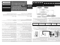
1 2 3 4 5
Velocità Apertura
Opening Speed
Velocità Chiusura
Closing Speed
Tempo di sosta
Idle time
Antischiacciamento apertura
Opening anticrushing
Antischiacciamenti chiusura
Closing Anticrushing
N Descrizione / Description Livelli / levels
1 2 3 4 5
1 Velocità Apertura / Opening speed 20°/s 30°/s 40°/s 50°/s 60°/s
2 Velocità Chiusura / Closing speed 10°/s 20°/s 30°/s 35°/s 40°/s
3 Tempo di sosta / Idle time 0s 1s 3s 5s 10s
4Antischiacciamento apertura / Opening anticrushing 13579
5Antischiacciamenti chiusura / Closing Anticrushing 13579
TAB.2 - QK-SW200
Livelli / levels
1 2 3 4 5
20°/s 30°/s 40°/s 50°/s -
10°/s 20°/s 30°/s 35°/s 40°/s
0s 1s 3s 5s 10s
1 3 5 7 9
1 3 5 7 9
TAB.3 - QK-SW80
- comando apertura manuale
- manual opening device
- funzionamento a batteria led
- battery mode led
- reset
PR -Programmazione
-Program mode
ESC -Uscita
-Exit
LOGICHE - USER MODE
PROGRAMMAZIONE
PROGRAM MODE
-
 1
1
-
 2
2


in altre lingue
- English: quiko QK-SELSW User manual
Documenti correlati
-
 quiko ICARUS Manuale utente
-
 quiko ICARUS Manuale utente
-
 quiko QK-CE220BASC Manuale utente
-
 quiko SCARABEO Manuale utente
-
 quiko BOXTER+CE220BASC Manuale utente
-
 quiko QK-CE220BATRL4 Manuale utente
-
 quiko QK-CE220RLINV Manuale utente
-
 quiko QK-CE220RL4 Manuale utente
-
 quiko TITANO+QK-CE220RLX(V05) Manuale utente
-
 quiko SCARABEO Manuale utente


