HK Audio Digital Field Controller (DFC) Manuale utente
- Categoria
- Apparecchiature musicali supplementari
- Tipo
- Manuale utente

Manual 2.1
Digital Field
Controller
English
Deutsch
DFC_Manual_2.1 21.04.2004 11:12 Uhr Seite 1 (Schwarz Bogen)

Wichtige Sicherheitshinweise!
Bitte vor Gebrauch lesen und für späteren Gebrauch
aufbewahren!
• Read all of these instructions!
• Read all of these instructions!
• Save these instructions for later use!
•Follow all warnings and instructions marked on the product!
• Do not use this product near water, i.e. bathtub, sink, swimming pool,
wet basement, etc.
• Do not place this product on an unstable cart, stand or table. The
product may fall, causing serious damage to the product or to persons!
• Slots and openings in the cabinet and the back or bottom are provided
for ventilation; to ensure reliable operation of the product and to
protect it from overheating, these openings must not be blocked or
covered. This product should not be placed in a built-in installation
unless proper ventilation is provided.
• This product should not be placed near a source of heat such as a
stove, radiator, or another heat producing amplifier.
• Use only the supplied power supply or power cord. If you are not sure
of the type of power available, consult your dealer or local power
company.
• Do not allow anything to rest on the power cord. Do not locate this
product where persons will walk on the cord.
• Never break off the ground pin on the power supply cord.
• Power supply cords should always be handled carefully. Periodically
check cords for cuts or sign of stress, especially at the plug and the
point where the cord exits the unit.
• The power supply cord should be unplugged when the unit is to be
unused for long periods of time.
• If this product is to be mounted in an equipment rack, rear support
should be provided.
• This product should be used only with a cart or stand that is recom-
mended by HK AUDIO
®
.
• Never push objects of any kind into this product through cabinet slots
as they may touch dangerous voltage points or short out parts that
could result in risk of fire or electric shock. Never spill liquid of any
kind on the product.
• Do not attempt to service this product yourself, as opening or
removing covers may expose you to dangerous voltage points or other
risks. Refer all servicing to qualified service personnel.
• Clean only with dry cloth.
• Do not defeat the safety purpose of the polarized or grounding-type
plug. A polarized plug has two blades with one wider than the other. A
grounding type plug has two blades and a third grounding prong. The
wide blade or the third prong are provided for the safety. If the
provided plug does not fit into your outlet, consult an electrician for
replacement of the obsolete outlet.
• Unplug this product from the wall outlet and refer servicing to
qualified service personnel under the following conditions:
• When the power cord or plug is damaged or frayed.
• If liquid has been spilled into the product.
• If the product has been exposed to rain or water.
• If the product does not operate normally when the operating
instructions are followed.
• If the product has been dropped or the cabinet has been damaged.
• If the product exhibits a distinct change in performance, indicating a
need of service!
• Adjust only these controls that are covered by the operating
instructions since improper adjustment of other controls may result in
damage and will often require extensive work by a qualified technician
to restore the product to normal operation.
• Exposure to extremely high noise levels may cause a permanent
hearing loss.
• Individuals vary considerably in susceptibility to noise induced hearig
loss, but nearly everyone will lose some hearing if exposed to
sufficiently intense noise for a sufficient time. The U.S. Government´s
Occupational Safety and Health Administration (OSHA) has specified
the following permissible noise level exposures:
Duration Per Day In Hours Sound LeveldBA, Slow Response
890
692
495
397
2 100
11/2 102
1 105
1/2 110
1/4 or less 115
• According to OSHA, any exposure in excess of the above permissible
limits could result in some hearing loss.
• Ear plug protectors in the ear canals or over the ears must be worn
when operating this amplification system in order to prevent a
permanent hearing loss if exposure is in excess of the limits as set
forth above. To ensure against potentially dangerous exposure to high
sound pressure levels, it is recommended that all persons exposed to
equipment capable of producing high sound pressure levels such as
this amplification system be protected by hearing protectors while this
unit is in operation.
•Fuses: Replace with IEC 127 (5x 20 mms) type and rated fuse for best
performance only.
TO PREVENT THE RISK OF FIRE AND SHOCK HAZARD, DO NOT
EXPOSE THIS APPLIANCE TO MOISTURE OR RAIN. DO NOT OPEN
CASE; NO USER SERVICE-ABLE PARTS INSIDE.
REFER SERVICING TO QUALIFIED SERVICE PERSONNEL.
• The unit has been built by HK AUDIO
®
in accordance with IEC 60065
and left the factory in safe working order. To maintain this condition
and ensure non-risk operation, the user must follow the advice and
warning comments found in the operating instructions. The unit
conforms to Protection Class 1 (protectively earthed).
• HK AUDIO
®
ONLY GUARANTEE THE SAFETY, RELIABILITY AND
EFFICIENCY OF THE UNIT IF:
• Assembly, extension, re-adjustment, modifications or repairs are
carried out by HK AUDIO
®
or by persons authorized to do so.
• The electrical installation of the relevant area complies with the
requirements of IEC (ANSI) specifications.
• The unit is used in accordance with the operating instructions.
• The unit is regularly checked and tested for electrical safety by a
competent technician.
WARNING:
• If covers are opened or sections of casing are removed, except where
this can be done manually, live parts can become exposed.
• If it is necessary to open the unit this must be insulated from all power
sources. Please take this into account before carrying out adjustments,
maintenance, repairs and before replacing parts.
• The appliance can only be insulated from all power sources if the
mains connection is unplugged.
• Adjustment, maintenance and repairs carried out when the unit has
been opened and is still live may only be performed by specialist
personnel who are authorized by the manufacturer (in accordance with
VBG 4) and who are aware of the associated hazards.
• Loudspeaker outputs which have the IEC 417/5036 symbol (Diagram 1,
below) can carry voltages which are hazardous if they are made contact
with. Before the unit is switched on, the loudspeaker should therefore
only be connected using the lead recommended by the manufacturer.
• Where possible, all plugs on connection cables must be screwed or
locked onto the casing.
• Replace fuses only with IEC127 type and specified ratings.
• It is not permitted to use repaired fuses or to short-circuit the fuse
holder.
• Never interrupt the protective conductor connection.
• Surfaces which are equipped with the "HOT" mark (Diagram 2, below),
rear panels or covers with cooling slits, cooling bodies and their
covers, as well as tubes and their covers are purposely designed to
dissipate high temperatures and should therefore not be touched.
• High loudspeaker levels can cause permanent hearing damage. You
should therefore avoid the direct vicinity of loudspeakers operating at
high levels.
Wear hearing protection if continuously exposed to high levels.
MAINS CONNECTION:
• The unit is designed for continuous operation.
• The set operating voltage must match the local mains supply voltage.
• The unit is connected to the mains via the supplied power unit or
power cable.
• Power unit: Never use a damaged connection lead. Any damage must
be rectified by a competent technician.
•Avoid connection to the mains supply in distributor boxes together
with several other power consumers.
• The plug socket for the power supply must be positioned near the unit
and must be easily accessible.
PLACE OF INSTALLATION:
• The unit should stand only on a clean, horizontal working surface.
• The unit must not be exposed to vibrations during operation.
• Keep away from moisture and dust where possible.
• Do not place the unit near water, baths, wash basins, kitchen sinks,
wet areas, swimming pools or damp rooms. Do not place objects
containing liquid on the unit - vases, glasses, bottles etc.
• Ensure that the unit is well ventilated.
• Any ventilation openings must never be blocked or covered. The unit
must be positioned at least 20 cm away from walls. The unit may only
be fitted in a rack if adequate ventilation is ensured and if the manu-
facturer's installation instructions are followed.
• Keep away from direct sunlight and the immediate vicinity of heating
elements and radiant heaters or similar devices.
• If the unit is suddenly moved from a cold to a warm location,
condensation can form inside it. This must be taken into account
particularly in the case of tube units. Before switching on, wait until
the unit has reached room temperature.
• Accessories: Do not place the unit on an unsteady trolley, stand,
tripod, base or table. If the unit falls down, it can cause personal injury
and itself become damaged. Use the unit only with the trolley, rack
stand, tripod or base recommended by the manufacturer or purchased
together with the unit. When setting the unit up, all the manufacturer's
instructions must be followed and the setup accessories recommended
by the manufacturer must be used. Any combination of unit and stand
must be moved carefully. A sudden stop, excessive use of force and
uneven floors can cause the combination of unit and stand to tip over.
• Additional equipment: Never use additional equipment which has not
been recommended by the manufacturer as this can cause accidents.
•To protect the unit during bad weather or when left unattended for
prolonged periods, the mains plug should be disconnected. This
prevents the unit being damaged by lightning and power surges in the
AC mains supply.
Diagram 1 Diagram 2
• Das Gerät wurde von HK AUDIO
®
gemäß IEC 60065 gebaut und hat das
Werk in sicherheitstechnisch einwandfreiem Zustand verlassen. Um
diesen Zustand zu erhalten und einen gefahrlosen Betrieb sicherzustellen,
muss der Anwender die Hinweise und die Warnvermerke beachten, die in
der Bedienungsanleitung enthalten sind. Das Gerät entspricht der Schutz-
klasse I (schutzgeerdet).
• DIE SICHERHEIT, ZUVERLÄSSIGKEIT UND LEISTUNG DES GERÄTES
WIRD VON HK AUDIO
®
NUR DANN GEWÄHRLEISTET, WENN:
• Montage, Erweiterung, Neueinstellung, Änderungen oder Reparaturen von
HK AUDIO
®
oder von dazu ermächtigten Personen ausgeführt werden.
• die elektrische Installation des betreffenden Raumes den Anforderungen
von IEC (ANSI)-Festlegungen entspricht.
• das Gerät in Übereinstimmung mit der Gebrauchsanweisung verwendet
wird.
WARNUNG:
•Wenn Abdeckungen geöffnet oder Gehäuseteile entfernt werden, außer
wenn dies von Hand möglich ist, können Teile freigelegt werden, die
Spannung führen.
•Wenn ein Öffnen des Gerätes erforderlich ist, muss das Gerät von allen
Spannungsquellen getrennt sein. Berücksichtigen Sie dies vor dem
Abgleich, vor einer Wartung, vor einer Instandsetzung und vor einem Aus-
tausch von Teilen.
• Ein Abgleich, eine Wartung oder eine Reparatur am geöffneten Gerät unter
Spannung darf nur durch eine vom Hersteller autorisierte Fachkraft (nach
VBG 4) geschehen, die mit den verbundenen Gefahren vertraut ist.
• Lautsprecher-Ausgänge, die mit dem IEC 417/5036-Zeichen (Abb.1,
s.unten) versehen sind können berührungsgefährliche Spannungen
führen. Deshalb vor dem Einschalten des Gerätes Verbindung nur mit
dem vom Hersteller empfohlenen Anschlusskabel zum Lautsprecher
herstellen.
• Alle Stecker an Verbindungskabeln müssen mit dem Gehäuse verschraubt
oder verriegelt sein, sofern möglich.
• Es dürfen nur Sicherungen vom angegebenen Typ und der angegebenen
Nennstromstärke als Ersatz verwendet werden.
• Eine Verwendung von geflickten Sicherungen oder Kurzschließen des Hal-
ters ist unzulässig.
• Niemals die Schutzleiterverbindung unterbrechen.
• Oberflächen, die mit dem "HOT"-Zeichen (Abb.2, s.unten) versehen sind,
Rückwände oder Abdeckungen mit Kühlschlitzen, Kühlkörper und deren
Abdeckungen, sowie Röhren und deren Abdeckungen können im Betrieb
erhöhte Temperaturen annehmen und sollten deshalb nicht berührt wer-
den.
• Hohe Lautstärkepegel können dauernde Gehörschäden verursachen.
Vermeiden Sie deshalb die direkte Nähe von Lautsprechern, die mit hohen
Pegeln betrieben werden. Verwenden Sie einen Gehörschutz bei dauernder
Einwirkung hoher Pegel.
NETZANSCHLUSS:
• Das Gerät ist für Dauerbetrieb ausgelegt.
• Die eingestellte Betriebsspannung muss mit der örtlichen Netzspannung
übereinstimmen.
• Der Anschluss an das Stromnetz erfolgt mit dem mitgelieferten Netzteil
oder Netzkabel.
• Netzteil: Eine beschädigte Anschlussleitung kann nicht ersetzt werden.
Das Netzteil darf nicht mehr betrieben werden.
•Vermeiden Sie einen Anschluss an das Stromnetz in Verteilerdosen
zusammen mit vielen anderen Stromverbrauchern.
• Die Steckdose für die Stromversorgung muss nahe am Gerät angebracht
und leicht zugänglich sein.
AUFSTELLUNGSORT:
• Das Gerät sollte nur auf einer sauberen, waagerechten Arbeitsfläche stehen.
• Das Gerät darf während des Betriebs keinen Erschütterungen ausgesetzt
sein.
•Feuchtigkeit und Staub sind nach Möglichkeit fernzuhalten.
• Das Gerät darf nicht in der Nähe von Wasser, Badewanne, Waschbecken,
Küchenspüle, Nassraum, Swimmingpool oder feuchten Räumen betrieben
werden. Keine mit Flüssigkeit gefüllten Gegenstände -Vase, Gläser,
Flaschen etc. auf das Gerät stellen.
• Sorgen Sie für ausreichende Belüftung der Geräte.
•Eventuelle Ventilationsöffnungen dürfen niemals blockiert oder abgedeckt
werden. Das Gerät muß mindestens 20 cm von Wänden entfernt aufge-
stellt werden. Das Gerät darf nur dann in ein Rack eingebaut werden,
wenn für ausreichende Ventilation gesorgt ist und die Einbauanweisungen
des Herstellers eingehalten werden.
•Vermeiden Sie direkte Sonneneinstrahlung sowie die unmittelbare Nähe
von Heizkörpern und Heizstrahlern oder ähnlicher Geräte.
•Wenn das Gerät plötzlich von einem kalten an einen warmen Ort gebracht
wird, kann sich im Geräteinnern Kondensfeuchtigkeit bilden. Dies ist
insbesondere bei Röhrengeräten zu beachten. Vor dem Einschalten
solange warten bis das Gerät Raumtemperatur angenommen hat.
• Zubehör: Das Gerät nicht auf einen instabilen Wagen, Ständer, Dreifuß,
Untersatz oder Tisch stellen. Wenn das Gerät herunterfällt, kann es
Personenschäden verursachen und selbst beschädigt werden.
Verwenden Sie das Gerät nur mit einem vom Hersteller empfohlenen oder
zusammen mit dem Gerät verkauften Wagen, Rack, Ständer, Dreifuß oder
Untersatz. Bei der Aufstellung des Gerätes müssen die Anweisungen des
Herstellers befolgt und muss das vom Hersteller empfohlene Aufstell-
zubehör verwendet werden. Eine Kombination aus Gerät und Gestell muss
vorsichtigt bewegt werden. Plötzliches Anhalten, übermäßige
Kraftanwendung und ungleichmäßige Böden können das Umkippen
der Kombination aus Gerät und Gestell bewirken.
•Zusatzvorrichtungen: Verwenden Sie niemals Zusatzvorrichtungen, die
nicht vom Hersteller empfohlen wurden, weil dadurch Unfälle verursacht
werden können
• Zum Schutz des Gerätes bei Gewitter oder wenn es längere Zeit nicht
beaufsichtigt oder benutzt wird, sollte der Netzstecker gezogen werden.
Dies verhindert Schäden am Gerät aufgrund von Blitzschlag und
Spannungsstößen im Wechselstromnetz.
Abb.1 Abb.2
Important Safety Instructions
Before connecting, read instructions
Important Advice on Safety!
Please read before use and keep for later use!
DFC_Manual_2.1 21.04.2004 11:12 Uhr Seite 2 (Schwarz Bogen)

• L'appareil a été conçu par HK AUDIO
®
selon la norme IEC 60065 et a
quitté l'entreprise dans un état irréprochable. Afin de conserver cet
état et d'assurer un fonctionnement sans danger de l'appareil nous
conseillons à l'utilisateur la lecture des indications de sécurité contenues
dans le mode d'emploi. L'appareil est conforme à la classification I
(mise à terre de protection).
• SURETE, FIABILITE ET EFFICACITE DE L'APPAREIL NE SONT
GARANTIS PAR HK AUDIO
®
QUE SI:
• Montage, extension, nouveau réglage, modification ou réparation
sont effectués par HK AUDIO
®
ou par toute personne autorisée
par HK AUDIO
®
.
• L'installation électrique de la pièce concernée correspond aux normes
IEC (ANSI).
• L'utilisation de l'appareil suit le mode d'emploi.
AVERTISSEMENT:
•A moins que cela ne soit manuellement possible, tout enlèvement
ou ouverture du boîtier peut entrainer la mise au jour de pieces
sous tension.
• Si l'ouverture de l'appareil est nécessaire, celui-ci doit être coupé de
chaque source de courant. Ceci est à prendre en considération avant
tout ajustement, entretien, réparation ou changement de pieces.
• Ajustement, entretien ou réparation sur l'appareil ouvert et sous
tension ne peuvent être éffectués que par un spécialiste autorisé par le
fabricant (selon VBG4). Le spécialiste étant conscient des dangers liés
à ce genre de réparation.
• Les sorties de baffles qui portent le signe IEC 417/5036 (fig. 1, voir
en bas) peuvent être sous tension dangereuse. Avant de brancher
l'appareil utiliser uniquement le câble de raccordement conseillé par
le fabricant pour raccorder les baffles.
•Toutes les prises des câbles de raccordement doivent être, si possible,
vissées ou verrouillées sur le boîtier.
• Utilisez subsidiairement uniquement des fusibles de type et de
puissance de courant nominale donnés.
• L'utilisation de fusibles rafistolés ou court-circuites est inadmissible.
• Ne jamais interrompre la connexion du circuit protecteur.
• Il est conseillé de ne pas toucher aux surfaces pourvues du signe
"HOT" (fig. 2, voir en bas), aux parois arrières ou caches munis de
fentes d'aération, éléments d'aération et leurs caches ansi qu'aux
tubes et leurs caches.
Ces éléments pouvant atteindre des températures élévées pendant
l'utilisation de l'appareil.
• Les Niveaux de puissance élévés peuvent entrainer des lésions auditives
durables. Evitez donc la proximité de haut-parleurs utilisés à haute
puissance. Lors de haute puissance continue utilisez une protection
auditive.
BRANCHEMENT SUR LE SECTEUR:
• L'appareil est conçu pour une utilisation continue.
• La tension de fonctionnement doit concorder avec la tension secteur
locale.
• Le raccordement au réseau éléctrique s'effectue avec l'adaptateur ou le
cordon d´alimentation livré avec l'appareil.
• Adaptateur: Un câble de raccordement abimé ne peut être remplacé.
L'adaptateur est inutilisable.
•Evitez un raccordement au réseau par des boîtes de distribution
surchargées.
• La prise de courant doit être placée à proximité de l'appareil et facile
à atteindre.
LIEU D'INSTALLATION:
• L'appareil doit être placé sur une surface de travail propre et horizontale.
• L'appareil en marche ne doit en aucun cas subir des vibrations.
•Evitez dans la mesure du possible poussière et humidité.
• L'appareil ne doit pas être placé à proximité d'eau, de baignoire,
lavabo, évier, pièce d'eau, piscine ou dans une pièce humide.
Ne placez aucun vase, verre, bouteille ou tout objet rempli de liquide sur
l'appareil.
• L'appareil doit être suffisamment aéré.
• Ne jamais recouvrir les ouvertures d'aération. L'appareil doit être placé
à 20 cm du mur au minimum. L'appareil peut être monté dans un Rack
si une ventilation suffisante est possible et si les conseils de montage
du fabricant sont suivis.
•Evitez les rayons de soleil et la proximité de radiateurs, chauffages etc.
• Une condensation d'eau peut se former dans l'appareil si celui-ci est
transporté brusquement d'un endroit froid à un endroit chaud.
Ceci est particulièrement important pour des appareils à tubes.
Avant de brancher l'appareil attendre qu'il ait la température ambiante.
• Accessoires: L'appareil ne doit être placé sur un chariot, support,
trépied, bâti ou table instable. Une chute de l'appareil peut entrainer
aussi bien des dommages corporels que techniques. Utilisez l'appareil
uniquement avec un chariot, Rack, support, trépied ou bâti conseillé
par le fabricant ou vendu en combinaison avec l'appareil.
Les indications du fabricant pour l'installation de l'appareil sont à
suivre, et les accessoires d'installation conseillés par le fabricant sont
à utiliser. Un ensemble support et appareil doit être déplacé avec
précaution.
Des mouvements brusques et des revêtements de sol irreguliers
peuvent entrainer la chute de l´ensemble.
• Equipements supplémentaires: Ne jamais utiliser un équipement
supplémentaire n'ayant pas été conseillé par le fabricant, ceci pouvant
entrainer des accidents.
• Afin de protéger l'appareil pendant un orage ou s'il ne doit pas être
utilisé pendant un certain temps, il est conseillé d'enlever la prise
au secteur.
Ceci évite des dommages dûs à la foudre ou à des coups de tension
dans le réseau à courant alternatif.
Fig. 1 Fig. 2
• L'apparecchio è stato costruito dalla HK AUDIO
®
secondo la normativa
europea IEC 60065 ed ha lasciato il nostro stabilimento in stato
ineccepibile. Per garantire il mantenimento di tale stato e un utilizzo
assolutamente privo di rischi l'utente è tenuto ad osservare le indicazioni
e gli avvertimenti di sicurezza contenuti nelle istruzioni per l'uso.
L'apparecchio rispecchia il livello di sicurezza I (collegato a terra).
• Sicurezza, affidabilità e prestazioni dell'apparecchio vengono garantiti
dalla HK AUDIO
®
solo ed esclusivamente se:
• Montaggio, ampliamento, rimessa a punto, modifiche e riparazioni
vengono eseguite dalla HK AUDIO
®
stessa o da personale da essa
autorizzato.
• Gli impianti elettrici nei locali prescelti per l'uso dell'apparecchio
rispondono alle normative stabilite dall'ANSI.
• L'apparecchio viene utilizzato come indicato nel libretto delle istruzioni
per l'uso.
Avvertimenti:
• In caso di apertura di parti di rivestimento o rimozione di parti
dell'involucro, a meno che non si tratti di pezzi rimovibili semplicemente
a mano, possono venire alla luce parti dell'apparecchio conduttrici di
tensione.
• Se l'apertura dell'apparecchio dovesse risultare necessaria è indispensabile
staccare precedentemente quest'ultimo da tutte le fonti di tensione.
Rispettare tale misura di prevenzione anche prima di un allineamento, di
operazioni di manutenzione, della messa in esercizio o della sostituzione
di componenti all'interno dell'apparecchio.
• Allineamento, operazioni di manutenzione o eventuali riparazioni dell'ap-
parecchio in presenza di tensione vanno eseguite esclusivamente da per-
sonale specializzato ed autorizzato, in grado di eseguire tali operazioni evi-
tandone i rischi connessi.
• Le uscite degli altoparlanti contrassegnate dai caratteri IEC 417/5036 (vedi
illustrazione 1 a fondo pag.) possono essere conduttrici di tensione peri-
colosa con cui evitare il contatto. Per questo motivo, prima
di accendere l'apparecchio, collegare quest'ultimo agli altoparlanti
servendosi esclusivamente del cavetto d'allacciamento indicato
dal produttore.
•Tutte le spine e i cavi di collegamento devono essere avvitati o fissati
all'involucro dell'apparecchio per quanto possibile.
•Tutti i fusibili di sicurezza vanno sostituiti esclusivamente con fusibili del
tipo prescritto e valore della corrente nominale indicato.
• L'utilizzo di fusibili di sicurezza non integri e la messa in corto circuito
del sostegno di metallo sono proibite.
• Non interrompere mai il collegamento con il circuito di protezione.
• Superfici contrassegnate dalla parola "HOT" (vedi illustrazione 2 a fondo
pag.), cosi come griglie di aerazione, dispositivi di raffreddamento e i loro
rivestimenti di protezione, oppure valvole e i relativi rivestimenti protetti-
vi possono surriscaldarsi notevolmente durante l'uso e per questo motivo
non vanno toccate.
• L'ascolto di suoni ad alto volume può provocare danni permanenti
all'udito. Evitate perciò la diretta vicinanza con altoparlanti ad alta
emissione di suono e utilizzate cuffie protettive in caso ciò non sia
possibile.
Alimentazione:
• L'apparecchio è concepito per il funzionamento continuo.
• La tensione di esercizio deve corrispondere alla tensione di rete a cui ci
si allaccia.
• L'allacciamento alla rete elettrica avviene tramite alimentatore o cavetto
d'alimentazione consegnato insieme all'apparecchio.
• Alimentatore: un cavo di connessione danneggiato non può essere
sostituito. L'alimentatore non può più essere utilizzato.
•Evitate un allacciamento alla rete di corrente utilizzando cassette di
distribuzione sovraccariche.
• La spina di corrente deve essere situata nelle vicinanze dell'apparecchio
e facilmente raggiungibile in qualsiasi momento.
Locali di collocamento:
• Opportuno collocare l'apparecchio su una superficie pulita e orizzontale.
• Non sottoporre l'apparecchio in funzione a scosse e vibrazioni.
• Proteggere l'apparecchio per quanto possibile da umidità e polvere.
• Non collocare l'apparecchio vicino ad acqua, vasche da bagno, lavandini,
lavelli da cucina, locali umidi o piscine. Non appoggiare recipienti conte-
nenti liquidi - vasi, bicchieri, bottiglie, ecc. - sull'apparecchio.
• Provvedere ad una buone aerazione dell'apparecchio.
•Eventuali aperture previste per la ventilazione dell'apparecchio non vanno
ne bloccate, ne mai coperte. L'apparecchio va collocato ad almeno 20 cm
di distanza dalle pareti circostanti e può essere inserito tra altre compo-
nenti di un impianto solo in caso di sufficiente ventilazione e qualora le
direttive di montaggio del produttore vengano rispettate.
•Evitare di esporre l'apparecchio ai raggi del sole e di collocarlo diretta-
mente nelle vicinanze di fonti di calore come caloriferi, stufette, ecc.
• Se l'apparecchio viene trasportato rapidamente da un locale freddo ad
uno riscaldato può succedere che al suo interno si crei della condensa.
Ciò va tenuto in considerazione soprattutto in caso di apparecchi a valvole.
Attendere che l'apparecchio abbia assunto la temperatura ambiente prima
di accenderlo.
• Accessori: non collocare l'apparecchio su carrelli, supporti, treppiedi, su-
perfici o tavoli instabili. Se l'apparecchio dovesse cadere a terra potrebbe
causare danni a terzi o danneggiarsi irreparabilmente. Utilizzate per il col-
locamento dell'apparecchio supporti, treppiedi e superfici che siano con-
sigliate dal produttore o direttamente comprese nell'offerta di vendita. Per
il collocamento dell'apparecchio attenetevi strettamente alle istruzioni del
produttore, utilizzando esclusivamente accessori da esso consigliati. L'ap-
parecchio in combinazione ad un supporto va spostato con molta atten-
zione. Movimenti bruschi o il collocamento su pavimenti non piani posso-
no provocare la caduta dell'apparecchio e del suo supporto.
• Accessori supplementari: non utilizzate mai accessori supplementari che
non siano consigliati dal produttore, potendo essere ciò causa di incidenti.
• Per proteggere l'apparecchio in caso di temporali o nel caso questo non
venisse utilizzato per diverso tempo si consiglia di staccarne la spina di
corrente.
In questo modo si evitano danni all'apparecchio dovuti a colpi di fulmine
o ad improvvisi aumenti di tensione nel circuito di corrente alternata.
Illustrazione 1 Illustrazione 2
• El aparato ha sido producido por HK AUDIO
®
según el IEC 60065 y salió
de la fábrica en un estado técnicamente perfecto. Para conservar este
estado y asegurar un funcionamiento sin peligros el usuario debe tener en
cuenta las indicaciones y advertencias contenidas en las instrucciones de
manejo. l aparato corresponde a la clase de protección l (toma de tierra
protegida).
• LA SEGURIDAD, LA FIABILIDAD Y EL RENDIMIENTO DEL APARATO
SOLO ESTAN GARANTIZADOS POR HK AUDIO
®
CUANDO:
• el montaje, la ampliación, el reajuste, los cambios o las reparaciones
se realicen por HK AUDIO
®
o por personas autorizadas para ello;
• la instalación eléctrica del recinto en cuestión corresponda a los
requisitos de la determinación del IEC (ANSI);
• el aparato se use de acuerdo con las indicaciones de uso.
ADVERTENCIA:
• Si se destapan protecciones o se retiran piezas de la carcasa, exceptuando
si se puede hacer manualmente, se pueden dejar piezas al descubierto
que sean conductoras de tensión.
• Si es necesario abrir el aparato, éste tiene que estar aislado de todas las
fuentes de alimentación. Esto se debe tener en cuenta antes del ajuste, de
un entretenimiento, de una reparación y de una sustitución de
las piezas.
• Un ajuste, un entretenimiento o una reparación en el aparato abierto y
bajo tensión sólo puede ser llevado a cabo por un especialista autorizado
por el productor (según VBG 4) que conozca a fondo los peligros que ello
conlleva.
• Las salidas de altavoces que estén provistas de la característica
IEC 417/5036 (figura 1, véase abajo) pueden conducir tensiones peligrosas
al contacto. Por ello es indispensable que antes de poner en marcha el
aparato; la conexión se haya realizado únicamente con el cable de empal-
mes recomendado por el productor.
• Las clavijas de contacto al final de los cables conectores tienen que estar
atornilladas o enclavadas a la carcasa, en tanto que sea posible.
• Los fusibles de repuesto que se utilicen sólo pueden ser del tipo indicado
y tener la intensidad nominal indicada.
• El uso de fusibles reparados o la puesta en cortocircuito del soporte es
inadmisible.
• El empalme del conductor de protección no se puede interrumpir en
ningún caso.
• Las superficies provistas de la característica "HOT" (figura 2, véase
abajo), los paneles de fondo trasero o las protecciones con ranuras de
ventilación, los cuerpos de ventilación y sus protecciones, así como las
válvulas electrónicas y sus protecciones pueden alcanzar temperaturas
muy altas durante el funcionamiento y por ello no se deberían tocar.
• Niveles elevados de la intensidad de sonido pueden causar continuos
daños auditivos; por ello debe evitar acercarse demasiado a altavoces que
funcionen a altos niveles. En tales casos utilice protecciones auditivas.
ACOMETIDA A LA RED:
• El aparato está proyectado para un funcionamiento continuo.
• La tensión de funcionamiento ajustada tiene que coincidir con la tensión
de la red del lugar.
• La conexión a la red eléctrica se efectuará con la fuente de alimentación
o con el cable de red que se entreguen con el aparato.
•Fuente de alimentación: una linea de conexión dañada no se
puede sustituir.
La fuente de alimentación no puede volver a ponerse en funcionamiento.
•Evite una conexión de la red eléctrica a distribuidores con muchas tomas
de corriente.
• El enchufe para el suministro de corriente tiene que estar cerca del
aparato y ser de fácil acceso.
SITUACION:
• El aparato debería estar situado en una superficie limpia y totalmente
horizontal.
• El aparato no puede estar expuesto a ningún tipo de sacudidas durante su
funcionamiento.
• Se deben evitar la humedad y el polvo.
• El aparato no puede ponerse en funcionamiento cerca del agua, la bañera,
el lavamanos, la pila de la cocina, un recinto con tuberías de agua,
la piscina o en habitaciones húmedas. Tampoco se pueden poner objetos
llenos de líquido - jarrones, vasos, botellas, etc. - encima de él.
• Procure que el aparato tenga suficiente ventilación.
• Las aberturas de ventilación existentes no se deben bloquear ni
tapar nunca.
El aparato debe estar situado como mínimo a 20 cm de la pared.
El aparato sólo se puede montar en un rack, si se ha procurado la
suficiente ventilación y se han cumplido las indicaciones de montaje
del productor.
•Evite los rayos del sol directos así como la proximidad a radiadores,
electro-radiadores o aparatos similares.
• Si el aparato pasa repentinamente de un lugar frío a otro caliente, se pue-
de condensar humedad en su interior. Esto se debe tener en cuenta sobre-
todo en los aparatos con válvulas electrónicas. Antes de poner en marcha
el aparato se debe esperar hasta que éste haya adquirido la temperatura
ambiental.
• Accesorios: el aparato no se puede colocar encima de carros, estantes,
trípodes, soportes o mesas inestables. Si el aparato se cae puede causar
daños personales y se puede estropear. Coloque el aparato sólo en un car-
ro, rack, estante, trípode o soporte recomendado por el productor o que
se le haya vendido junto con el aparato. En la instalación se deben seguir
las indicaciones del productor así como utilizar los accesorios
recomendados por el mismo para colocarlo encima. El conjunto del
aparato con el pedestal se debe mover con mucho cuidado. Un paro
brusco, la aplicación de una fuerza desmesurada o un suelo irregular pue-
de ocasionar la caida de todo el conjunto.
• Piezas adicionales: no utilice nunca piezas adicionales que no estén
recomendadas por el productor, ya que se podrían provocar accidentes.
• Para protejer el aparato de una tormenta o si no se supervisa ni utiliza du-
rante algún tiempo, se debería desconectar la clavija de la red. Así se evi-
tan daños en el aparato a causa de un rayo y golpes de tensión en la red
de corriente alterna.
Figura 1 Figura 2
Conseils de Securite Importants!
Priere de lire avant l'emploi et a conserver pour uti-
lisation ulterieure!
Importanti avvertimenti di sicurezza!
Leggere attentamente prima dell'uso e conservare per
un utilizzo successivo:
¡Indicaciones de seguridad importantes!
¡Léanse antes de utilizar el aparato y guardense para
so uso posterior!
DFC_Manual_2.1 21.04.2004 11:12 Uhr Seite 3 (Schwarz Bogen)

DFC Manual
Content
The COHEDRA™ Controller Concept . . . . . . . . . . 2
1 Digital Field Controller (DFC) . . . . . . . . . . . . 2
1.1 Connections 3
1.2 Display and Control Features 4
1.3 Basic Settings 4
1.4 Setting Delay Times 5
1.5 Adjusting the Equalizer 6
1.6 Storing Settings 6
1.7 Disabling Buttons on the DFC 6
1.8 Reset, Hot Reset and Master Reset Functions
10
1.9 Remote Control and Remote Monitoring 7
1.10 Overview of the DFC’s Menu Functions 7
1.11 Technical Data 8
2 Audio Controller Software Version 3.01 . . . . . 9
2.1 Installing Software 9
2.2 DFC Software Files 9
2.3 Connecting Hardware / the PC Interface 9
2.4 Launching DFC Software 10
2.5 Menu Bar 11
2.6 Adjusting Controller Parameters 13
2.7 Selecting the Audio Input 13
2.8 Selecting a Controller/Rack Mode 13
2.9 Activating the Key Lock on the DFC 14
2.10 Adjusting Master Channel Strip Settings 14
2.11 Adjusting the Bass, Mid and High Channels 14
2.12 Graphic EQ 15
2.13 Forming Groups 16
2.14 Working with Several Programs 17
2.15 Loading New Filters into DFCs 17
Index of Figures:
Fig 1: DFC front view 2
Fig 2: Rear view of the DFC 3
Fig 3: Selecting the serial interface 10
Fig 4: Loading stored programs 10
Fig 5: Loading and setting controller values 10
Fig 6: Program menu 11
Fig 7: Controller menu 11
Fig 8: Group menu 11
Fig 9: Options menu 11
Fig 10: Tools menu 12
Fig 11: View menu 12
Fig 12: Window menu 12
Fig 13: Help menu (?) 12
Fig 14: DFC Controller Software Editing Panel 12
Fig 15: Peak Limiter window 12
Fig 16: Adjustment for Controller window 13
Fig 17: The 28-band Graphic EQ’s
control panel 15
Fig 18: The Add Equipment window 17
Fig 19: The Reload Equipment window 19
DFC_Manual_2.1 21.04.2004 11:12 Uhr Seite 4 (Schwarz Bogen)

5
Version 2.1
1 The COHEDRA™
Controller Concept
The performance of a conventional controller is
confined to providing:
• crossover functions
• equalization
• time alignment
• limiting functions protecting against power amp
and speaker overloading
Current digital controllers compute frequency equa-
lization using IIR filters, which are however unable
to equalize phases. At present, some line arrays use
purely mechanical time alignment for high frequen-
cy drivers, but not for midrange woofers.
An example of filtering using an IIR controller or
analog EQ follows:
When equalizing frequency response as shown in
the example above, the 100 Hz frequency suffers a
delay of 13.1 ms in comparison to the first overtone
at 200 Hz! (see Figure 2). If this frequency is rende-
red by an 18" woofer, delay time increases again
before the signal reaches the ear! This means the
fundamental and its overtone are no longer in sync,
causing dynamic distortion that degrades the sonic
image’s natural homogeneous sound.
To ensure natural response, the speaker system
must be processed with phase and time alignment
as well as real phase equalization.
The functions of the HK AUDIO
®
Digital Field
Controller (DFC) go far beyond those of a standard
controller:
1.1 Frequency and Phase Equa-
lization Using FIR Filter Tech-
nology
FIR filter technology lets you equalize a sound
systems’ phase and frequency response of (louds-
peakers and power amp!) separately. Unlike IIR fil-
ters, FIR filters do not consist of a specific number
of separately computed filter elements. Instead,
they contain a complete sampled copy of the func-
tion required for equalization.
The entire filter is recomputed every time a filter
setting is modified.
The DFC’s controller concept is geared specifically
to avoid unsatisfactory group time results of
conventional digital controllers using IIR filter
technology such as shown in the above example.
1.2 3-Way Virtual Crossover
The crossover splits the input signal into three
frequency bands. The selected filter equalizes the
entire sound system’s frequency and phase response.
This includes all components following the DFC in
the signal chain such as amps, passive crossovers,
and speakers.
1.3 The DFC Limiter in
Combination with the VX 2400
RMS/ Peak Limiter and Thermo Limiter
The DFC is equipped with temperature and RMS
limiters for all three frequency bands. These forward-
looking features anticipate the amount of power
routed to the amp’s outputs. In the event of impen-
ding electrical, mechanical or thermal overload,
they cut output power to allowable levels for the
connected speaker systems.
Overshoot Limiter
The VX 2400 power amp can produce intermittent
peak output levels ranging up to 2,000 W per channel.
For this reason, the overshoot limiter also takes the
duration of an impending overload into account
alongside its amplitude. This ensures that the DFC
limiters exert little or no influence on the amplitude
and duration of brief percussive impulses with high
amplitude but very brief durations. This, in turn,
clearly extends the sound system’s useful dynamic
range. Beyond that, the rendered audio signal
retains its natural characteristics despite the use
of limiters.
1.4 Specific Speaker Filters
The DFC features an extendible database archiving
functions for equalization, phase correction, and
limiting different HK AUDIO
®
speakers and sound
reinforcement systems in combination with the
VX 2400 power amp (see the chapter entitled
Controllers and Controller Software).
Figure 1: Equalization at 100 Hz and 1 kHz
Figure 2: Resultant group time of IIR filter processing
Figure 3: Phase characteristic with and without
phase equalization
Figure 4: The Overshoot Limiter's mode of operation
DFC_Manual_2.1 21.04.2004 11:12 Uhr Seite 5 (Schwarz Bogen)

DFC Manual
1 Digital Field
Controller (DFC)
Courtesy of its virtual crossover, the Digital Field
Controller lets you operate COHEDRA™™ and all
other biamped sound reinforcement systems of the
HK AUDIO
®
Concert Sound Series as you would ac-
tive three-way sound reinforcement systems.
This is possible because the DFC splits the input
signal into three frequency bands – the low, middle
and high ranges. It then equalizes, limits, and per-
forms similar functions separately for each frequency
band. After processing the incoming signal, the
DFC blends the middle and high frequency bands
to create a composite signal, thereby delivering the
midrange/high frequency signal required to drive
biamped systems.
This means that even though one power amp channel
drives a mid/high unit via a passive crossover and
using a single speaker cable, you can set levels and
delay times separately for the cabinet’s midrange
woofers and high frequency drivers, as well as use
virtual functions to invert phases and mute signals.
The Digital Field Controller designed for use in the
Amp Rack. It implements in digital format all the
functions required to control HK AUDIO
®
sound
reinforcement systems composed of speakers and
the VX 2400 amp. The DFC features FIR filters ena-
bling comprehensive frequency and phase response
correction. Used in combination with the specially
developed PC control software and Remote Interfa-
ce, you have a logical and amazingly convenient
control system readily available. It handles
intuitively, enabling you to master even the most
daunting sound reinforcement challenges with ease.
Its hallmark features include specially developed
filter sets preprogrammed to EQ varying system
and stacking configurations of HK AUDIO
®
Concert
Sound systems in combination with VX 2400 power
amps. The DFC features the following functionality:
• PA Remote Management
• System Equalization
• Phase Correction
• Peak / RMS, Temperature and Overshoot Limiter
• EQ
• Delay.
The DFC is equipped with an analog input and a
digital AES/EBU input for patching in signals.
The DFC’s analog input is electronically balanced.
Input impedance is 15 k-ohms. Input sensitivity is
0 dBV (equals 1 V RMS); the maximum permissible
input level is 24 dBV. An electronic filter serves to
protect the device against HF interference.
FIR filter technology
FIR filter technology lets you correct the phase and
equalize the frequency response of HK AUDIO
®
so-
und systems independently. Unlike IIR filters,
FIR filters do not consist of a specific number of
separately computed filter elements. Instead, they
contain a complete sampled copy of the function
required for equalization. The entire filter is re-
computed every time a filter setting is modified.
The DFC features an extendible database archiving
functions for equalization, phase correction, and
power handling capacity specifications of different
HK AUDIO
®
speakers and sound reinforcement
systems. You can load new filters programmed for
specific cabinets and speaker configurations into
the DFC’s memory using HK AUDIO
®
Controller PC
software (see chapter 2.15).
Frequency and phase equalization
The crossover splits the input signal into three
frequency bands. The selected filter equalizes the
entire sound system’s frequency and phase response.
This includes all components following the DFC in
the signal chain - amps, passive crossovers, speaker
chassis, and speaker housings.
Limiters
The DFC is equipped with temperature and RMS
limiters for all three frequency bands. They feature
forward-looking algorithms that anticipate the amo-
unt of power routed to the amp’s outputs. In the
event of impending electrical, mechanical or ther-
mal overload, they cut the output to allowable levels
for the connected speaker systems.
Figure 1: DFC front view
DFC_Manual_2.1 21.04.2004 11:12 Uhr Seite 6 (Schwarz Bogen)

7
Version 2.1
The VX 2400 power amp can produce intermittent
peak output levels up to 2,000 W per channel. For
this reason, the overshoot limiter also takes the
duration of an impending overload into account
alongside its amplitude. This ensures that the DFC
limiters exert little or no influence on the amplitude
and duration of brief percussive impulses with high
amplitude but very short durations. This, in turn,
clearly extends the sound system’s useful dynamic
range. Beyond that, the rendered audio signal re-
tains its natural characteristics despite the use of li-
miters.
Note that the DFC’s overshoot limiter only works
when the VX 2400 power amp’s limiter is switched
off. It limits the VX 2400’s output to 1200 W per
channel.
1.1 Connections
230 V / 50 - 60 Hz mains power supply. The DFC’s
mains plug is a three-pole non-heating equipment
connector with a ground contact. Do not connect
the device using anything other than a three-pole
connector with a ground contact. The mains outlet
must also be equipped with a ground contact.
Never use damaged cables, plugs, or sockets.
Analog audio input FULLRANGE In
Connect signal sources with an analog output
to this three-pin female XLR socket.
Pin assignments are:
pin 1 = ground, pin 2 = signal (+), pin 3 = signal (-).
Digital signal port DIGITAL In / DIGITAL Out
Connect signal sources with a digital AES/EBU out-
put to this three-pin female XLR socket. The input
signal can be patched through via the parallel
circuit’s three-pin male XLR port.
Pin assignments are:
pin 1 = ground, pins 2 and 3 = signal.
Analog audio output LF Out
This port carries the low frequency output signal in
3-way or 2-way configurations. It is a male three-pin
XLR port.
Pin assignments are:
pin 1 = ground, pin 2 = signal (+), pin 3 = signal (-).
Analog audio output MF Out
This port carries the midrange signal in 3-way
configurations. It is a male three-pin XLR port.
Pin assignments are:
pin 1 = ground, pin 2 = signal (+), pin 3 = signal (-).
This port is disabled when HK AUDIO
®
systems are
biamped!
Analog audio output HF Out
This port carries the high range signal in 3-way
configurations, the mid-/high range signal in 2-way
configurations, and the fullrange signal in passive
configurations (e.g. when using Solo filter sets for
the HK AUDIO
®
fullrange cabinets VT 112 II F or
VT 115 X). It is a male three-pin XLR port.
Pin assignments are:
pin 1 = ground, pin 2 = signal (+), pin 3 = signal (-).
Midi In / Midi Out connector for remote monitoring
and control
Located on the front panel of the DFC, this port
serves to transmit remote control and monitoring
data via a looped circuit. Midi In is a three-pin
female XLR port, Midi Out a three-pin female XLR
port.
Pin assignments are:
pin 1 = ground, pin 2 = signal (+), pin 3 = power cir-
cuit.
REMOTE control connector
This port serves to control the HK AUDIO
®
PB 4
Patchbay and to provide power to the COHEDRA™
PB 5 Patchbay.
Figure 2: Rear view of the DFC
DFC_Manual_2.1 21.04.2004 11:12 Uhr Seite 7 (Schwarz Bogen)

DFC Manual
1.2 Display and
Control Features
Limiter LEDs (red)
• Available for each frequency band (HF, MF, LF)
• LED lights up when the Peak Limiter activates in
response to an overload.
• LED also lights up when the temperature limiter of
the given frequency band is active even if it is not
receiving an incoming signal.
Input Level LEDs (8 LEDs: green/yellow/red)
Green: Input level within a range of -24 to 0 dBV
Yellow: Input level within a range of +6 to +12 dBV
Red: Input level higher than +18 dBV
LCD display
• 2 x 16 characters
• In normal operating mode, it indicates the
controller number and selected filter.
• When a menu is accessed, it shows the options
and editable parameters.
Menu button
• Accesses and exits the main menu.
• Selects individual values in windows offering
several variable values.
Enter button
• Accesses windows for editing main menu
parameters.
• Confirms entries and edited values.
+ and - buttons
• Navigate to the next or previous option.
• Edit parameters in the editing window.
Reset button
• Reboots the DFC so that all settings are maintained.
• For further reset functions, see the section Reset
Functions.
Ground switch
On: Grounds the signal to the DFC chassis.
Lift: Severs the connection between the signal and
the DFC’s ground. This can eliminate humming
caused by ground loops.
1.3 Basic Settings
Loading stored settings
To load previously programmed and stored DFC
settings, press the Menu button to go to the main
menu and press the + and - buttons to select the
Load Setup window (press - twice). Access the
appropriate editing window by pressing the Enter
button and press the + and - buttons to select a
stored DFC setting from memory slots 1 to 10.
Press Enter to load it to the DFC and return to the
main menu.
Changing the controller number
The controller number is factory-set to Controller
no 1, which is also the default after a hot reset.
HK AUDIO
®
DFC PC Software can be used to assign
numbers to DFCs automatically in the sequence in
which they are looped, or the controller number can
be set manually on the DFC.
To do this, press Menu to access the main menu
and the + and - buttons to select the window for the
option Controller No. (press + eight times). Press
Enter to access the editing window and use the
+ and - buttons to select a controller number from
1 to 32 for this DFC. Confirm your selection and
return to the main menu by pressing Enter.
Selecting the filter for connected speaker(s)
Press the Menu button to go to the main menu
and the + and - buttons to select the window for
the option Speaker Type (press – seven times).
Press Enter to access the Speaker Change editing
window and use the + and - buttons to select one
of the DFC’s dedicated speaker filters. Confirm your
selection and return to the main menu by pressing
Enter.
Selecting the audio input
Press the Menu button to go to the main menu
and the + and - buttons to select the window for the
option Audio Input (press – four times). Press Enter
to access the editing window and use the + and -
buttons to select from among the one analog and
three digital options.
Selecting Analog configures the DFC to accept an
analog signal. AES/EBU format is in stereo, so you
have three channels to choose from for patching in
digital signals. Digital Left routes the left channel
of the digital signal to the DFC, Digital Right sends
the right channel. When you select Digital L+R, the
digital left and right channels are blended internally
to create a composite signal. Confirm the selected
option and return to the main menu by pressing Enter.
DFC_Manual_2.1 21.04.2004 11:12 Uhr Seite 8 (Schwarz Bogen)

9
Version 2.1
Selecting a Controller/Rack Mode
This function is only available in combination with
the PB4, which is used exclusively for HK AUDIO
®
R-Series configurations.
Setting master levels
Press the Menu button to go to the main menu.
Volume is the first option offered in the main menu,
so the window for this option appears immediately
in the DFC display. Press Enter to access the Master
Volume editing window and use the + and - buttons
to adjust the DFC’s master level in 0.5 dB steps
within a range of -40 dB to dB +6.
Confirm the adjusted level and return to the main
menu by pressing Enter.
Setting low frequency levels
Press the Menu button to go to the main menu and
the + and - buttons to select the window for the op-
tion LoGain (press + once). Press Enter to access
the Volume Low editing window and use the + and -
buttons to select the DFC’s low frequency output
level in 0.5 dB steps within a range of -40 dB to +6
dB. Settings lower than -40 dB mute the DFC’s low
frequency output signal. Confirm the adjusted level
and return to the main menu by pressing Enter.
Setting midrange frequency levels
Press the Menu button to go to the main menu and
the + and - buttons to select the window for the op-
tion MiGain (press + twice). Press Enter to access
the Volume Mid editing window and use the + and -
buttons to select the DFC’s midrange frequency out-
put level in 0.5 dB steps within a range of -40 dB to
+6 dB. Settings lower than -40 dB mute the DFC’s
low frequency output signal. Confirm the adjusted
level and return to the main menu by pressing Enter.
Setting high frequency levels
Press the Menu button to go to the main menu and
the + and - buttons to select the window for the
option HiGain (press + three times). Press Enter to
access the Volume High editing window and use the
+ and - buttons to select the DFC’s high frequency
output level in 0.5 dB steps within a range of -40 dB
to +6 dB. Settings lower than -40 dB mute the DFC’s
high frequency output signal. Confirm the adjusted
level and return to the main menu by pressing Enter.
1.4 Setting Delay Times
Selecting the delay display mode
The DFC can indicate delay settings in milliseconds
(ms) or meters (m). To select the desired delay
display mode, press the Menu button to go to the
main menu and the + and - buttons to go to the
window for the option Delay Base (press - eight
times). Press Enter to access the Delay Display
editing window and use the + and - buttons to sel-
ect ms (delay indicated in milliseconds) or m (delay
indicated in meters). Confirm the selected mode
and return to the main menu by pressing Enter.
The DFC offers both master and frequency band
delays. The master delay aligns delay lines to the
main sound reinforcement system. Frequency band
delays align speakers within a system, for example
when subwoofers are stacked on the ground and
tops are flown overhead. This is called time alignment.
Note: When biamping HK AUDIO
®
systems, always
ensure midrange and high frequency delay times are
identical, otherwise the different delays in the passive
high/midrange unit will cause phase problems.
Setting master delay time
Press the Menu button to go to the main menu and
the + and - buttons to select the window for the op-
tion Delay (press + four times). Press Enter to access
the Master Delay editing window and use the + and
- buttons to select the DFC’s master delay within a
range of 0 ms to 1999.39 ms (equals 679.81 meters).
Confirm the selected delay time and return to the
main menu by pressing Enter.
Setting low frequency delay time
Press the Menu button to go to the main menu and
the + and - buttons to select the window for the op-
tion LoDel (press + five times). Press Enter to access
the Low Delay editing window and use the + and
- buttons to select the DFC’s low frequency delay
time within a range of 0 ms to 92.15 ms (equals
31.33 meters). Confirm the selected delay time and
return to the main menu by pressing Enter.
Setting midrange frequency delay time
Press the Menu button to go to the main menu and
the + and - buttons to select the window for the op-
tion MiDel (press + six times). Press Enter to access
the Mid Delay editing window and use the + and
- buttons to select the DFC’s midrange frequency
delay time within a range of 0 ms to 92.15 ms
(equals 31.33 meters). Confirm the selected delay
time and return to the main menu by pressing Enter.
DFC_Manual_2.1 21.04.2004 11:12 Uhr Seite 9 (Schwarz Bogen)

DFC Manual
Setting high frequency delay time
Press the Menu button to go to the main menu and
the + and - buttons to select the window for the op-
tion HiDel (press + seven times). Press Enter to access
the High Delay editing window and use the + and
- buttons to select the DFC’s midrange frequency
delay time within a range of 0 ms to 92.15 ms
(equals 31.33 meters). Confirm the selected delay
time and return to the main menu by pressing Enter.
1.5 Adjusting the Equalizer
The DFC features an onboard equalizer offering
28 frequency bands. It lets you adjust the sound
system to suit the acoustics of the given venue.
To set the equalizer, press the Menu button to go to
the main menu and use the + and - buttons to go to
the window for the option Equalizer Setup (press -
five times). Press the Enter button to access the
first of the two equalizer editing windows. In this
window, the + and - buttons serve to switch the
equalizer ON and OFF) when the cursor is set to
the first cursor position and to adjust the equalizer’s
level via Volume when the cursor is set to the second
position. Use the Menu button to reposition the
cursor.
Press the Enter button when the first equalizer editing
window is shown in the display to access the second
equalizer editing window. In this window, you can
select the frequency band when the cursor is set to
the first cursor position and then boost it (by up to
15 dB) or cut it (down by 15 dB) when the cursor is
set to the second position. Use the Menu button to
reposition the cursor. Once you have adjusted the
equalizer, press Enter to return to the main menu.
1.6 Storing Settings
To store the settings you have made on the DFC,
press the Menu button to go to the main menu and
use the + and - buttons to go to the window for the
option Store Setup (press – once). Press Enter to
access the editing window and use the + and - buttons
to select one of the memory slots from 1 to 10.
Press Enter to store the DFC settings in the selected
memory slot and return to the main menu.
1.7 Disabling Buttons on
the DFC
The DFC offers a key lock option that safeguards
it against tampering and accidental activation of
functions. To disable these buttons, press the Menu
button to go to the main menu and use the + and
- buttons to go to the window for the option Lock
Keys (press – three times). First press Enter to access
the editing window, then use the + button to select
Ye s, and confirm by pressing Enter. The following
message appears in the window: Are you sure?
Confirm by pressing the + button twice + (Yes).
A counter appears in the editing window. Use the +
and - buttons to set it to the indicated value of 23.
Press Enter to activate the DFC’s key lock.
Enabling buttons on the DFC
When the key lock is active and you press the Menu
button, a prompt appears telling you to press Enter
to deactivate the key lock. After pressing Enter, the
editing window of the option Lock Keys appears.
First, use the - button to select No, then confirm
via the Enter button.
The following message appears in the window:
Are you sure? Confirm by pressing the + button
twice + (Yes). A counter appears in the editing
window. Use the + and - buttons to set it to the
indicated value of 23. Press Enter to deactivate the
DFC’s key lock mechanism.
1.8 Reset, Hot Reset and
Master Reset Functions
Reset
Pressing the Reset button once reboots the DFC.
The process takes about 10 seconds. All adjust-
ments made before the reset are retained.
Hot reset
A hot reset restores the DFC’s factory settings.
All your settings are deleted, but the filter database
is retained. To initiate a hot reset, press and hold
the Menu and Enter buttons simultaneously, then
press the Reset button. The DFC initiates a hot reset
when you release the Reset button. The following
message appears in the display: Hot Reset!!!! – Re-
lease Keys!!!!. After a hot reset (which takes about
15 seconds) the Speaker Type option’s Speaker
Change editing window appears in the display.
As described in section 6.3, select a filter for the
speakers that you want to address. Once you have
done this, the DFC is ready to operate.
DFC_Manual_2.1 21.04.2004 11:12 Uhr Seite 10 (Schwarz Bogen)

11
Version 2.1
Master reset
A master reset restores the DFC’s factory settings
and deletes its filter database. Because new filters
can only be uploaded to the DFC via a connected PC
and the Audio Controller Software, the master reset
option is only available when the DFC is connected
to a PC via Midi loop and PC/Midi interface and the
HK AUDIO
®
Audio Controller software has been
launched.
The DFC will not operate without the speaker filters.
For this reason, the master reset option is pas-
sword-protected and may only be activated by HK
AUDIO
®
service staff.
1.9 Remote Control and Remote
Monitoring
The DFC’s Midi port lets you control and monitor
up to 32 DFCs remotely using a PC. The DFC connects
to the PC via a special HK AUDIO
®
interface. To this
end, all DFCs are connected in a loop starting at the
dongle’s Midi Out port (from the dongle’s Midi Out
to the first DFC’s Midi In, from the first DFC’s Midi
Out to the second DFC’s Midi In, and so forth until
the final DFC’s Midi Out is connected to the dongle’s
Midi In). The dongle connects to the PC via a serial
interface (COM, RS 232). You can monitor the DFC’s
temperature and peak limiter status and view and
edit all of the DFC’s variable parameters using
HK AUDIO
®
Audio Controller PC Software.
In addition, the HK AUDIO
®
DFC PC Software offers
convenient options for handling several DFCs at the
same time by grouping them, as well as for creating
for even very complex sound reinforcement sy-
stems. This lets you switch configurations swiftly
and easily (see also the chapter Audio Controller
Software).
1.10 Overview of the DFC’s
Menu Functions
MENU
DFC_Manual_2.1 21.04.2004 11:12 Uhr Seite 11 (Schwarz Bogen)

DFC Manual
1.11 Technical Data
Analog Input
Input: 3-pin XLR female
Pin assign: 1 = ground, 2 = signal(+), 3 =signal(-)
Input impedance: 15 k-ohms
Input level (nominal / maximal): 0 dBV / + 24 dBV
Digital Input
Input: 3-pin XLR female
Pin assign:1 = ground, 2 and 3 = Signal
Input impedance/sensitivity: 250 ohms / 200 mV
Data format / sampling rate: AES-EBU / 44.1
kHz
Analog output
Output: 3-pin XLR male
Pin assign: 1 = ground, 2 = signal (+), 3 = signal (-)
Output impedance: 47 ohms
Output level (maximal): + 10 dBV
Digital output
Output: 3-pin XLR male
Pin assign: 1 = ground, 2 and 3 = Signal
Output impedance: 110 ohms
Max. output level: 5 V
Data format / sampling rate: AES-EBU / 44.1 kHz
Mains
Mains voltage connector:
3-pole non-heating equipment connector
Mains voltage: 230 V to 253 V
Mains frequency: 50 – 60 Hz
Power consumption: 17 VA
Remotes / Midi
Midi In port: 3-pin XLR female
Pin assign: 1 = ground, 2 = (+), 3 = power circuit
Midi Out port: 3-pin XLR male
Pin assign: 1 = ground, 2 = (+), 3 = power circuit
Remote port: 9-pin D-Sub for connecting a PB4 or
PB5
A/D–D/A Converter
THD, input voltage: -83 dB
Input analog: +21 dBV, 1 kHz
Output analog: +21 dBV
THD, frequency: -87 dB
Input analog: 0 dBV, 50 Hz to 20 kHz
Output analog: 0 dBV
Frequency response: 10 Hz to 20 kHz (± 2 dB)
Input analog: 0dBV
Output analog: 0 dBV)
Dynamic range: -128 dB (unweighted; 10 Hz to 20 kHz)
Output: analog, +10 dBV
A/D converter resolution: 24 bits
D/A converter resolution: 20 bits
Ambient temperature range: -10°C to +60°C
Weight: 3 kg (6.6 lbs)
Dimensions (B x H x T): 48.2 cm x 4.4 cm x 22.7 cm
(19" x 1 7/8" x 9")
DFC_Manual_2.1 21.04.2004 11:12 Uhr Seite 12 (Schwarz Bogen)

13
Version 2.1
2 Audio Controller
Software Version 3.01
DFC Software Version 3.01 lets you control and mo-
nitor up to 32 HK AUDIO
®
Digital Field Controllers
(DFCs) remotely using a PC (or notebook) and the
HK AUDIO
®
PC interface. This makes it easy to
handle even very large PAs and complex sound
systems using very little equipment. And that
goes for fixed as well as for mobile sound systems.
DFC Software 3.01 handles intuitively and offers
many useful functions and application options, all
of which are described in this manual. Please take
the time to read it so that you can make the most
of the possibilities afforded by the Digital Field Con-
troller in combination with DFC Software 3.01.
System requirements
• 100 MHz Pentium processor
(200 MHz recommended)
• 16 RAM MB, 32 MB recommended
• 1 MB free hard disk space for the application
• 100 MB free hard disk space for the filters and
filter descriptions
• Mouse
• At least 800x 600 resolution, 16 bits color,
4 MB graphic RAM recommended
• Free serial interface (COM port) of USB interface
with COM adapter
• Operating systems: Windows 95/98, NT 4.0, Win XP
2.1 Installing Software
Make sure an EPROM with an operating system ver-
sion Feb 21, 2001 or higher is installed in the DFCs.
The installed version appears in the display for a
few seconds after you switch the DFC on. Older
operating system versions do not support and
implement all the functions offered by the DFC
Software 3.01.
If you find that your DFCs run an older system,
get in touch with HK AUDIO
®
directly at:
or fax +49 (0) to 6851 905215.
If you are running an older version of the DFC
Software on your PC, delete it before installing
DFC Software 3.01.
To install the software, insert the CD-ROM in the
disk drive and copy the folder named DFC Software
3_01 to the PC. You can use the Windows Desktop
or Windows Explorer to do this. Once you have copied
the file, remove the CD-ROM from the disk drive
and open the folder named DFC Software 3_01 on
the PC.
Important note: Once you have done this, be sure
to deactivate write protection for the files HK.InI,
BLK.InI, and SUB.InI (right-click File / Properties /
disable Write-protected.) Not until write protection
is deactivated will DFC Software 3.01 be ready to
run!
2.2 DFC Software Files
DFC Software comprises the files Audio Controller
3_01, BLK.DEF, BLK.InI, HK.InI, and SUB.InI, as
well as the Speakers folder. It also offers the Audio
Controller Demo file, which serves practice and
demonstration purposes. When you open this file,
all functions such as the Info window are operative
without a connected Digital Field Controller.
Note: The demo version cannot be connected to
DFCs or used to control them in real-time.
Audio Controller File 3_01
This is the DFC Software’s application file. Double-
click the icon using the left mouse button to launch
the software.
BLK.DEF, BLK.InI, HK.InI, and SUB.InI files
DFC Software settings are stored in these
configuration files.
Before launching the DFC Software for the first
time, be sure to deactivate write protection for the
files HK.InI, BLK.InI, and SUB.InI (right mouse click
on File / Property / disable Write-protected); see
section 2.1).
Speakers folder
This folder serves to store filter data (*.BLK files)
and descriptions (*.HKI files) of each filter. DFC
Software accesses this file when you want to down-
load filters to the DFC, upload filters to a PC, or
view the properties of a filter.
2.3 Connecting Hardware /
the PC Interface
The PC interface establishes a data link between
a PC and up to 32 DFCs. Its power is supplied by
the included PSA 0812 power unit (12 ~, 200 mA),
which plugs into the PSA 0812 POWER SUPPLY
connector on the PC interface. The Power On LED
lights up (red) to indicate incoming operating
voltage.
DFC_Manual_2.1 21.04.2004 11:12 Uhr Seite 13 (Schwarz Bogen)

DFC Manual
Connect the PC interface to the serial port of the
PC (COM port) using the included serial connector
cable (9-pin Sub-D male/female). If your computer
lacks a COM interface, use a COM-port-to-USB-ad-
apter. Please consult your computer to learn
how to configure this connection.
DFCs are connected in a loop starting at the PC in-
terface’s Midi Out port (from the PC interface’s
Midi Out to the first DFC’s Midi In, from the first
DFC’s Midi Out to the second DFC’s Midi In and
so forth until the final DFC’s Midi Out is connected
to the PC interface’s Midi In). Use balanced micro-
phone cables (XLR male / XLR female) to connect
the components. The distance between the PC inter-
face and the first DFC may range up to 300 meters.
Every DFC amplifies the data signal before routing
it out. The DFCs must be looped because they not
only receive data, but also send acknowledging
messages and data back to the PC.
Important note: The Midi In and Midi Out ports of
the DFCs and the DFC interfaces do not comply
with the MIDI standard and are incompatible with
other devices!
2.4 Launching DFC Software
Launch the DFC Software by double-clicking the
Audio Controller 3_01 icon using the left mouse
button. If the PC and PC interface are connected
properly, a window will pop up; it reads Please
wait...Updating current configuration. Once this
is done, the software is ready to run.
The user interface consists of the Menu bar contai-
ning the individual menus, the Status bar, the Peak
Limiter window, and the Editing Panel.
Note: If there is a problem with the Midi loop or the
loop has not been closed, a window pops up indica-
ting the following message: Midi-Loop open!
No data transfer possible. Change to offline mode?
If you opt to switch to offline mode, the display
reads: Warning! While working in offline mode the
display shows wrong controller values. The reason
for this is that the PC and DFCs are not connected.
Check the Midi loop and re-launch the DFC Software.
If there is a problem with the serial link between
the PC and PC interface or the wrong COM port
has been entered to the DFC Software, the following
window pops up: No dongle connected to the serial
port. Only Edit Mode will be possible. If the cable is
defective, replace it.
Selecting the serial interface
See figure 3. The option Port in the Options menu
lets you define the correct PC serial interface for the
PC interface (for example, COM 1). Once you have
selected the correct interface, DFC Software ready
to run. To load the current looped DFC configuration
to the software, first activate the option Online in
the Options menu (see section 2.5) by clicking it
using the left mouse button, and then select the
option Update current configuration in the
Controller menu (see section 2.5).
Loading stored programs
See figure 4. To load DFC programs created
and stored in previous sessions, select the option
Open in the Program menu. A window pops up
with a prompt asking you for the program name
and possibly the program file. Select the desired
program and click the Open button. The program
is loaded to the DFC Software.
Note: Programs generated in an earlier DFC Soft-
ware version (Version 2.1 or lower) cannot be
loaded to DFC Software 3.01.
Creating new programs
See figure 5. To create new DFC programs, select
the option New in the Program menu. A window
pops up suggesting that you load the settings on
the currently connected DFCs as the basis for the
new program (Load Controller Values).
In this window, you also have the option of starting
the new program with preset defaults (zero values)
that are loaded to the DFCs when the DFC Software
is launched (Set Default Values). The actual user
panel appears once you have selected an option
and confirmed it with OK.
Figure 3: Selecting the serial interface
Figure 5: Loading and setting controller values
Figure 4: Loading stored programs
DFC_Manual_2.1 21.04.2004 11:12 Uhr Seite 14 (Schwarz Bogen)

15
Version 2.1
2.5 Menu Bar
See figure 6. The Menu is located in the upper area
of the screen and includes the Program, Controller,
Group, Options, Tools, View, and Window menus,
as well as the Info menu providing access to the
DFC Software’s individual functions.
Program menu
• The option New initiates a new DFC program.
• The Load option loads a stored program.
When this option is selected, a window pops up
with a prompt asking you for the program name
and possibly the program folder.
• The option Save saves (to a clipboard) the program
that you are currently working with. If you have
not assigned a name to it, a window pops up
prompting you to name the program.
• The option Save As saves an edited program.
A window pops up prompting you to name
the program.
• The option Delete closes the current program in
the DFC Software. When this option is selected,
a window pops up with a prompt asking you if
you want to save the program before exiting it.
• The option Copy copies the current program into
a clipboard.
• The option Insert inserts a program contained
in the clipboard into a Program window.
• The option Exit closes the DFC Software.
When this option is selected, a window pops up
with a prompt asking you if you really want to quit
the DFC Software. If programs have not been saved,
a window pops up asking you if you want to save
them.
Controller menu
See figure 7.
• The option Update current configuration loads the
current DFC loop configuration into the DFC. This
tells the application which DFC network you want
to control and monitor. This function is executed
automatically when the DFC Software is activated,
if the PC and DFCs are connected properly and the
correct serial interface has been selected.
• The option Load Controller Values to PC loads the
DFC’s current settings for level, delay, frequency
response, and so forth into the DFC Software.
When this option is selected, the following messa-
ge appears: Warning! Loading controller values
will overwrite program. Associations of controllers
and groups will be lost. This function can be exe-
cuted automatically when creating a new program
using the option New in the Program menu, if the
Online option in the Options menu is activated.
Group menu
See figure 8.
• The option Add creates a new DFC group that you
can assign individual DFCs to.
• The option Delete deletes the selected group. An
additional warning message does not appear when
this option is selected.
• When activated, the option Lock precludes DFC
group assignments from being changed. New
groups may be added but DFCs cannot be assig-
ned to these groups. Groups may also be deleted
even if DFCs are assigned to them.
Options menu
See figure 9.
• The Online option switches back and forth bet-
ween online and offline mode. When online mode
is selected, a checkmark appears next to the opti-
on. In offline mode, the PC and DFCs are not
connected, meaning that any adjustments you
make do not affect the connected DFCs and the
DFC status cannot be monitored. For this reason,
the following message appears when offline mode
is activated: Warning! While working in offline
mode the display shows wrong controller values.
• When selected (a checkmark appears next to the
option), the option Auto Send sends modifications
immediately to the connected DFCs. If Auto Send
is deactivated, you must first click the OK button
in the given window every time you want to send
new settings. This option can serve as an additional
safeguard against accidental editing.
• The option Delay Mode accesses a submenu that
lets you determine if delays are indicated in meters,
milliseconds, or feet.
• The option Edit Mode activates its namesake.
In edit mode, all 32 controller views are always
displayed in the user interface’s Editing Panel.
This is where you can configure DFCs and create
groups. You can also adjust DFC parameters such
as level, delay and equalizer settings in edit mode.
With the exception of selecting a filter for spea-
kers, this lets you create programs without having
DFCs connected.
Figure 6: Program menu
Figure 7: Controller menu
Figure 8: Group menu
Figure 9: Options menu
DFC_Manual_2.1 21.04.2004 11:12 Uhr Seite 15 (Schwarz Bogen)

DFC Manual
Tools menu
See figure 10.
• The option Add Equipment loads new speaker
filters to the connected DFCs (see section 2.15).
• The option Reload Equipment loads and stores
speaker filters from the connected DFCs to the PC.
View menu
See figure 11.
Select the option Status Bar (a checkmark appears
next to the option) if you want the Status bar to be
displayed.
Select the option Limiter Window (a checkmark
appears next to the option) if you want the Peak
Limiter window to be displayed. Once activated, it
remains on-screen even if you go to another program
on the PC / laptop.
Window menu
See figure 12.
• The option Cascade cascades (arranges front to
back in staggered formation) all program windows
appearing on the screen.
• The option Tile arranges all program windows
appearing on the screen side by side or stacks
them one on top of the other.
• The option Arrange Icons displays all program
windows appearing on the screen in the form of li-
ttle symbols called icons. The program windows
must first be reduced to the size of an icon by
clicking the Minimize button.
The Window menu also lists the names of all currently
opened programs. Access the desired program by
clicking its name.
Info menu (?)
See figure 13.
The option About HK AUDIO
®
Controller displays
information on the software, version and copyright.
Status bar
The Status bar is located at the lower edge of the
screen. It principally indicates the progress of ac-
tivated functions. When the program is not execu-
ting a function, the display reads Ready. If you ac-
tivate one of the menus in the Menu bar by clicking
it using the left mouse button and point the cursor
to individual options, the Status bar shows a
description of the given option’s function (Help).
Controller Number and Limiter displays
See figure 14. The Editing Panel shows a graphical
view of the individual controllers. In edit mode, the
Editing Panel always displays all 32 potential Controller
views. If you are not working in edit mode (and the
connection between the PC and the DFCs is up and
running), it shows only the controllers connected to
the PC.
DFC Controller Software Editing Panel
See Figure 14.
Temperature and Peak Limiter indicators appear
on the left side of the controller views. These are
subdivided into the DFC’s three output frequency
bands (Bass, Mid, High). The upper area of each
limiter box indicates the high frequency band, the
center area the middle frequency band, and the bot-
tom area the low frequency band. When deactivated,
the Temperature Limiter indicator appears in blue
and the Peak Limiter display in green for all fre-
quency bands. When activated, the given frequency
band indicator’s color changes to red.
The respective controller number (1 to 32) appears
on the right side of the Controller views. The name
of the DFC assigned the given controller number
appears roughly at the center. The factory default
is Controller 1 to max. Controller 32. However, you
may enter other names as you see fit; for reasons of
clarity, you will find that this makes sense in practice
(see section 2.6. Changing the Controller Name).
Peak Limiter window
See figure 15. The Peak Limiter window always sho-
ws the peak limiters for all 32 possible DFCs. When
selected (a checkmark appears next to the option Li-
miter Window in the View menu), it remains visible
in the foreground of the screen. This lets you conti-
nuously monitor the status of the DFCs’ peak limi-
ters even when working with other programs.
Like the Controller views, the Limiter view is divided
into boxes for the low frequency band, middle fre-
quency band, and high frequency band. In normal
operating mode, the color of the Peak Limiter indi-
cator is green. When DFC’s peak limiter activates,
the indicator for the given frequency band turns red.
The Peak Limiter window can only be activated
(View menu > Limiter window) when the DFC Soft-
ware is in online mode (a checkmark appears next
to the Online option in the Options menu).
Figure 10: Tools menu
Figure 11: View menu
Figure 12: Window menu
Figure 13: Help menu (?)
Figure 15: Peak Limiter window
Figure 14: DFC Controller Software Editing Panel
DFC_Manual_2.1 21.04.2004 11:12 Uhr Seite 16 (Schwarz Bogen)

17
Version 2.1
2.6 Adjusting Controller
Parameters
See figure 16. Double-clicking a Controller view
opens a window (Adjustment for Controller) that
lets you set and edit controller parameters.
Changing the controller name
The controller name is factory set to Controller 1 to
max. Controller 32. For reasons of clarity - particularly
when working with complex sound reinforcement
systems and several DFCs - we recommend that
you assign meaningful names to the connected
controllers (for example, something along the lines
of Longthrow left, Delay right, Sublow, etc.).
Click Name to delete the given controller name and
enter a new controller name.
Selecting the filter for connected speaker(s)
Click Speaker using the left mouse button to open
a selection box listing all speaker filters offered for
the selected DFC. Click the desired filter using the
left mouse button to select it.
Viewing filter properties
Click the Info button in the Speaker panel to open a
window showing the properties of the selected filter
and associated speakers.
These properties include:
• filter name
• filter latency
• required speakers and power amps
• list of speakers with picture and details
• frequency response of the speakers when driven
by the DFC
Click the Close button located at the upper right
edge of the Info window to close it.
Note in the event that you trouble viewing properties:
In order to view a given filter’s properties, this fil-
ter’s Info file (*.HKI) must be stored in the DFC
Software’s Speaker folder. If the DFC Software is un-
able to locate this file, a window pops up indicating
the following message: Speaker connection info for
... not available!
2.7 Selecting the Audio Input
The DFC accepts both analog and digital audio
signals (sampling rate = 44.1 kHz), so you must sel-
ect the desired input and/or channel for incoming
audio signals. Click Input to open a box listing one
analog and three digital options.
Select Analog to configure the given DFC to accept
an analog audio signal. The digital circuit is stereo,
so you have three channels that accept digital audio
signals to choose from. Digital Left routes the left
channel of the digital signal to the given DFC,
Digital Right sends the right channel. When you
select Digital L+R, the digital left and right channels
are blended internally to create a composite signal.
Click the desired option using the left mouse button
to select it.
2.8 Selecting a
Controller/Rack Mode
Controller/Rack Display Mode offers four options
for operating the DFC in combination with the
HK AUDIO
®
PB 4 Patchbay. Click the desired mode
to select it.
Note: This function is only available when using the
PB4 in combination with HK AUDIO
®
R-Series!
Figure 16a: Adjustment for Controller window
DFC_Manual_2.1 21.04.2004 11:12 Uhr Seite 17 (Schwarz Bogen)

DFC Manual
2.9 Activating the Key Lock
on the DFC
The key lock safeguards the DFC against tampering
and accidental activation of functions. Activate it
by clicking the Keylock button. The lettering of the
Keylock On button turns red to indicate the key
locking mechanism is activated. Deactivate the key
lock by clicking the Keylock button again. The
Keylock button reads Off and turns grey.
2.10 Adjusting Master Channel
Strip Settings
The master channel strip (appropriately labeled
Master) lets you adjust settings such as level, delay,
and so forth for the entire DFC. These settings
apply to all frequency bands of outgoing signals.
(see Figure 16 a).
Master channel level
The virtual Level fader in the master channel strip
determines the level of the entire DFC. To adjust the
level, click the virtual fader’s knob using the left
mouse button, hold the button down, and drag
the mouse up or down. Once you have dragged the
virtual fader to the desired position, release the left
mouse button.
Master channel delay
Click the Delay display in the master channel strip
to set the delay for the entire DFC. Once you have
clicked the display, you can delete the given delay
setting and type in a new setting. The two buttons
located next to the Delay display give you another
option for setting delay time. Click one of them to
step through delay times in predefined increments.
Depending on the selected delay mode (as defined
by the Delay Mode option in the Options menu),
delay settings are indicated in milliseconds, meters
or feet. The delay display appears in red to indicate
delay settings other than zero.
Reversing the master channel’s phase
Click the Phase rev. button in the master channel
strip to reverse the phase of the entire DFC. When
phase reversal is activated, the lettering on the
Phase rev. button changes from Off to On and its
color from grey to red. To deactivate phase reversal,
click the Phase rev. button again.
Mute and solo
Click the Mute button in the master channel strip
to mute the entire DFC. When mute is activated,
the lettering on the Mute button changes from Off
to On and its color from grey to red. To deactivate
mute, click the Mute button again.
Click the Solo button in the master channel strip to
mute all connected DFCs with the exception of the
given DFC (Solo-In-Place function). When solo is
activated, the lettering on the Solo button changes
from Off to On and its color from grey to red.
To deactivate solo, click the Solo button again.
Note: If you attempt to close the Adjustment for
Controller window while solo is activated, the
following message appears: Attention!!! Solo still
activated. You will not be able to close the window.
2.11 Adjusting the Bass, Mid
and High Channels
See figure 16 b. The three channel strips Bass, Mid
and High let you determine level, delay and other
settings for the given frequency bands before routing
signals from the DFC to connected speakers.
This lets you handle biamped systems as (virtual)
active three-way systems.
Adjusting levels
The virtual fader Level in the Bass, Mid and High
channel strips determines the level of each frequency
band for the given DFC.
To adjust the level, click the virtual fader’s knob
using the left mouse button, hold the button down,
and drag the mouse up or down. Once you have
dragged the virtual fader to the desired position, re-
lease the left mouse button.
Adjusting delay time
Yo u can set a delay time of up to 100 ms for each
frequency band (Bass, Mid and High channel strips)
of the given DFC via the Delay display in the respec-
tive channel strip. This serves to align clusters and
compensate for discrepancies in response time
caused by the given stacked configuration, for ex-
ample, to align subwoofers stacked on the
ground with tops flown overhead.
Important note: Ensure midrange and high frequency
delay times are identical; otherwise you will encounter
alignment problems within a single speaker cabinet.
Once you have clicked the display, you can delete
the given delay settings and type in new values.
The two buttons located next to the Delay display
give you another option for setting delay time.
Click one of them to step through delay times in
predefined increments.
Depending on the selected delay mode (as defined
by the Delay Mode option in the Options menu),
delay settings are indicated in milliseconds, meters
or feet. The delay display appears in red to indicate
delay settings other than zero.
Figure 16 b: Master channel
Abbildung 16 c): Bass, Mid and High channel
DFC_Manual_2.1 21.04.2004 11:12 Uhr Seite 18 (Schwarz Bogen)

19
Version 2.1
Reversing phase
Click the Phase rev. button in the Bass, Mid and High
channel strips to reverse the phase of the entire DFC.
When phase reversal is activated, the lettering on
the Phase rev. button changes from Off to On and
its color from grey to red. To deactivate phase
reversal, click the Phase rev. button again.
Mute
Click the Mute button Bass, Mid and High channel
strips to mute the respective frequency on the selec-
ted DFC. When mute is activated, the lettering on
the Mute button changes from Off to On and its
color from grey to red. To deactivate mute, click
the Mute button again.
2.12 Graphic EQ
See figure 17. Click the Graphic EQ button in the
Adjustment for Controller window to open another
window offering a graphical view of a 28-band equa-
lizer. Use it to adjust the frequency response of the
speakers addressed by the DFC to suit the given
venue’s acoustics.
Adjusting frequencies
Use the graphic EQ’s virtual faders to adjust the
given DFC’s frequency response. The control range
for each frequency band is -18 dB to dB +12.
To adjust the graphic EQ, click the knob of the desired
frequency band’s virtual fader, hold the button down,
and drag the mouse up or down. When you click the
fader, its color changes to blue and the color of its
knob to red. Once you have dragged the virtual
fader to the desired position, release the mouse
button.
You can also adjust frequency response settings
using the computer keyboard’s cursor keys as well
as the Pos 1 and End key. The Q and P cursor keys
serve to select a fader, the R and S cursor keys to
move it. Pressing the Pos 1 key selects the fader
for the frequency band at around 31.5 Hz and pres-
sing the End key selects the fader for the 16-kHz
frequency band.
Adjusting gain settings
Click one of the two buttons in the Gain display to
adjust the graphic EQ for the given DFC.
This is done in 0.5 dB steps within a range of -12 dB
to dB +12.
Bypass and EQ Flat
Click the Bypass button to remove the graphic EQ
from the signal path (for example, to make A/B
comparisons of a processed / unprocessed audio
signal). When activated, the lettering of the Bypass
button changes from Off to On and its color from
grey to red.
The EQ Flat button resets all of the graphic EQ’s
virtual faders as well as the gain settings to a value
of 0 dB. When you click EQ Flat, a window appears
asking you if you really want to reset the graphic
EQ.
Copy EQ and Insert EQ
Copy EQ and Insert EQ make it very easy to load
one graphic EQ setup to another graphic EQ.
To do this, click the Copy button of the graphic EQ
whose settings you want to transfer. Then activate
the graphic EQ to which want to copy the settings.
This can be the EQ of another or DFC group.
The copied setup is loaded to this graphic EQ
when you click the Insert button.
Copy EQ and Insert EQ comprise the graphic EQ
frequency and gain settings.
Send in the Graphic EQ window
Click the Send button to send the graphic EQ settings
to the given DFC and activate them there. This is
not necessary if the option Auto Send in the Opti-
ons menu has been activated, because then all
edited settings are immediately sent to the DFCs.
The Send button is shaded grey when the option
Auto Send is activated because there is no need to
click it.
Exit the graphic EQ via the OK (your settings are re-
tained) or Cancel button (your settings are deleted).
Figure 17: The 28-band Graphic EQ’s control panel
DFC_Manual_2.1 21.04.2004 11:12 Uhr Seite 19 (Schwarz Bogen)

DFC Manual
Send in the Adjustment for Controller window
Click the Send button to send the settings adjusted
in the Adjustment for Controller window to the
given DFC and activate them there. This is not
necessary if the option Auto Send in the Options
menu has been activated, because then all edited
settings are immediately sent to the DFCs.
The Send button is shaded grey when the option
Auto Send is activated because there is no need
to click it.
Exit the Adjustment for Controller window via the
OK button (your settings are retained) or the Cancel
button (your settings are deleted).
2.13 Forming Groups
The option of forming groups is very convenient,
making it much easier to work with DFCs and the
DFC Software, particularly when facing challenging
sound reinforcement applications and using complex
systems. To this end, individual DFCs are assigned
to one group or several groups. All adjustments
made to a given group affect all DFCs assigned to
that group.
Assigning DFCs to specific groups
DFCs are usually assigned to a group when the
group is initially created. To do this, select the
option Add in the Group menu. The newly defined
group appears in the Editing Panel at the right of
the user interface’s right. The group name is initially
set to the factory default Group 1 to max. Group 32.
You must select a group before you can assign DFCs
to it. Do this by clicking the Group button using the
left mouse button. When selected, the color of the
Group button changes to red. Then click the DFCs
that you want to assign to the selected group using
the right mouse button. The color of the selected
DFCs changes to green. To revoke a DFC’s group as-
signment, click it again using the right mouse button.
Its color changes back to grey. When a group is sel-
ected (via a single click using the left mouse button),
the color of the Group button changes to red and the
color of the given DFCs to green. If a DFC assigned
to a group is selected (via a single click using the
left mouse button), its color changes to red and the
color of its group to green.
Setting group parameters
Double-clicking a Group button opens a window
(Group Settings window) that lets you set and edit
group parameters.
Changing group names
The group name is initially factory-set to Group 1 to
max. Group 32. For reasons of clarity, we recommend
that you assign meaningful names to groups (for
example, something along the lines of Longthrow
all, Delay, Sublow, etc.).
Click Name to delete the given group name and enter
a new group name. When two or several DFC are
combined into a group, you can make the same ad-
justment for all DFCs within the group that you can
for an individual controller, only that these settings
apply to all controllers in the group (see section
2.10).
Specifically, these are:
• Master channel strip setting
• Master channel level
• Master channel delay
• Master channel phase reversal
• Mute and solo functions
• Bass, Mid and High channel settings
• Group level settings
• Group delay settings
• Group phase reversal
• Group mute
• Group Graphic EQ
• Group frequency adjustments
• Group gain settings
• EQ copy and EQ insert functions
• Send function
DFC_Manual_2.1 21.04.2004 11:12 Uhr Seite 20 (Schwarz Bogen)
La pagina si sta caricando...
La pagina si sta caricando...
La pagina si sta caricando...
La pagina si sta caricando...
La pagina si sta caricando...
La pagina si sta caricando...
La pagina si sta caricando...
La pagina si sta caricando...
La pagina si sta caricando...
La pagina si sta caricando...
La pagina si sta caricando...
La pagina si sta caricando...
La pagina si sta caricando...
La pagina si sta caricando...
La pagina si sta caricando...
La pagina si sta caricando...
La pagina si sta caricando...
La pagina si sta caricando...
La pagina si sta caricando...
La pagina si sta caricando...
La pagina si sta caricando...
La pagina si sta caricando...
La pagina si sta caricando...
La pagina si sta caricando...
-
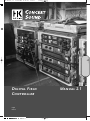 1
1
-
 2
2
-
 3
3
-
 4
4
-
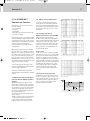 5
5
-
 6
6
-
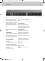 7
7
-
 8
8
-
 9
9
-
 10
10
-
 11
11
-
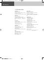 12
12
-
 13
13
-
 14
14
-
 15
15
-
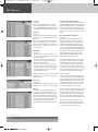 16
16
-
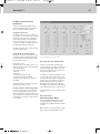 17
17
-
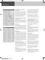 18
18
-
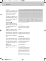 19
19
-
 20
20
-
 21
21
-
 22
22
-
 23
23
-
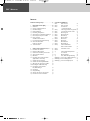 24
24
-
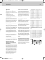 25
25
-
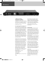 26
26
-
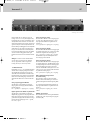 27
27
-
 28
28
-
 29
29
-
 30
30
-
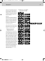 31
31
-
 32
32
-
 33
33
-
 34
34
-
 35
35
-
 36
36
-
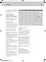 37
37
-
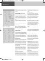 38
38
-
 39
39
-
 40
40
-
 41
41
-
 42
42
-
 43
43
-
 44
44


HK Audio Digital Field Controller (DFC) Manuale utente
- Categoria
- Apparecchiature musicali supplementari
- Tipo
- Manuale utente
