
Quad Monitor Desk Stand
Scan the QR code with your mobile device or follow the link
for helpful videos and specifications related to this product.
Instruction Manual
https://vivo-us.com/products/stand-v104f
SKU: STAND-V104F
Chat live with an agent!
GET IN TOUCH | Monday-Friday from 7:00am-7:00pm CST

2
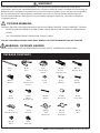
PACKAGE CONTENTS
WARNING!
If you do not understand these directions, or if you have any doubts about the safety of the
installation, please call a qualified technician. Check carefully to make sure there are no missing or
defective parts. Improper installation may cause damage or serious injury. Do not use this product
for any purpose that is not explicitly specified in this manual. Do not exceed weight capacity.
We cannot be liable for damage or injury caused by improper mounting, incorrect assembly or
inappropriate use.
TIPOVER WARNING
SERIOUS OR FATAL CRUSHING INJURIES CAN OCCUR FROM TIPOVER. TO HELP PREVENT TIPOVER:
• NEVER ALLOW CHILDREN TO CLIMB, STAND, HANG, OR PLAY ON ANY PART OF MONITOR OR
STAND.
• USE TIPOVER RESTRAINT OR ANCHOR STAND TO WALL
USE OF TIPOVER RESTRAINTS MAY ONLY REDUCE, BUT NOT ELIMINATE RISK OF TIPOVER.
WARNING: CHOKING HAZARD
SMALL PARTS - NOT FOR CHILDREN UNDER 3 YEARS. ADULT SUPERVISION IS REQUIRED.
a (x1)
Pole
b (x1)
Base
c (x1)
Decorative
Cover
d1 (x1)
Center
Monitor Arm
d3 (x1)
Mount
e (x4)
Monitor Arm
Cover
f (x4)
Pad
NOTE: SOME HARDWARE INCLUDED MAY NOT BE USED
d2 (x2)
Monitor Arm
h (x3)
M6x29
i (x4)
M8x10
j (x16)
M4x12
Thumbscrew
g (x2)
M10x47
k (x16)
M4x30
m (x2)
Spare Cap
l (x16)
M4 Spacer
n (x1)
Allen Wrench Set
o (x1)
Wrench
p1 (x2)
Side
VESA Plate
q1 (x2)
Nut
p2 (x2)
Center
VESA Plate
q2 (x2)
M4x6
r (x4)
Wire Clip

3
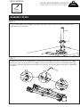
ASSEMBLY STEPS
TOOLS NEEDED
22lbs
(9.98kg)
DO NOT EXCEED WEIGHT CAPACITY.
Failure to do so may result in serious injury.
Phillips
Screwdriver
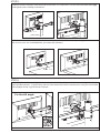
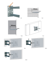
STEP 1
Install the pole (a) to the base (b) using M6x29 bolts (h). Tighten with a Phillips screwdriver and
install decorative cover (c).
PER MONITOR
STEP 2
Assemble the monitor arms (d1, d2) by placing plastic pads (f) on the top and bottom of arms (d2)
and inserting them into the center arm (d1) as shown in the diagram. Secure with M10x47 Bolts (g)
and tighten with the large Allen wrench (n). Press monitor arm covers (e) onto the top and bottom of
arm joints.

4
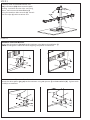
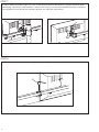
Carefully slide assembled monitor arm
(d1) and mount (d3) down onto the pole,
making sure holes for wire clips are facing
down, and secure with M8x10 bolts (i)
using the medium Allen wrench (n). Attach
the wire clips (r) to the monitor arm.
STEP 4
OPTION A: Flat Back Monitor
Attach the VESA plates (p1, p2) to the monitors using M4x12 thumb bolts (j).
NOTE: Hand tighten screws to avoid stripping the plastic screw heads.
STEP 3
OPTION B: Curved/Recessed Back Monitor
Attach the VESA plates (p1, p2) to the monitors using M4 spacers (l) and M4x30 bolts (k). Tighten with
a Phillips screwdriver.

5
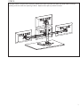
STEP 5
Slide the center monitors onto the heads of monitor arm and mount. Secure with the M4x6 bolts (q2)
and tighten with a Phillips screwdriver.
Pry o the plastic cover and tighten the nut on the side of the tilt joint with the wrench (o) to fix the tilt
angle of side monitors. Tighten the grub screw on the back of center monitor joint using the small Allen
wrench (n) to fix tilt angle of center monitor.
STEP 6
n
grub
screw
Fix the tilt angle
o
è O
ÇNI ÇO
è N
ÇNI Ç
O
Slide the side monitors onto the heads of monitor arm and install the security nuts (q1). Make sure
the security nuts are installed before you rotate the monitors.
q1
d1, d2
d1, d2
q2

6
STEP 7
To adjust center monitor height, turn the screw behind center monitor joint using the medium Allen
wrench (n). To level the side monitors, remove the security nut and turn the bolt with the small Allen
wrench (n) to raise or lower the monitor. Replace nut aer the adjustment.
STEP 8
Pry o the plastic cover and use the large Allen wrench (n) to adjust swivel joints if needed.
n
n

7
STEP 9
Manage cables using the wire clips (r). Remove the split cap from the pole and feed cables through,
pulling ends out from the opening in back. Replace the split cap when finished.

LAST UPDATED: 03/05/2020
Open Monday - Friday 7:00am - 7:00pm CST,
our dedicated support team can oer immediate assistance with rapid response times. If any
parts are received damaged or defective, please contact us. We are happy to replace parts to
ensure you have a fully functioning product.
FOR MORE VIVO PRODUCTS, CHECK OUT OUR WEBSITE AT: www.vivo-us.com
AVG. RESPONSE TIME (within oice hrs): 1HR 8M
- 23% within < 15m
- 38% within < 30m
- 61% within < 1hr
- 83% within < 2hr
- 92% within < 3hr
Love your new VIVO setup and want to share?
Tag us in your photo! @vivo_us
AVG. RESOLUTION TIME (within oice hrs): < 15 M
www.vivo-us.com
Chat live with an agent!
AVG. RESOLUTION TIME (within oice hrs): 5M 4S
309-278-5303
-
 1
1
-
 2
2
-
 3
3
-
 4
4
-
 5
5
-
 6
6
-
 7
7
-
 8
8


in altre lingue
- English: Vivo STAND-V104F
Documenti correlati
Altri documenti
-
 StarTech.com ARMBARDUOV Manuale del proprietario
-
SunriseMedical EIZ9 Manuale del proprietario
-
 VISA VE-L55-T Manuale del proprietario
-
Amazon B010QZCT5W Manuale utente
-
Amazon Basics K001387 Manuale utente
-
Weed Eater HD12538F Manuale utente
-
Star Trac Ion Computer Manuale del proprietario
-
Spirit JOHNNY G SPIRIT BIKE Manuale del proprietario
-
Fellowes LOTUS VE SIT-STAND Manuale del proprietario

